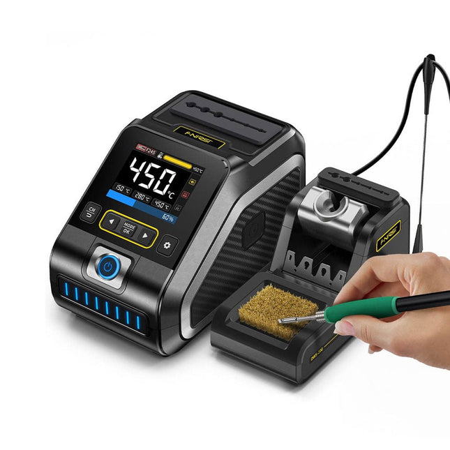
The FNIRSI DWS-200 is a powerful 200 W smart soldering station, ideal for electronic soldering applications. Powered by a switch-mode power supply, it operates smoothly with a wide voltage input range of 100-240 V. The station provides an adjustable temperature range from 100°C to 450°C (212°F to 842°F) and allows for easy switching between °C and °F.
To enhance efficiency, it supports up to three preset temperature values and can connect to a soldering iron stand for standby mode activation. The station also features a dynamic temperature curve mode for real-time data monitoring, ensuring precise and consistent performance in demanding soldering tasks.
Features
Maximum power output of 200 W, allowing for fast heating
Wide adaptive voltage input of 100-240 V
2.8" HD color TFT display with intelligent control
Multiple preset groups to switch between different settings quickly
Supports F245 and F210 soldering handle types, offering flexibility for different soldering applications
Real-time sleep mode to extend the life of the soldering tip
Multi-mode real-time monitoring for power and temperature status, enhancing safety and precision
Specifications
Peak Power
200 W (max)
Temperature Range
100°C~450°C (212°F~842°F)
Display
2.8" TFT HD Color Screen
Heating Time
1 sec
Melting Time
3 sec
Input Voltage
100-240 V (AC)
Input Fuse
3 A
Soldering Handle Type
F245
Dimensions (Station)
156 x 96 x 103 mm
Weight (Station)
475 g
Included
1x FNIRSI DWS-200 Soldering Station
1x Soldering Handle F245
6x Soldering Tips (B, KU, K, C2, I, JS)
1x Connecting Cable
2x Helping Hands
1x Power Cable (EU)
Downloads
Manual
Firmware V1.3
Het boek beschrijft de werking van digitale circuits vanaf schakelingen met poorten tot aan de werking van een processor. Van elke schakeling of systeem kan de werking worden gesimuleerd. Hierbij wordt het gedrag van componenten en het verloop van signalen in de tijd op ingangen, uitgangen en relevante verbindingslijnen zichtbaar gemaakt. Zo wordt in detail gevisualiseerd wat het gedrag is van de hardware als er een instructie wordt uitgevoerd.
Het boek is opgebouwd uit drie modules die de volgende onderwerpen behandelen:
Basismodule
Poorten en combinatorische schakelingen.
Hoe rekent een computer?
Hoe werkt een rekenmachine?
Module Digitale Techniek
Hoe ontwerp je combinatorische schakelingen m.b.v. Boole-algebra?
Sequentiële schakelingen en het ontwerpen van ‘Finite State Systems’.
Complexe schakelingen als decoders, multiplexers, asynchrone en synchrone tellers.
Module Computerarchitectuur
Hoe werkt een ‘loopje’ precies? If-then-else, while en for loops.
De Harvard-architectuur.
Hoe verloopt de communicatie tussen de aanroeper en de aangeroepene bij aanroep van een procedure?
Bij de module Computerarchitectuur worden programma’s in de taal assembler geschreven. Hierbij wordt gebruik gemaakt van een instructieset van slechts 15 instructies.
Website
Het boek wordt ondersteund door de website: www.science.uva.nl/amstel/SIM-PL. De SIM-PL software en de componenten die nodig zijn voor de simulaties kunnen hiervandaan worden gedownload. Ook staan hier antwoorden op vragen en vraagstukken. Verder zijn op deze site collegesheets voor docenten en voorbeelden van tentamens beschikbaar.
Doelgroepen
VAN 0 EN 1 TOT PROCESSOR is geschreven voor iedereen die geïnteresseerd is in de basisprincipes waarop de werking van computers berust. Het boek is zeer geschikt voor studenten Informatica, Technische Informatica en E-technology in het hoger onderwijs en het MBO. Het boek kan worden ingezet bij vakken als Digitale Techniek, Embedded Systems en Architectuur & Computerorganisatie. Delen van de eerste drie hoofdstukken zijn opgenomen in modules voor de vakken Informatica, NLT en Wiskunde D in het voortgezet onderwijs.
Ben Bruidegom is werkzaam bij het AMSTEL-Instituut van de Universiteit van Amsterdam als ontwikkelaar van educatieve hard- en software en docent aan het College of Science van deze universiteit. Hij heeft tientallen jaren ervaring op het gebied van de technische automatisering en het ontwikkelen van onderwijs hiervoor.
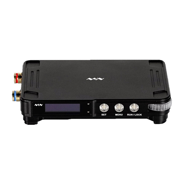
MDP-P906 has a built-in cooling fan, and maximum output power of up to 300 W, which meets a wider range of testing needs and application scenarios. Through 2.4 GHz wireless communication, it can be connected to MDP-M01 Smart Digital Monitor module to realize the free combination of multiple channels of 300 W per channel.
MDP-P906 has the index, stability and reliability comparable to a professional power supply. It can output pure current, and provide powerful functions such as programmable output, timing output, timing control, automatic compensation, boost mode, etc., making itself a real cost-effective, smart and customized programmable linear DC power supply.
MDP-P906 adopts a precision CNC machined aluminum alloy shell, with fine workmanship, novel, mini and beautiful appearance, it completely subverts the rigid image of traditional desktop power supply. With stackable modular design and wireless communication function, MDP-P906 can work independently or paired, both on the workbench, and be carried out for on-site maintenance. MDP-P906 is a perfect solution for electronic engineer, especially field application engineers to meet different needs of power sources.
Built-in silent cooling fan, instant cooling, ensure a stable and efficient output!
Smart linear compensation, constant voltage & constant current
Positive & negative output, series boost, parallel current sharing
Applications
Universal tests and teaching experiments in R&D laboratory
Maintenance of digital products
Property verification and fault diagnosis of devices and circuits
Emergency power supply for model airplanes and vehicles
Power supply testing of RF and microwave circuits or modules
Quality control and quality inspection
Supply purified power for high-accuracy digital-analog hybrid circuits and Hi-Fi audio devices
Specifications
Input
DC 4.2-30 V/14 A (Max)QC 3.0/PD2.0, 20 V/5 A (Max)
Output
0-30 V/0-10 A, 300 W (Max)
Conversion efficiency
95%
Output resolution
10 mV/2 mA, up to 1 mV/1 mA via Display Control module
Output accuracy
0.03%+5 mV0.05%+2 mV
Adjustment rate
Load adjustment rate <±0.01%Power adjustment rate <±0.01%
Ripple and noise
<250 uVrms, 3 mVpp; 2 mArms
Transient response
<4 uS
Safety protections
Input over-voltage, under-voltage, reverse connection protection, output over-current, back-flow protection and over-temperature protection
Others
Automatically shut-down and enter micro-power modeSupport USB firmware upgrade
Dimensions
112 x 66 x 20 mm
Weight
181 g
Included
1x MDP-P906 Digital Power Supply
2x Output Cable
1x User Manual
Downloads
User Manual v1.1
Firmware v1.32
Mit Arduino – Schaltungsprojekte für Profis wird der Leser umfassend in die Hardware und Software der Arduino-Plattform eingeführt. Einfache, leicht verständliche Projekte am Anfang des Buches führen Schritt für Schritt in die Open-Source-Plattform ein. Die Projekte werden dann zunehmend komplexer, um dem Leser möglichst viele konkrete Lösungsmöglichkeiten aufzuzeigen, die mit dem Arduino-Mikrocontroller auch für angehende Profis zur Verfügung stehen.
Dabei wird neben den erforderlichen theoretischen Grundlagen stets größter Wert auf eine praxisorientierte Ausrichtung gelegt. So werden wichtige Techniken wie AD-Wandlung, Timer oder Interrupts stets in Praxisprojekte eingebettet. Es entstehen Lauflichteffekte, ein Aufwachlicht, voll funktionsfähige Voltmeter, präzise Digitalthermometer, Uhren in allen Variationen, Reaktionszeitmesser oder mausgesteuerte Roboterarme. Und ganz nebenbei hat der Leser die Grundlagen der zugehörigen Controller-Technik verstanden und im wahrsten Sinne des Wortes begriffen.
Valve Amplifiers are regarded by many to be the ne plus ultra when it comes to processing audio signals. The combination of classical technology and modern components has resulted in a revival of the valve amplifier. The use of toraidal-core output transformers, developed by the author over the past 15 years, has contributed to this revival. The most remarkable features of these transformers are their extremely wide frequency ranges and their very low levels of linear and nonlinear distortion.
This book explains the whys and wherefores of toroidal output transformers at various technical levels, starting with elementary concepts and culminating in complete mathematical descriptions. In all of this, the interactions of the output valves, transformer and loudspeaker form the central theme.
Next come the practical aspects. The schematic diagram of a valve amplifier often appears to be very simple at first glance, but anyone who has built a modern valve amplifier knows that a lot of critical details are hidden behind this apparent simplicity. These are discussed extensively, in connection with designs for amplifiers with output powers ranging from 10 to 100 watts. Finally, the author gives some attention to a number of special valve amplifiers, and to the theory and practice of negative feedback.
In summary, this book offers innovative solutions for achieving perfect audio quality. Do-it-yourself builders, as well as persons who want to gain a deeper technical understanding of the complex world of audio transformers, valve amplifiers and audio signal processing, will find this book a rich and useful source of information.
This clear acrylic case is the official case for the HackRF One/Pro board. It can replace the standard black plastic case of the HackRF One/Pro.
Assembly Instructions
Use a guitar pick or spudger to extract the HackRF One/Pro circuit board from the black plastic case.
Insert one long screw into each corner of the bottom acrylic panel. Secure each long screw with a short (5 mm) spacer on the opposite side of the panel.
Place the HackRF One/Pro circuit board (facing up) on top of the bottom panel, fitting the ends of the long screws through the corner mounting holes of the circuit board.
Secure the circuit board with one long (6 mm) spacer in each corner.
Place the top acrylic panel on top of the circuit board, aligning the cutouts with the circuit board’s expansion headers.
Secure each corner with a short screw.
Note: Do not overtighten! Hand-tighten only at every step.
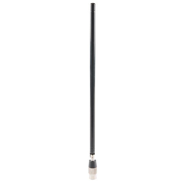
ANT500 from Great Scott Gadgets is a telescopic antenna designed for operation from 75 MHz to 1 GHz. Its total length is configurable from 20 cm to 88 cm. ANT500 is constructed of stainless steel and features an SMA male connector, rotating shaft, and adjustable elbow.
ANT500 is a 50 ohm general purpose antenna. It is the perfect first antenna for use with HackRF One/Pro.
SPD3000X Series Linear Programmable DC Power Supply has a 4.3-inches TFT LCD display, Supports Programmability and Real Time Wave Display, bringing a new experience to users. It has three isolated outputs: two adjustable channels and one selectable channel from 2.5V, 3.3V, and 5V. It also has output short and overload protect function, and can be used in production and development.
Features
3 independent controlled and isolated output, 32V/3.2A×2, 2.5V/3.3V/5V/3.2A×1, total 220W.
5 digits Voltage, 4digits Current Display, Minimum Resolution: 10mV/10mA.
Supports panel timing output functions.
4.3 inch true color TFT LCD 480x272 pixel display.
3 kinds of output modes: independent, series, parallel.
100V/120V/220V/230V compatible design to meet the needs of different power grids.
Intelligent temperature-controlled fan, effectively reducing noise.
Clear graphical interface, with the waveform display function
Internal 5 groups of system parameter save/recall, supports data storage space expansion.
Provides PC software: Easypower, supports SCPI, LabVIEW driver.
High-resolution and high-precision output
The highest resolution of 10mV/10mA, provides excellent setting and read back accuracy. This ensures accurate output even with very with small changes in voltage or current. This is impossible for a low resolution power supply.
Series/parallel/independent mode function
Series and parallel function allows two channels combined into one output with more power output capability, extending the application range. Each of 3 channels power can be turned on or off independently and also can be turned all on or all off.
Panel displays the timing output
Through the panel operation, 5 groups of timing settings and output control can be displayed, which provides users a simple power programming function. Also a connection can be made with Siglent’s EasyPower PC software providing a full range of communication and control requirements.
Save/Recall setting parameters
SPD3000X series programmable power supply can save or recall 5 groups of setting parameter in internal storage, also supports external storage expansion. You can easily obtain the settings you needed.
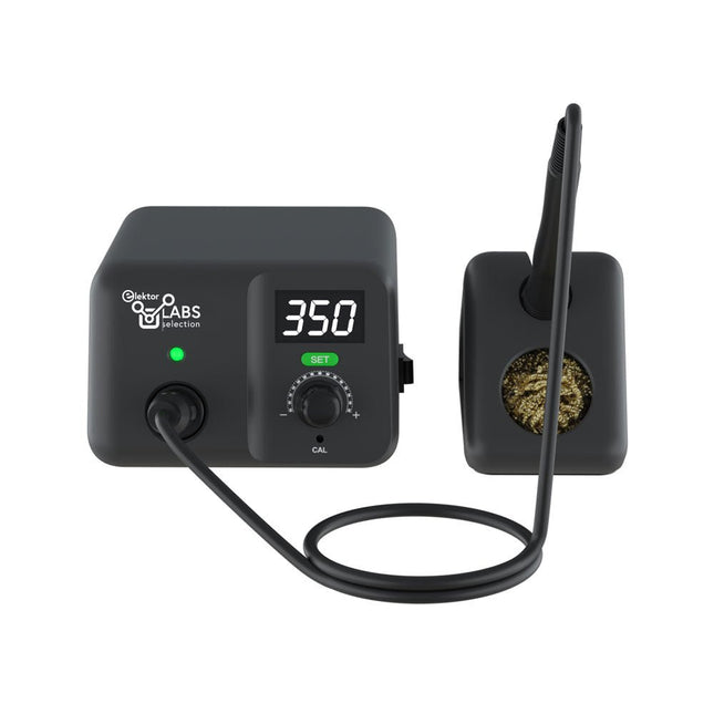
Soldering station for precision soldering with actively heated soldering tip
The AE970D soldering iron station is a 80 W high power tool to heat up to solder fastly. Its wide temperature range of 150-550°C (302-1022°F) could meet all your soldering needs. Thanks to its high performance plug-and-play integrated active tip, AE970D can reach melting point within 9 seconds. Patented close-loop automatic constant temperature control technology can ensure its soldering with high stability, excellent performance and precise accuracy.
Features
80 W high power to enable fast heating up
Wider temperature range of 150-550°C (302-1022°F) to meet all your soldering needs
High performance plug-and-play integrated active tip, can reach melting point within 9 seconds
Patented close-loop automatic constant temperature control technology to ensure high stability, excellent performance and precise accuracy
Specifications
Power
80 W
Input voltage
110 VAC / 230 VAC
Output voltage
25 VAC
Temperature range
150-550°C (302-1022°F)
Heating element
T80 series integrated active heater
Temperature stability
±1°C/±1.8°F (when temperature >200°C/400°F)
Tip to ground resistance
<2 Ω
Tip to ground voltage
<2 mV
Power cord length
1 m
Handle cable length
1.2 m
Dimensions
148 x 120 x 85 mm
Weight (main unit)
1.33 kg
Included
Main unit
Soldering iron incl. soldering tip T80-D12
Iron stand
Brass wool
Manual
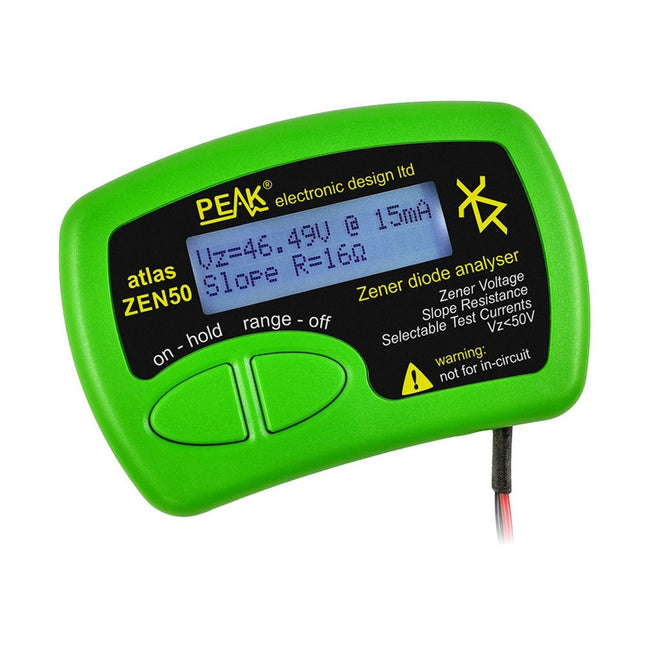
The Peak Atlas ZEN50 is ideal for testing Zener diodes (including avalanche diodes), transient suppressors, LEDs and LED strings. It generates constant current pulses (selectable from 2 mA, 5 mA, 10 mA and 15 mA) at voltages from 0 V to 50 V. So even high voltage Zeners or high voltage LED strings can be tested.
Test currents are supplied in narrow pulses to ensure that the component under test remains at a constant temperature.
The voltage of the part is displayed on the screen together with the test current and also a measure of the component's slope resistance (also known as dynamic impedance).
Specifications
Analyzer type
Zeners, LEDs, TVS etc
Test currents
2 mA, 5 mA, 10 mA, 15 mA
Voltage range
0.00 to 50.00 V
Slope resistance range
0 to 8000 Ohms
Battery type
Single AAA (supplied). Life typically 1400 ops
Test method
Triple pulse burst @ 10pps (typ)
Test current duty cycle
3%
Display type
Alphanumeric LCD (with backlight)
Included
Peak Atlas ZEN50 Zener Diode Analyzer
Fitted flexible test leads with gold plated crocs
Comprehensive illustrated user guide
AAA Alkaline battery
Downloads
Datasheet (EN)
User Guide (EN)
User Guide (FR)
User Guide (DE)
User Guide (IT)
The OWON SDS1102 is an affordable benchtop digital oscilloscope that combines solid performance with essential measurement features. This 2-channel oscilloscope offers a 100 MHz bandwidth, a 1 GS/s sampling rate, a 7-inch LCD display, and a 10 kpts memory depth, making it a practical choice for everyday electronics testing, troubleshooting, and education.
The SDS1102 features a simplified trigger system with level and edge triggering, making it easy to capture and analyze common signals. It is designed for applications that do not require deep memory or advanced trigger functions, offering a straightforward and cost-effective solution for basic signal analysis.
Features
Bandwidth: 100 MHz
2 channels
Sample rate: 1 GS/s
Ultra-thin body
7-inch high-res LCD
SCPI and LabVIEW supported
Specifications
Bandwidth
100 MHz
Horizontal Scale (s/div)
5 ns/div – 1000 s/div
Channel
2
Vertical Sensitivity
5 mV/div – 5 V/div (at input)
DC Gain Accuracy
3%
Vertical Resolution (A/D)
8 bits (2 channels simultaneously)
Input
Input Impedance
1 MΩ, 10 pF
Input Coupling
AC, DC, GND
Max Input Voltage
±400 V, CATI, CATII
Passive probes
х1; х10
Probe Attenuation Factor
х1; х10; х100; х1000
Trigger System
Trigger Mode
Auto, Normal, Single
Trigger Type
Edge, Video
Edge Trigger Source
CH1, CH2
Video Trigger
Sampling Type
Real-time
Sample Rate
1 GS/s
Equivalent Sample Rate
No
Wavelength
10K pts
Interpolation
sin(x)/x
Measurement and Mathematical Treatment System
Automatic Measurement
Vpp, Vavg, RMS, Frequency, Period, Vmax, Vmin, Vtop, Vbase, Width, Overshoot, Pre-shootRise time, Fall time, +Width, -Width, +Duty, -Duty, Delay A→B, Delay A→B, area, cycle area
Math Functions
Addition, Subtraction, Multiplication, Division, FFT
General Characteristics
Display type
7" color LCD
Display Resolution
800 x 480
Power
100-240 V, 45-440 Hz, <15 W
Dimensions
301 x 70 x 152 mm
Weight
1.1 kg
Included
1x OWON SDS1102 Oscilloscope
2x Oscilloscope probes
1x Probe adjust
1x Mains power cord
1x USB cable
1x CD-Rom
1x Quick guide
Downloads
Quick Guide
Manual
PC Software
SCPI Commands
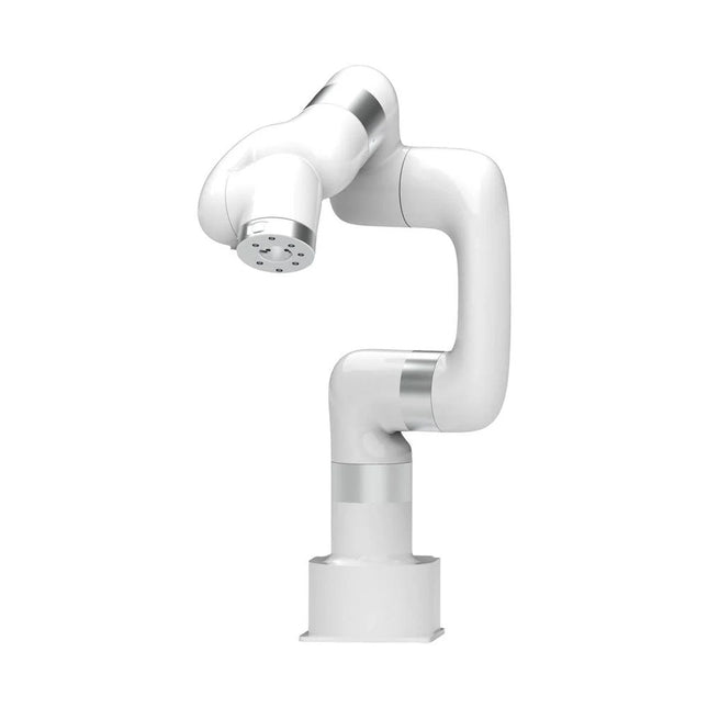
This multi-axis robot perfectly balances power and size.
Features
Payload: 5 kg
Reach: 700 mm
Repeatability: 0.1 mm
Max Speed 1000 mm/s
Applications
Machine Tending
Bin Picking
Mobile platform
Lab Automation
Robotic Research
Durable Collaborative robots for your automation
Industrial-grade harmonic drive and servomotors guarantee 24/7 working without stop.
Crafted from Carbon fiber, 15 kg weight makes it possible for easier deployment.
Flexible deployment with safe feature
Hand teaching, lightweight, space-saving and easy to re-deploy to multiple applications without changing your production layout. Perfectly for recurrent tasks.
Collision detection is available for all of our cobots. Your safety is always the top priority.
Graphical interface for beginner-friendly programming
Compatible with various of operation systems, including macOS and Windows.
Web-based technology compatible with all major browsers.
Drag and drop to create your code in minutes.
Powerful and open source SDK at your fingertips
Fully functional open-source Python/C++ SDK provides more flexible programming.
ROS/ROS2 packages are ready-to-go.
Example codes help you to deploy the robotic arm smoothly.
Specifications
UFactory 850
xArm 5
xArm 6
xArm 7
Payload
5 kg
3 kg
5 kg
3.5 kg
Reach
850 mm
700 mm
700 mm
700 mm
Degrees of freedom
6
5
6
7
Repeatability
±0.02 mm
±0.1 mm
±0.1 mm
±0.1 mm
Maximum Speed
1 m/s
1 m/s
1 m/s
1 m/s
Weight (robot arm only)
20 kg
11.2 kg
12.2 kg
13.7 kg
Maximum Speed
180°/s
180°/s
180°/s
180°/s
Joint 1
±360°
±360°
±360°
±360°
Joint 2
-132°~132°
-118°~120°
-118°~120°
-118°~120°
Joint 3
-242°~3.5°
-225°~11°
-225°~11°
±360°
Joint 4
±360°
-97°~180°
±360°
-11°~225°
Joint 5
-124°~124°
±360°
-97°~180°
±360°
Joint 6
±360°
±360°
-97°~180°
Joint 7
±360°
Hardware
xArm
Robot specs
Ambient Temperature Range
0-50°C
Power Consumption
Min 8.4 W, Typical 200 W, max 400 W
Input Power Supply
24 V DC, 16.5 A
Footprint
Ø 126 mm
Materials
Aluminum, Carbon Fiber
Base Connector Type
M5x5
ISO Class Cleanroom
5
Robot Mounting
Any
End Effector Communication Protocol
Modbus RTU(rs485)
End Effector I/O
2x DI/2x DO/2x AI/1x RS485
Communication Mode
Ethernet
Included
1x xArm 6 robotic arm
1x AC control box
1x Robotic arm power cable
1x Robotic arm end effector adapter cable
1x Robotic arm signal cable
1x Control box power cable
1x Network cable
1x Mounting tool
1x Quick start guide