
Search results for "elektor or special or introduction or to or electronics or with or arduino"
-
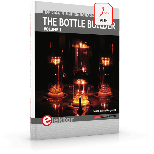
Elektor Digital The Bottle Builder (E-book)
The author, Johan Basse Bergqvist, is an engineer, a musician, and an audiophile with a knack for building projects that produce the desired results. The combination of these skills leads to a uniquely valuable perspective on audio design that is routinely reflected in the book and passed on to the readers. Several design projects are provided, 40 in total. The designs are explained, and the unique features or methods he uses are described in further detail. Each design includes detailed schematics and a complete parts list. Many of the projects also include layout documentation in the form of CAD photos of the PCB layouts. The range of projects is very diverse and includes something that will appeal to everyone. Stereo amplifiers, guitar and bass amplifiers, preamplifiers for phono, and microphones are all covered. Several variants for each type are included, and the power amplifier designs range from a few watts to several hundred watts, which meet almost any power level you might tackle.
€ 64,95
Members: € 58,46
-

Elektor Digital Hochfrequenz-Baubuch (PDF)
Die Hochfrequenztechnik ist eines der Gebiete, auf denen man auch heute noch eigene Ideen in die Tat umsetzen kann. Unzählige Schaltungsvarianten mit besonderen Zielsetzungen geben Raum für sinnvolle Experimente und Projekte. Vieles kann man nicht einfach kaufen. Detektorradios ohne eigene Energiequelle, einfache Röhrenempfänger mit einem Hauch von Nostalgie, die ersten Empfangsversuche mit dem Software Defined Radio oder Spezialempfänger für den Amateurfunk, all dies lässt sich mit wenig Aufwand realisieren. Lange Zeit war das Radiobasteln der Einstieg in die Elektronik. Inzwischen gibt es auch andere Wege, vor allem über Computer, Mikrocontroller und die Digitaltechnik. Allerdings kommen die analogen Wurzeln der Elektronik oft zu kurz. Die Radiotechnik eignet sich besonders gut als Lernfeld der Elektronik, weil man hier mit den einfachsten Grundlagen beginnen kann. Aber auch die Verbindung zur modernen Digitaltechnik liegt auf der Hand, wenn es z. B. um moderne Abstimmverfahren wie PLL und DDS oder um moderne DSP-Radios geht. Dieses Buch gibt einen Überblick und stellt eine Sammlung einfacher Projekte vor. Der Autor möchte Sie dabei unterstützen, eigene Ideen zu entwickeln, eigene Empfänger zu entwerfen und sie zu erproben.
€ 32,80
Members: € 29,52
-
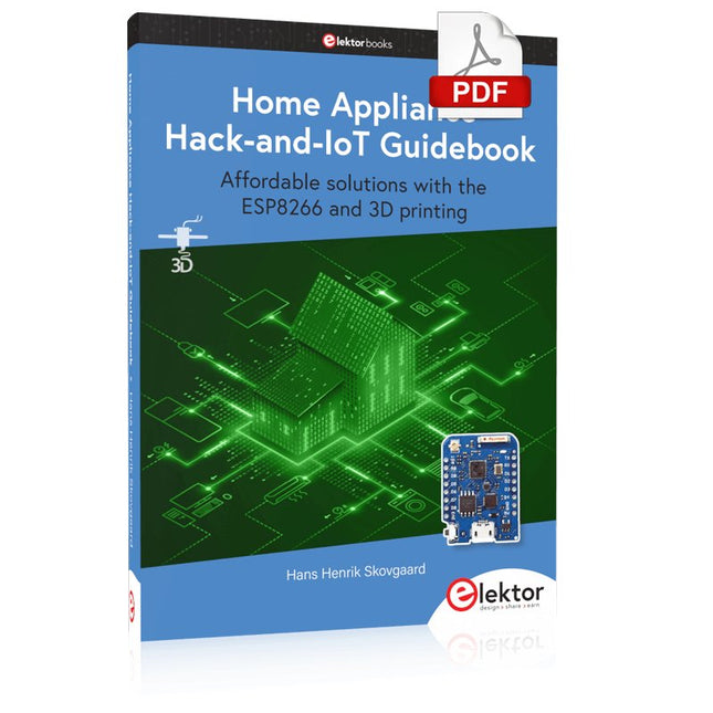
Elektor Digital Home Appliance Hack-and-IoT Guidebook (E-book)
Affordable solutions with the ESP8266 and 3D printing If you are looking for a small yet powerful IoT device, you are likely to come across the ESP8266 and compatible products on the market today. One of these, the Wemos/Lolin D1 Mini Pro board strikes a remarkable balance between cost and performance. A small and very affordable prototype board, the D1 Mini Pro stands out with its WiFi functionality and a 16-Mbytes flash memory for easy creation of a flash file system. In addition, there are sufficient input and output pins (only one analog input though) to support PWM, I²C, and One-Wire systems to mention but a few. The book describes the operation, modding, construction, and programming of home appliances including a colorful smart home accessory, a refrigerator/greenhouse controller, an AC powerline monitor, a door lock monitor, and an IKEA Trådfri controller. As a benefit, all firmware developed for these DIY, "IoT-ized" devices can be updated over-the-air (OTA). For most of the designs in the book, a small printed circuit board (PCB) and an enclosure are presented so readers can have a finished and attractive-looking product. Readers having – or with access to! – a 3D printer can "print" the suggested enclosures at home or in a shop. Some of the constructions benefit from a Raspberry Pi configured as a gateway or cms server. This is also described in detail with all the necessary configuring. You don’t need to be an expert but the prerequisites to successful replication of the projects include basic skills with PC software including the ability to surf the Internet. In terms of hardware, you should be comfortable with soldering and generally assembling the PCBs presented in the book. All custom software written for the IoT devices, the PCB layouts, and 3D print files described in the book are available for free downloading.
€ 34,95
Members: € 31,46
-
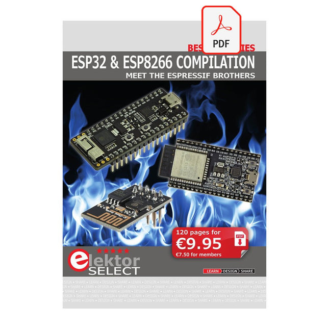
Elektor Digital ESP32 & ESP8266 Compilation (EN) | E-book
The ESP8266 from Espressif is a Wi-Fi microchip with full TCP/IP stack and microcontroller capability. It has made waves in the maker community with its low price. But many developers were unhappy with ESP8266's high power consumption. The ESP32, equipped with a ULP (Ultra Low Power) coprocessor, offers a remedy for this. This e-book features a number of projects featuring ESP32 & ESP8266 as well as an interview with the CEO of Espressif Teo Swee Ann. Articles ESP32 for Use in Industry 4.0 Equipment Scrolling Message Display, 512 LEDs controlled over Wi-Fi via an ESP-12F The Connected Greenhouse IoT demonstration project using MQTT and Node-RED VFD-tube Clock with ESP32 with an accurate Internet-derived time ESP32 Low Power DCF77 Emulator with ESP8266 ESP8266 on the Elektor Android I/O Board The Reason Behind the Hugely Popular ESP8266? Wi-Fi Desktop Thermostat Timers for the Wi-Fi Desktop Thermostat PlatformIO, the Universal Programming Tool Weather Display, Visualize current weather data on an LC display GoNotify, a Flexible IoT Sensor Interface ESP32 for Power Users USB Programming Adaptor for ESP8266 Getting started with ESP32 and the Arduino IDE MicroPython, Python for small systems RGBDigit Clock WLAN for Microcontrollers Return of the Wi-Fi Controller Board Compact and Self-contained WLAN
€ 9,95
Members: € 8,96
-

Elektor Digital Mikrocontroller-Module (PDF)
Grundlagen und Selbstbau Weshalb nicht damit beginnen, Mikrocontroller-Module selbst zu entwickeln, zumindest aber sich in Gedanken mit solchen Aufgaben zu beschäftigen? Wie Mikrocontroller-Module aufgebaut sind und wozu sie verwendet werden, soll in 'Mikrocontroller-Module – Grundlagen und Selbstbau' dargestellt werden. Das vorliegende Buch beleuchtet Mikrocontroller-Module, die vor allem zum Experimentieren, zum Lernen und zum Einarbeiten in die Entwicklung und Programmierung von Embedded Systems gedacht sind. Die Entwurfsgrundsätze, Lösungsvorschläge und Projekte, die in diesem Buch beschrieben werden, sind aus zwei Ideen hervorgegangen: Erstens können neue Entwicklungen zwischen den weit verbreiteten kostengünstigen Mikrocontroller-Modulen und der industriellen Computer- und Steuerungstechnik ihren Platz finden und zweitens ist es eine Herausforderung an sich, solche Module zu entwickeln und einzusetzen. In den ersten sieben Kapiteln dieses Buches werden die technischen Grundlagen diskutiert und anhand eigener Entwicklungen veranschaulicht. Das achte Kapitel gibt einen Überblick über diesen Modulbaukasten. Alle Fotos aus dem Buch können hier vierfarbig heruntergeladen werden.
€ 32,80
Members: € 29,52
-

Elektor Digital I/O-Projekte für den PC (E-book)
I/O-Projekte für den PC (E-book)
€ 34,80
Members: € 31,32
-

Elektor Digital Audioschaltungstechnik (PDF)
Audioschaltungstechnik (E-book)
€ 29,80
Members: € 26,82
-

Elektor Labs Elektor Low-Noise Lab Power Supply
The Elektor Low-Noise Lab Power Supply is a fully analogue, adjustable, medium-power symmetrical bench supply that contains no switching or digital components. It provides an output voltage adjustable between 0 V and ±22 V, and an output current adjustable from 0 A to 1 A. Because it avoids any form of switching circuitry, the design delivers extremely low noise. To display both output voltages and currents, four miniature moving-coil panel meters are used. Most modern laboratory power supplies and AC adapters employ switch-mode techniques. Even the best examples inevitably exhibit high-frequency ripple and other switching artefacts on their output, which can interfere with the testing of sensitive analogue circuits and disturb low-level measurements. To overcome this, the concept here is a completely analogue power supply. Although less efficient than its switch-mode counterparts, the reduced efficiency is of little importance for test-bench use and ensures cleaner, more reliable measurement results. Because many analogue circuits require a symmetrical supply, this design delivers positive and negative output voltages of equal magnitude. A small amount of adjustment is available to compensate for any imbalance. Naturally, a variable current-limit function is also included. The kit includes the components required to build the power supply, except for the transformers. Specifications Output Voltage 0…+22 V, 0, −22 V Output Current 0…+1 A, 0…−1 A Noise −85 dBV, (at 0.95 A/20 V, B = 22 kHz) −84 dBV (at 0.95 A/20 V, B > 500 kHz) Ripple 50 µVRMS (at 950 mA/20 V, B = 22 kHz, mainly 100 Hz component) Included 3x PCBs: Regulator (PCB-1), Mains Filter (PCB-2) and Transformer (PCB-3) All the components except the AC transformers 4x moving-coil meters Additional parts for wiring (wires, banana sockets, IEC Power entry module, etc.) Not included The three AC transformers An enclosure Parts List For the Regulator PCB (240386-1) Resistors (250 mW, 1%) R1 = 12 Ω R2, R8, R37, R62 = 1 MΩ R3, R7, R10, R13, R17, R20, R22, R30, R35, R42, R45, R47, R55, R60 = 100 Ω, 600 mW R4, R5 = 4.7 kΩ R6 = 100 kΩ R9, R12, R14, R36, R38, R39, R61, R63, R66, R72, R78, R79 = 10.0 kΩ, 600 mW R11 = 9.76 kΩ, 600 mW R15, R40 = 44.2 kΩ, 600 mW R16, R41, R77 = 1 kΩ R18, R43 = 1.5 kΩ, 1 W, 5% R19, R44 = 470 Ω, 1 W, 5% R21, R46 = 330 Ω, 600 mW R23, R24, R48, R49 = 1.0 Ω, 1 W R25, R50 = 1 kΩ, 1 W, 5% R26, R28, R51, R53 = 1.000 kΩ 0.1%, 15 ppm/C R27, R29, R52, R54 = 10.00 kΩ 0.1%, 15 ppm/C R31, R56 = 1.2 kΩ, 1 W, 5% R32, R57 = 47 kΩ R33, R58 = 270 Ω R34, R59 = 27 kΩ R64, R69 = 12.0 kΩ R65 = 3.0 kΩ, 600 mW R67, R80 = 470 Ω, 600 mW R68, R70 = 6.8 kΩ, 600 mW R71 = 30.0 kΩ,, 600 mW R73, R74, R75, R76 = 10 MΩ P1, P2, P3 = 10 kΩ, 200 mW, 20%, potentiometer, 1 turns, single, lin., panel mount P4, P5 = 500 Ω, 500 mW, 10%, trimmer, 25 turns, 3296Y-1-501LF Bourns P6, P7 = 10 kΩ, 500 mW, 10%, trimmer, 25 turns, 3296Y-1-501LF Bourns Capacitors C1 = 100 nF, 50 V, 10%, ceramic X7R, LS 5 mm C2, C3, C6, C7, C30 = 10 µF, 63V, 20%, LS 2.5 mm, 3000hours@105°C C4, C5, C8, C9, C13, C14, C18, C19, C23, C24, C28, C29, C31, C32, C38, C39 = 100 nF, 250 V, 10%, PET, LS 7.5 mm C10, C20 = 47 nF, 100 V, 5%, PET, LS 5 mm C11, C21 = 10 nF, 100 V, 5%, PET, LS 5 mm C12, C22 = 220 µF, 35 V, 20%, 0.024 Ω, LS2.5/3.5 mm, Ir 3.4 A, 2000hours@125°C, polymer C15, C25 = 120 µF, 50 V, 20%, ESR 0.02 Ω, Diam. 10 mm max., LS 5 mm C16, C26 = 15 nF, 100 V, 5%, PET, LS 5 mm C17, C27 = 47 nF, 100 V, 5%, PET, LS 5 mm C33, C34 = 22 µF, 50 V, 20%, LS 2 mm, 10000 hours @ 105°C C35, C36, C44, C45 = 1 µF, 100 V, 10%, LS 5 mm, ceramic X7R C37 = 100 uF, 50 V, 20%. LS 3.5 mm C40, C41, C42, C43, C46, C47, C48, C49 = 1000 µF, 50 V, 20%, LS 5/7.5 mm, Ir 3.32 A, 10000hours@105°C, D 16 mm C50, C51, C52, C53 = 47 nF, 100 V, 10%, ceramic X7R, LS 5 mm Inductors L1, L2 = 4.7 µH, 3.2 A, 0.033 Ω, LS 5 mm, RLB0914-4R7ML Bourns L3 = Commom mode choke, 14.5 mH, 3 A, SSRH24NH-30145 Kemet Semiconductors D1, D2, D3, D4, D5, D9, D10, D11, D15 = BAT85, DO-34 D6, D7, D12, D13 = SR560, DO-201AD D8, D14, D16 = 1N4148, DO-35 D17 = Zenerdiode, 5.6 V, 0.5 W, DO-41 D18, D19 = 1N4004, DO-41 D20, D21 D22, D23 = V30100CI-M3/P, dual common cathode, TO-220 D24 = Zener diode, 30 V, 1 W, DO-41 LED1, LED2 = LED, red, T-1 (3 mm) LED3, LED4 = LED, green, T-1 (3 mm) TVS1, TVS2 = BZW50-33B, R6 T1, T2, T4 = BC337.25, TO-92 T3 = NJW0302G, TO-3P T5, T6, T8 = BC327.25, TO-92 T7 = NJW0281G, TO-3P T9 = BD139, TO-126 (SOT-32) IC1 = LM334Z, TO-92 IC2 = LM4040AIZ-5.0/NOPB, TO-92 (TO-226AA-3) IC3, IC4 = OPA2992IDR, SOIC-8 IC5, IC6 = OPA4992IDR, SOIC-14 IC7 = OPA992IDBVR, SOT-23-5 IC8 = LM339N, DIP-14 IC9 = LM317, TO-220 IC10 = LM337, TO-220 Others F1, F2 = 5×20 mm fuse, 1.6 A, fast acting HS1, HS2 = Heatsink MC33271 (for T3/T7), 2.7°C/W, PCB mount, height 63.5 mm K1, K4 = 3-way screw terminal block, LS 3.5 mm, max. 1.5 mm² K2, K3 = 3-way screw terminal block, LS 3.5 mm, max. 1 mm² M1, M3 = Moving coil meter, Range 30 V, type 91C4, 45×45 mm M2, M4 = Moving coil meter, Range 1 A, type 91C4, 45×45 mm² RE1 = Relay DPDT,5V, UA2-5NU Miscellaneous 3× 3-way screw terminal block, LS 3.5 mm, max. 1 mm² (for P1, P2, P3) 4× Pin header, 1×2, vertical, pitch 2.54 mm (for LED1, LED2, LED3, LED4) 4× Pin socket, 1×2, vertical. pitch 2.54 mm (for LED1, LED2, LED3, LED4) 2× Heatsink FK222SA220, 20°C/W, PCB mount (for IC9 & IC10) 2× Mica thermal pad for TO-220, 12×18×0.05 mm (for IC9 & IC10) 2× Insulating bushing IB 6, TO-220 (for IC9 & IC10) 2× Ceramic thermal pad, 23×20×2 mm (for T3 & T7) 2× PCB Fuse Holder, for 5×20 mm fuse, 10 A (for F1, F2) 2× Cover for PCB Fuse Holder, transparent (for F1, F2) 2× 2-way screw terminal block, LS 3.5 mm, max. 1 mm² (for M1 & M3) 2× 2-way screw terminal block, LS 3.5 mm, max. 1.5 mm² (for M2 & M4) 8× M3 solder lug, thickness 0.35 mm (for M1…M4) M4 solder lug, thickness 0.35 mm (to connect 4 mm banana connectors) Screened cable, 1 pair, 2×24 AWG/0.22 mm², 1 m (for P1, P2 & P3) IC socket, DIP, 14 contacts (for IC8) M3 washer, plain, steel M3 screw, 16 mm, steel, pan head M3 nut M3 spring washer 50 mm M3 standoff, steel, male-female 12 mm M3 standoff, steel, male-female 10 mm M3 standoff, steel, male-female M3 screw, 8 mm, steel, pan head For the Mains Fiter PCB (240386-2) Resistor R1 = 220 kΩ, 1 W, 500 V, 5% Capacitors C1, C2 = 470 nF, 305 VAC, Class X2, 11 × 27 mm max., LS 15/22.5 mm C3, C4, C5, C6 = 2.2 nF, 300 VAC, Class Y2, 13 × 4 mm, LS 10 mm, PP Inductors L1, L2 = Common-mode choke, 6.8 mH, 1.7 A, TDK B82732R2172B030 Semiconductor MOV1 = TVS varistor, 300 VAC, S14K300 (230 VAC, B72214S0301K101) and SK14K150 (150 VAC, B72214S0151K101) Others K1, K2 = 3-way screw terminal block, LS 7.62 mm F1 = Time-delay fuse, 0.5 A (230 VAC) or 1 A (115 VAC) Miscellaneous 1× Fuse holder, 5×20 mm, 10 A, 500 VAC 1× Transparent fuse cover 4× 10 mm M3 standoff, steel, male–female 4× M3 screw, 8 mm, steel, pan head 4× M3 nut For the Transformer PCB (240386-3) Resistors R1, R2 = 2.7 kΩ, 600 mW, 1% R3 = 10.0 kΩ, 600 mW, 1% Capacitor C1 = 220 µF, 50 V, 20%, Ø10 mm, LS 5 mm, 4000 h @ 105°C Transformers (not included in this kit!) TR1, TR2, TR3 = 2×7 V, 25 VA, PCB-mounted toroid, 70060K Talema Semiconductors D1–D4 = 1N4148, DO-35 D5, D6 = 1N4004, DO-41 D7 = Zener 5.6 V, 1.3 W, DO-41 LED1 = LED, red, T-1 (3 mm) IC1, IC2 = MOC8021M, CTR ≥ 1000%, DIP-6 Others F1, F2, F3 = 160 mA time-delay fuse (230 VAC) or 315 mA time-delay fuse (115 VAC) K1 = 2-way screw terminal block, LS 7.62 mm K2 = 3-way screw terminal block, LS 3.5 mm, max 1.5 mm² K3, K4 = 3-way screw terminal block, LS 3.5 mm, max 1 mm² RE1, RE2 = Relay DPDT, 5 A/250 VAC / 24 VDC Miscellaneaous 1× Pin header 1×2, pitch 2.54 mm + matching socket for LED1 3× Fuse holder 5 × 20 mm, 10 A, 500 VAC + transparent cover 3× M4 screw, 8 mm, pan head + washer for TR1-TR3 8× M3 screw, 8 mm, pan head + nut + washer 8× 10 mm M3 standoff, steel, male–female 2× IC socket, DIP-6 for IC1 & IC2 Additional Parts 1 m red insulated wire, stranded, 1.5 mm² 0.5 m blue insulated wire, stranded, 1.5 mm² 0.5 m black insulated wire, stranded, 1.5 mm², 0.5 m 2 m red insulated wire, stranded, D 0.56 mm (0.25 mm²) 2 m black insulated wire, stranded, D 0.56 mm (0.25 mm²) 0.5 m Multicore Cable, Flexible, 3 Core, 0.75 mm² (24 x 0.2 mm) Red banana socket Black banana socket Blue banana socket Green banana socket IEC Power Entry Module with switch, IEC C14 3 crimp terminals, FASTON, 4.75 x 0.81 mm 3 knobs Links Elektor Labs JumpStarter Page Article (Part 1) Article (Part 2)
€ 299,00€ 249,00Best Price
-
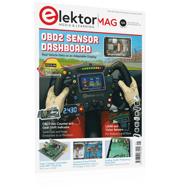
Elektor July/August 2025 (EN)
Elektor GREEN and GOLD members can download their digital edition here. Not a member yet? Click here. OBD2 Sensor DashboardOld Dials Sparked a Quest for Real Data OBD2: Add a Rev Counter and Gear Shift Indicator to Your CarRetro, but Super Useful LiDAR and Vision Sensors for Robotics Sensor+Test 2025 and PCIM 2025 Contact-Free E-Field Measurements (1)A Vibrating Membrane for Assessing DC Voltages or Static Electric Fields Wireless Mailbox NotifierFrom Optical Sensors to Radar, Exploring a Few Options Elektor Mini-WheelieA Self-Balancing Robot Solar CellsPeculiar Parts, the Series Getting Started With a Modern Radar SensorIs an Accurate Measurement on Your Radar? From Life’s ExperiencePaper Factory CybersecurityTough Times for Hackers Siglent Presents Next-Gen Multi-Channel OscilloscopesHigh-Performance Solutions for Modern Power and Embedded Systems Bluetooth 6.0 Brings Enhanced Distance-Ranging ApplicationsNew Version Offers Improved Device Positioning and Location Services Exploring Wireless Communication with BeagleY-AI Err-lectronicsCorrections, Updates, and Readers’ Letters Starting Out in Electronics……Concludes the Topic on Opamps A Powerful AI Code AssistantSpeed Up Your Development with Continue and Visual Studio Code Solar Charge Controller with MPPT (2)The Circuit Ultrasonic Obstacle DetectorA Simple Project to Help Those with Impaired Vision 2025: An AI OdysseyMid-Year Review Raspberry Pi Standalone MIDI Synthesizer (3)Making It Smarter and Adding a User Interface Meshtastic: A Demo ProjectAn Intelligent Mesh of LoRa Radios Analog Audio Frequency GeneratorHigh-Quality Adjustable Frequency Sine Wave Generator
€ 10,95
-

Elektor Digital Elektor Janvier/Février 2020 (PDF)
Elektor Janvier/Février 2020 PDF FR
€ 10,95
-

Elektor Digital Elektronik & Modellbahn 2 (PDF)
Elektronik & Modellbahn 2 (PDF)
€ 24,90
Members: € 22,41
-

Elektor Digital Elektor 03-04/2021 als PDF (DE)
Elektor 03-04/2021 als PDF (DE)
€ 11,90


