
Search results for "siglent OR sdg1032x OR 2 OR ch OR signal OR generator OR 30 OR mhz"
-

Elektor Digital Elektor Mei/Juni 2021 (PDF)
ZELFBOUW LIPO-SUPERCHARGER KITvan prototype tot productie ELEKTOR @ 60gedachten bij zestig jaar elektronica SIGLENT SDM3045X TAFELMULTIMETER DC-STROOMKLEMHall-sensor + ferrietkern + Arduino SOLDEERSTATION 2021makkelijk om te bouwen! KENNISMAKING MET DE PARALLAX PROPELLER 2 (DEEL 2)de ontwikkelomgeving en de code WIFI VOOR DE LORA SWITCHgeïntegreerd in Home Assistant met ESPHome GEEN ANGST VOOR DE CELLULAIRE MODULE! HOUD DE TIJD BIJ MET ESP32 EN TOGGLwerken met de M5Stack KENNISMAKING MET HET RASPBERRY PI PICO-BOARD EN DE RP2040 MICROPYTHON VOOR MICROCONTROLLERStechnieken voor kleine displays 12–200 V DC/DC-CONVERTERvoor buizenversterkers WARMTEZOEKERde Seek Shot Pro warmtebeeldcamera OBJECTGEORIËNTEERD PROGRAMMERENeen korte inleiding met C++ OOST WEST LAB BEST...waar Kurt Diedrich synthesizers bouwt JAVA OP DE RASPBERRY PIdeel 1: GPIO’s DIP-SCHAKELAARSvreemde onderdelen INTERACTIEFcorrecties & updates || brieven van lezers WIENS PRODUCT IS HET EIGENLIJK?recht-op-reparatie beweging laat van zich horen UIT HET LEVEN GEGREPENhet grote blunderboek MICRO-PROFESSORassembleertaal leren op een Z80 ALLE BEGIN......hoeft niet zo moeilijk te zijn – zelfs als het om condensatoren gaat HEXADOKUThe Original Elektorized Sudoku
€ 9,95
-

Seeed Studio Seeed Studio RF Explorer WSUB1G+ Slim Spectrum Analyzer
The Seeed Studio RF Explorer WSUB1G+ is a powerful, high-performance digital spectrum analyzer covering frequencies from 50 kHz to 1 GHz. The Slim model features a robust design, a more conveniently positioned USB connector on the side, and a larger internal battery capacity. Features Internal LNA amplifier and selectable attenuator Low frequency support from 50 KHz covering LF, MF, HF, VHF and UHF up to 960 Mhz New HELP and SET buttons to improve user interface and configuration selection with 2-clicks Wide band coverage to all popular sub-1 Ghz bands, including FM, TV and DTV, ISM, RFID, GSM, etc. Ideal choice for HAM bands from 160 m to 33 cm Pocket size and light weight Solid metal case Spectrum Analyzer mode with Peak Max and Hold, Normal, Overwrite and Averaging modes High capacity internal Lithium battery for 20hs+ of continuous run, rechargeable by USB Multi-platform Windows/Linux/MacOS Open Source software and API libraries Can be extended with internal Expansion Modules for additional band and functionality Specifications Frequency band: 0.05 MHz – 960 MHz Frequency span: 0.1 MHz – 960 MHz Internal selectable LNA 25 dB gain Internal selectable Attenuator 30 dB Graphics LCD 128 x 64 pixels, great visibility outdoors Support included for Windows, Linux and MacOS X Backlight for great visibility indoor Internal Lithium Ion 1800 mA/h rechargeable battery Standard SMA 50 Ω connector Wideband 144/433 MHz dual band telescopic antenna included UHF 400-900 MHz rubber duck articulated antenna included Amplitude resolution: 0.5 dBm Dynamic range: -125 dBm to 10 dBm Absolute Max input power: +30 dBm Average noise level (typical LNA): -125 dBm Frequency stability and accuracy (typical): ±10 ppm Amplitude stability and accuracy (typical): ±2 dBm Frequency resolution: 1 kHz Resolution bandwidth (RBW): Automatic 2.6 kHz to 600 kHz Included 1x Seeed Studio RF Explorer WSUB1G+ Slim Spectrum Analyzer 1x Mini USB cable 1x Dual band 144/430 MHz Telescopic antenna 1x UHF 400-900 Mhz antenna 1x EVA case
€ 204,49
-
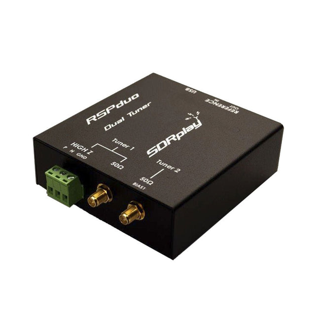
SDRplay SDRplay RSPduo Dual-Tuner 14-bit SDR Receiver (1 kHz to 2 GHz)
The SDRplay RSPduo is a high performance dual-tuner 14-bit SDR receiver. Housed in a high quality steel enclosure, each tuner can operate individually anywhere between 1 kHz and 2 GHz with up to 10 MHz of bandwidth or both tuners can operate simultaneously anywhere between 1 kHz and 2 GHz with up to 2 MHz of bandwidth per tuner. A high stability reference along with external clocking features makes this device ideally suited to industrial, scientific & educational applications. Features Dual tuner provides independent coverage from 1 kHz to 2 GHz using 2 antenna ports simultaneously 14-bit ADC silicon technology Up to 10 MHz visible bandwidth (single tuner mode) or 2 slices of 2 MHz spectrum (dual tuner mode) 3 software-selectable antenna ports (2x 50Ω and 1x 1kΩ high impedance balanced/unbalanced input) High impedance antenna port (1 kHz to 30 MHz) with selectable MW notch filter and choice of 2 pre-selection filters Software selectable AM/FM and DAB broadcast band notch filters for the 2 SMA antenna (1 kHz to 2 GHz) antenna ports External clock input and output enables easy synchronisation to multiple RSPs or external reference clock Powers over the USB cable with a simple type B socket 11 high-selectivity, built in front-end preselection filters on both the 2 SMA antenna ports Software selectable multi-level Low Noise Preamplifier Bias-T power supply for powering antenna-mounted LNA Enclosed in a rugged black painted steel case. SDRuno – World Class SDR software for Windows Documented API for new apps development Specifications Frequency Range 1 kHz – 2 GHz Antenna Connector SMA Antenna Impedance 50 Ohms Current Consumption (Typical) Single Tuner Mode: 180 mA (excl. Bias-T)Dual Tuner Mode: 280 mA (excl. Bias-T) USB Connector USB-B Maximum Input Power +0 dBm Continuous+10 dBm Short Duration ADC Sample Rates 2-10.66 MSPS ADC Number of Bits 14 bit 2-6.048 MSPS12 bit 6.048-8.064 MSPS10 bit 8.064-9.216 MSPS8 bit >9.216 MSPS Bias-T 4.7 V100 mA guaranteed Reference High Temperature Stability (0.5ppm) 24 MHz TCXO.Frequency error trimmable to 0.01ppm in field. Operating Temperature Range −10˚C to +60˚C Dimensions 98 x 94 x 33 mm Weight 315 g Downloads Datasheet Detailed Technical Information Software RSPdx-R2 vs RSPduo RSPdx-R2 RSPduo Continuous coverage from 1 kHz to 2 GHz ✓ ✓ Up to 10 MHz visible bandwidth ✓ ✓ 14-bit ADC silicon technology plus multiple high-performance input filters ✓ ✓ Software selectable AM/FM & DAB broadcast band notch filters ✓ ✓ 4.7 V Bias-T for powering external remote antenna amplifier ✓ ✓ Powers over the USB cable with a simple type B socket ✓ ✓ 50Ω SMA antenna input(s) for 1 kHz to 2 GHz operation (software selectable) 2 2 Additional software selectable Hi-Z input for up to 30 Mhz operation ✓ Additional software selectable 50Ω BNC input for up to 200 MHz operation ✓ Additional LF/VLF filter for below 500 kHz ✓ 24 MHz reference clock input (+ output on RSPduo) ✓ ✓ Dual tuners enabling reception on 2 totally independent 2 MHz ranges ✓ Dual tuners enabling diversity reception using SDRuno ✓ Rugged black painted steel case ✓ ✓ Overall performance below 2 MHz for MW and LF ++ + Multiple simultaneous applications + ++ Performance in challenging fading conditions (*using diversity tuning) + *++
€ 287,98
-

Elektor Digital Elektor 05-06/2023 PDF (DE)
Diese Ausgabe steht allen GOLD- und GREEN-Mitgliedern auf der ElektorMagazine-Website zum Download bereit! Sie sind noch kein Mitglied? Hier klicken! Super-Servo-TesterBis zu vier Servos einzeln oder eingebaut testen Analoge Signale und der MikrocontrollerADCs, DACs, Strommessung und mehr embedded world 2023 Sub-Nyquist-Sampling in der PraxisHöhere Frequenzen mittels Unterabtastung sicher erfassen Hier Android-Smartphone, dort ESP32?Praxisprojekt mit der Android WiFi-API Aktives 1-kHz-Filter für VerzerrungsmessungenBessere Messungen durch Optimierung des Messsignals Aller Anfang...muss nicht schwer sein: Wir multivibrieren weiter! Projekt 2.0Korrekturen, Updates und Leserbriefe Das neue I3C-ProtokollWürdiger I2C-Nachfolger oder viel Rauch um Nichts? BlueRC: IR-Fernsteuerung mit Smartphone und ESP32Anpassungsfähig und universell Mikrocontroller-Dokumentationen verstehenTeil 2: Register und Blockschaltbilder Automatisierung der Prüf- und MesstechnikProgrammieren von Prüfgeräten, damit sie tun, was Sie wollen Infografik: Messen und Testen Überspannungsschutz für sicheren BetriebTransientenschutz für nicht-isolierte DC/DC-Leistungsmodule Mess- und Prüfgeräte von WihaInstallationstester und Messgeräte, auf die Sie sich verlassen können Automatisierung von Tests und Zusammenarbeit bei Testergebnissen Aus dem Leben gegriffenElektronik auf hohem Niveau EnergieloggerEnergie messen und aufzeichnen Aufgebaut: Das 4tronix M.A.R.S. Rover Kit Parkscheibe mit E-Paper DisplayEin innovativer digitaler Ersatz eCO2-Telegram-BotLuftqualitätsmessung mit Telegram-Anbindung Hinter den Kulissen von High-End-Audio im EigenbauElektor-Ingenieur Ton Giesberts im Interview über die hohe Kunst des Analogdesigns Das besondere ProjektEs gibt noch viel zu tun! RFID-Tag lesen und RFID-TürschlossProjektbeispiele aus dem Arduino-Experimentierpaket von Elektor Oszilloskop-Stromsonde für HFHochfrequenz-Strommessung leichtgemacht Nichts für Anfänger – Makerfabs 6 DOF Robot ArmMit Raspberry Pi Pico und MicroPython Generative KIWer hat das eigentlich gemacht? Hexadoku
€ 11,90
-

Rigol Rigol DP832 3-ch DC Power Supply (0-30 V, 0-3 A, 195 W)
Specifications Channels: 3 Total Power: 195 Watts Max. Voltage: 30 Volts Max. Current: 3 Amps Low ripple and noise: <350 μVrms/2 mVpp Excellent linear regulation rate and load regulation rate Fast transient response time: <50 μs Some channels are isolated Standard OVP/OCP/OTP protection functions Standard timing output Built-in V,A,W measurements and waveform display Independent control for each channel 3.5 inch TFT display Included 1x Rigol DP832 DC Power Supply 1x Power cord 1x USB cable
€ 427,21
-
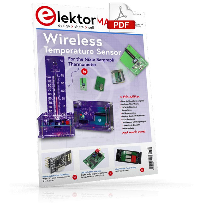
Elektor Digital Elektor September/October 2020 (PDF) EN
USB to S/PDIF InterfaceDigital audio output for computer, laptop, tablet or smartphone Practical ESP32 Multitasking (4)Binary semaphores A Wireless Temperature Sensor for the Nixie Bargraph ThermometerA multipurpose solution with a design trick Multitasking with Raspberry PiShowcase: a traffic lights controller Timer for Headphone Amplifier Open-Network Weather Station Mk.2Part 2: Software Home Automation Made EasyWith ESPHome, Home Assistant & MySensors The Storage CRTPeculiar Parts, the series Artificial Intelligence for Beginners (3)A stand-alone neural network Programming PICs from the Ground UpAssembler routine to output a sine wave IKEA Lamp HackEquipping an inexpensive IKEA lamp with NeoPixel LEDs and WLAN Don't Let Your Hobby Project Collect Dust in a CornerSupply-side time management and spiral development Starting Out in Electronics (4)Easier than imagined! Homelab Tours: The Vinyl CutterReturning to the golden age of LPs The 8-Bit Microcontroller and BeyondInterview with Tam Hanna Small Circuits RevivalFrom the Elektor suggestions box Review: Owon OW18E Bluetooth Multimeter InteractiveCorrections & Updates || Questions & Answers Steeped in ElectronicsLead-free soldering and EU regulatory zeal Promising Project: New 50 Hz – 2 MHz LCR meterAccuracy and ease of use Error AnalysisTips on FMEA, High Current, and More Developer's ZoneTips & Tricks, Best Practices and Other Useful Information Review: Siglent SDL1020X Programmable DC Electronic Load High-Voltage Power Supply with Curve TracerGenerate voltages up to 400 V and trace characteristics curves for valves and transistors Hexadoku 2009EL Analogue Electronics DesignCase Study #2 — Part 1: Analogue filter theory The Elektor StoreNever expensive, always surprising How to Draw a Circuit Diagram
€ 7,50
-
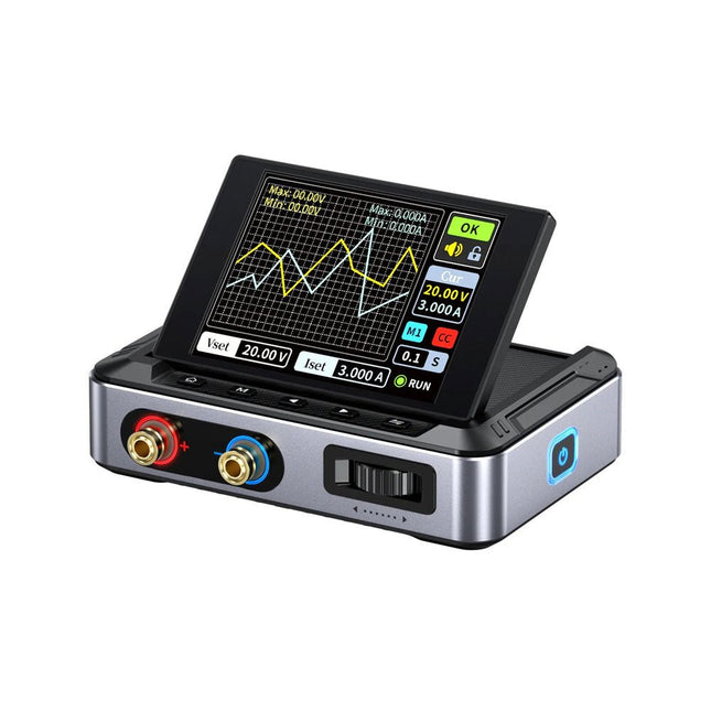
FNIRSI FNIRSI DPS150PD DC Power Supply (150 W)
The FNIRSI DPS150 is a high-performance adjustable DC power supply that features a USB-C input interface and multiple power supply modes, allowing precise adjustment of output voltage (0-30 V) and current (0-5 A). It provides efficient, low-consumption, and stable output, equipped with multiple safety protection functions including overvoltage, overcurrent, overload, overheating, and reverse connection. It can be flexibly applied to serial connection of multiple devices, with rich and user-friendly display and operation, compact and portable design, meeting various application needs. Features 30 V, 5 A, 150 W variable DC power with 0.01 V, 0.001 A precision, CC/CV modes, and <20 mV ripple to protect sensitive electronics. Supports PC, QC, and DC inputs with programmable outputs and 6 preset voltage/current settings. Compatible with 4 mm banana plugs, U-shaped terminals, and copper wires for various equipment. 8 safety mechanisms including overvoltage, current, short circuit, and overheating protection. 2.8-inch HD IPS screen with 90° flip, numerical and curve displays for easy monitoring. Small, space-saving design for use in labs, repairs, and DIY projects. Specifications Input Voltage 5~32 V DC Input Current 100 mA-5 A Output Voltage 0-30 V Output Current 0~5 A Output Power 0-150 W Input Way PD fast charger QC fast charger Power bank DC power adapters Operating Environment 0-40°C Load Regulation 0.49% Full Load Efficiency 96.30% Display 2.8 inch (320 x 240) Dimensions 106 x 76 x 28 mm Weight 178 g Included 1x DPS150 Power Supply 2x Alligator clip wires (black & red) 1x C2C PD charging cable 1x 100 W PD GaN Adapter (EU) 1x Micro USB cable 1x Manual Downloads Manual Firmware V0.0.1
€ 95,00
-
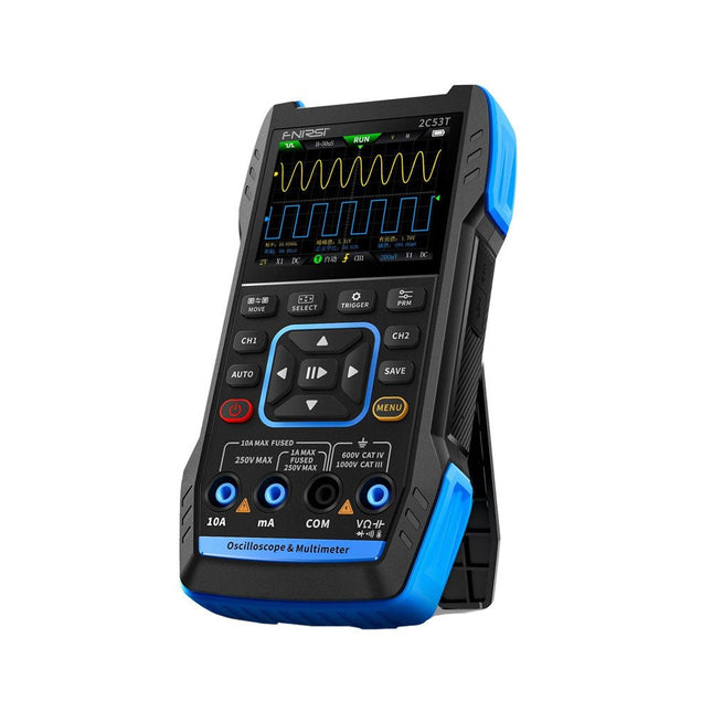
FNIRSI FNIRSI 2C53T (3-in-1) 2-ch Oscilloscope (50 MHz) + Multimeter + Signal Generator
The FNIRSI 2C53T, an enhanced version of its 10 MHz predecessor, is a compact and versatile 3-in-1 device. It combines a dual-channel 50 MHz oscilloscope, a 4.5-digit True RMS multimeter, and a signal generator with 13 waveform types, making it an essential tool for maintenance and research professionals. Oscilloscope: Features 50 MHz bandwidth, 250 MS/s sampling rate, ±400 V protection, FPGA + ARM + ADC architecture, and waveform saving for analysis. Multimeter: 4.5-digit True RMS with 19999 counts, supports AC/DC voltage, current, capacitance, resistance, diode, and continuity measurements. Signal Generator: Outputs 13 signal types up to 50 KHz, with adjustable frequency, amplitude, and duty cycle. With a 2.8-inch LCD, 3000 mAh battery (6-hour runtime), and a portable design, it delivers powerful functionality in a user-friendly package. Specifications Oscilloscope Channels 2 Analog Bandwidth 50 MHz Real-time Sampling Rate 250 MS/s Storage Depth 1 Kpts Impedance 1 MΩ Time Base Range 10ns-20s Vertical Sensitivity 10 mV/div-10 V/div (x1) Maximum Measured Voltage ±400 V Trigger Mode Auto/Normal/Single Trigger Type Rising edge, Falling edge Display Mode Y-T/Rolling/X-Y Coupling Method AC/DC Persistence OFF, 500ms, 1s, ∞ Math 8 Basic Operations + FFT Supported Waveform Screenshot Save, Export Waveform Image, Cursor Measurement, Infinite Afterglow Multimeter DC Voltage 1.9999V/19.999V/199.99V/1000V ±(0.5%+3) AC Voltage 1.9999V/19.999V/199.99V/750.0V ±(1%+3) DC Current 19.999mA/199.99mA/1.9999A/9.999A ±(1.2%+3) AC Current 19.999mA/199.99mA/1.9999A/9.999A ±(1.5%+3) Resistance 19.999MΩ/1.9999MΩ/199.99KΩ/19.999KΩ ±(0.5%+3) 1.9999KΩ/199.99Ω ±(2.0%+3) Capacitance 999.9uF/99.99uF/9.999uF/999.9nF/99.99nF/9.999nF ±(2.0%+5) 9.999mF/99.99mF ±(5.0%+20) Temperature −55~1300°C (−67~2372°F) ±(2.5%+5) Continuity Test Yes Diode Yes Signal Generator 13 Signal Waveforms Sine wave, rectangular wave, sawtooth wave, half wave, full wave, positive step wave, reverse step wave, exponential rise, exponential fall, DC, multi-audio, Sinker pulse, Lorentz wave Output Frequency 0-50 KHz Output Amplitude 0-3 V Output Duty Cycle 0-100% General Display 2.8" HD color screen Resolution 320 x 240 Charging USB-C (5 V/1 A) Battery 3000 mAh Lithium battery Standby Time 6 hours Languages English, Chinese Dimensions 167 x 89 x 35 mm Weight 300 g Differences New vs Old Version Model 2C53T Upgrade 2C53T Predecessor Bandwidth 50 MHz 10 MHz Display Mode Y-T/Rolling/X-Y Y-T/Rolling Math 8 Basic Operations + FFT N/A Cursor Function Yes N/A XY Lissau Graph Yes N/A Afterglow Function Yes N/A Multimeter Accuracy 19999 Counts 9999 Counts Signal Generator 50 KHz 2 MHz Included 1x FNIRSI 2C53T Oscilloscope (50 MHz) 2x P6100 Oscilloscope probes (10X) 1x Multimeter probe 1x Alligator clip probe 1x USB-C charging cable 1x Storage bag 1x Manual Downloads Manual Firmware V1.2.0
-
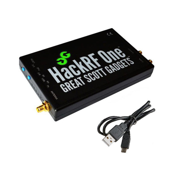
Great Scott Gadgets Great Scott Gadgets HackRF One SDR (1 MHz – 6 GHz)
New Version available! Click here! HackRF One is a Software Defined Radio (SDR) peripheral capable of transmission or reception of radio signals from 1 MHz to 6 GHz. Designed to enable test and development of modern and next generation radio technologies, HackRF One is an open source hardware platform that can be used as a USB peripheral or programmed for stand-alone operation. Specifications 1 MHz to 6 GHz operating frequency Half-duplex transceiver Up to 20 million samples per second 8-bit quadrature samples (8-bit I and 8-bit Q) Compatible with GNU Radio, SDR and more Software-configurable RX and TX gain and baseband filter Software-controlled antenna port power (50 mA at 3.3 V) SMA female antenna connector SMA female clock input and output for synchronization Convenient buttons for programming Internal pin headers for expansion Hi-Speed USB 2.0 USB-powered Open source hardware HackRF One is test equipment for RF systems. It has not been tested for compliance with regulations governing transmission of radio signals. You are responsible for using your HackRF One legally. Included 1x HackRF One SDR 1x Plastic enclosure 1x micro-USB cable Note: An antenna is not included. ANT500 is recommended as a starter antenna for HackRF One. Downloads Documentation GitHub Source code and hardware design files
-

Elektor Labs Elektor Dual DC LISN (150 kHz – 200 MHz)
Measuring conducted emission is the simplest and most affordable method of getting some indication of whether a design can meet EMI/EMC requirements. A Line Impedance Stabilization Network (LISN) is an indispensable part of an EMC pre-compliance test setup. In cooperation with Würth Elektronik, Elektor has developed a 5 µH, 50 Ω Dual DC LISN that supports voltages up to 60 V and currents up to 10 A. The instrument measures RF interferences on both channels (the power supply) by means of 5-μH blocking inductances. The internal 10-dB attenuation network – one in each channel – contains a 3rd-order high-pass filter with a cutoff frequency of 9 kHz to protect the input of instruments like a spectrum analyzer from potentially harmful DC voltages or low frequencies coming from the EUT (Equipment Under Test). Specifications RF path Channels 2 (with clamping diodes) Bandwidth 150 kHz – 200 MHz Inductance 5 μH || 50 Ω Internal attenuation 10 dB Connectors SMA DC path Max. current < 10 ADC Max. voltage < 60 VDC DC resistance < 2 x 70 mΩ PCB size 94.2 x 57.4 mm Connectors 4-mm banana Hammond enclosure Type 1590N Dimensions 121 x 66 x 40 mm Included 1x 4-layer PCB with all SMT parts fitted 1x pre-drilled enclosure with ready-printed front panel layout 5x gold-plated, insulated, 4-mm banana sockets, rated for 24 A, 1 kV 1x Hammond enclosure 1590N1, Aluminum (Die-Cast Alloy) More Info Project on Elektor Labs: Dual DC LISN for EMC pre-compliance testing Elektor 9-10/2021: EMC Pre-Compliance Test for Your DC-Powered Project (Part 1) Elektor 11-12/2021: EMC Pre-Compliance Test for Your DC-Powered Project (Part 2)
-
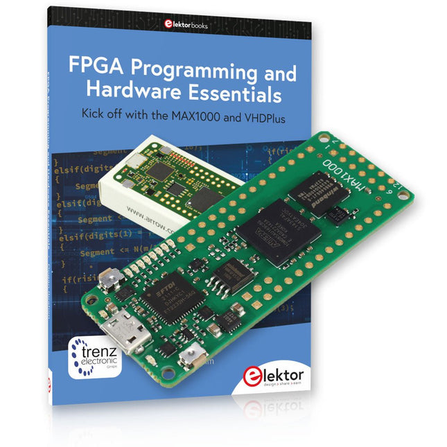
Elektor Bundles MAX1000 FPGA Programming Bundle
Kick off to FPGA Programming with the MAX1000 Board and VHDPlus Ready to master FPGA programming? With this bundle, you'll dive into the world of Field-Programmable Gate Arrays (FPGAs) – a configurable integrated circuit that can be programmed after manufacturing. Bring your ideas to life, from simple projects to complete microcontroller systems! The MAX1000 is a compact and powerful FPGA development board packed with features like memory, user LEDs, push-buttons, and flexible I/O ports. It’s the ideal starting point for anyone wanting to learn about FPGAs and Hardware Description Languages (HDLs). With the enclosed book "FPGA Programming and Hardware Essentials" you'll get hands-on with the VHDPlus programming language – a simpler version of VHDL. You'll work on practical projects using the MAX1000, helping you gain the skills and confidence to unleash your creativity. Projects in the Book Arduino-driven BCD to 7-Segment Display Decoder Use an Arduino Uno R4 to supply BCD data to the decoder, counting from 0 to 9 with a one-second delay Multiplexed 4-Digit Event Counter Create an event counter that displays the total count on a 4-digit display, incrementing with each button press PWM Waveform with Fixed Duty Cycle Generate a PWM waveform at 1 kHz with a fixed duty cycle of 50% Ultrasonic Distance Measurement Measure distances using an ultrasonic sensor, displaying the results on a 4-digit 7-segment LED Electronic Lock Build a simple electronic lock using combinational logic gates with push buttons and an LED output Temperature Sensor Monitor ambient temperature with a TMP36 sensor and display the readings on a 7-segment LED MAX1000 FPGA Development Board The MAX1000 is a customizable IoT/Maker Board ready for evaluation, development and/or use in a product. It is built around the Intel MAX10 FPGA, which is the industry’s first single chip, non-volatile programmable logic device (PLDs) to integrate the optimal set of system components. Users can now leverage the power of tremendous re-configurability paired with a high-performance, low-power FPGA system. Providing internally stored dual images with self-configuration, comprehensive design protection features, integrated ADCs and hardware to implement the Nios II 32-bit microcontroller IP, MAX10 devices are ideal solution for system management, protocol bridging, communication control planes, industrial, automotive and consumer applications. The MAX1000 is equipped with an Arrow USB Programmer2, SDRAM, flash memory, accelerometer sensor and PMOD/Arduino MKR connectors making it a fully featured plug and play solution without any additional costs. Specifications MAX 10 8 kLE - Flash Dual inside - ADC 8x 12 Bit - Temperature Range 0~85°C - Supply USB/pins SDRAM 8 MB 3-axis MEMS LIS3DH USB Programmer on board MEMS Oscillator 12 MHz Switch/LED 2x / 8x Contents of the Bundle Book: FPGA Programming and Hardware Essentials (normal price: €40) MAX1000 FPGA Development Board (normal price: €45) Downloads Software


