Aus der Reihe "Stromversorgung ohne Stress" (Band 3)
Elektronik ohne Batterien oder Versorgungsnetz
Für den Betrieb moderner elektronischer Bauteile ist vergleichsweise nur noch wenig Energie notwendig. Dies eröffnet neue Möglichkeiten, wie z. B. Schaltungen und Baugruppen, die ohne Batterien oder Akkumulatoren auskommen und auch keinen Anschluss an das Versorgungsnetz benötigen. Damit entfällt auch ein großer Teil des Wartungsaufwandes. Die Baugruppen arbeiten weitestgehend „für sich alleine“. Die Energie wird auf unterschiedlichste Weise aus der Umgebung gewonnen. Dazu sind allerdings spezielle Techniken erforderlich. Nicht nur zur Gewinnung der Energie – auch zur Umformung, so dass sie für elektronische Schaltungen nutzbar ist.
In diesem Buch geht es um die Bereitstellung kleiner Energiemengen, mit denen kleine Geräte (Sensoren, Sender und Empfänger für QRP oder Datenübertragung, etc.) völlig autark betrieben werden können – wenn möglich, mit Bauteilen aus der Bastelkiste und ohne komplexe, spezialisierte Integrierte Schaltungen.
Die am Thema interessierten Elektroniker und „Macher“ lernen hier, wie sie eigene reale Energy-Harvesting-Projekte mit Teilen aus der Bastelkiste umsetzen können, ohne vorher viel Zeit für lange theoretische Abhandlungen aufzubringen.
Gerade beim Energy Harvesting ist es jedoch nicht immer möglich auf Spezial–ICs zu verzichten. Es geht eben um jedes µW und es ist leicht nachvollziehbar, dass es einfacher ist, auf einer kleinen Chipfläche mit wenig Energie zu arbeiten, als bei einer ausladenden Schaltung mit umfangreicher Verdrahtung.
Die mehr „theoretischen“ oder grundsätzlichen Themen wurden in die einzelnen Kapitel und Projekte eingestreut. Den vollständigen Überblick erhält man deshalb erst, wenn man das Buch in Gänze gelesen hat. Dafür kann der Leser bereits im 2. Kapitel ein erstes Projekt umsetzen.
Elektor GREEN and GOLD members can download their digital edition here.
Not a member yet? Click here.
A Current Source for Testing (Z-)DiodesChecking Z-Diodes from 1 to 54 V @ 1 to 50 mA
ESD Strap TesterA Bench Tool with Pass, Borderline, and Fail Indication
Power Supply Transient Response TesterA Repeatable Step-Load Generator for Bench Power Supplies
Euclidean Sequencer Without a MicrocontrollerTrigger Patterns and CV Sequences with Simple CMOS Logic
LED Flashing Light for Gates and More with an Audible Alert
Need PCBs? The Elektor PCB Service Has You Covered.
Toothbrush TimerUsing a Tiny PIC
A Contactless Magnetic Combination LockWith the AS5600 Rotary Position Sensor
Low-Noise Battery-Powered PreamplifierFor Dynamic Microphones
The Arduino Nano TestLabMeasurement, Control, and Regulation
Rhythmic Bass LightEmphasize the Rhythm of Your Music
Low-Cut FilterNo Risk of Audio Feedback on Your System
Precise 1 Hz Square Wave Generator for BreadboardsA Reliable CMOS-Based Clock Source
555 Upside DownDuty Cycles Down to Zero
From Halfgeleidergids to Circuit Specials65 Years of Electronics Innovation
Electrical IsolationCAN Interface with Digital Isolator and Power Module
SpongillatorA Sponge-Based Oscillator
True Random Number GeneratorWith Integrated Chi-Square Test
3D Viewer for HTML pagesSimple, and Almost Without Code
Programming with TLScriptA Scripting Language for Measurement, Testing, and Control
Circuit Design: Tips from Experts
FeedbackWhat Is It and Why Is It Important?
One Board, Endless Ideas: Arduino UNO QFrom Retro Gaming to Real-Time Environmental Monitoring
How to Fix a Donut Antenna
Standby KillerA Real On/Off Switch for Your TV
Battery TestingMeasuring Batteries with the Arduino Nano
Power Supply for Audio Power AmplifiersA Good Power Supply Without Mains Hum
Prototyping Boards for RFFast Setups with DIY Prototyping Boards
T3 Surge ProtectionA Type 3 Spike Suppressor for Your Sensitive Equipment
IoT Room Thermostat BoardWith ESP32-C3/S3-Based Xiao MCU module
From Rigid to SmartFlexible and Printed Electronics — Between Vision and Industrial Reality
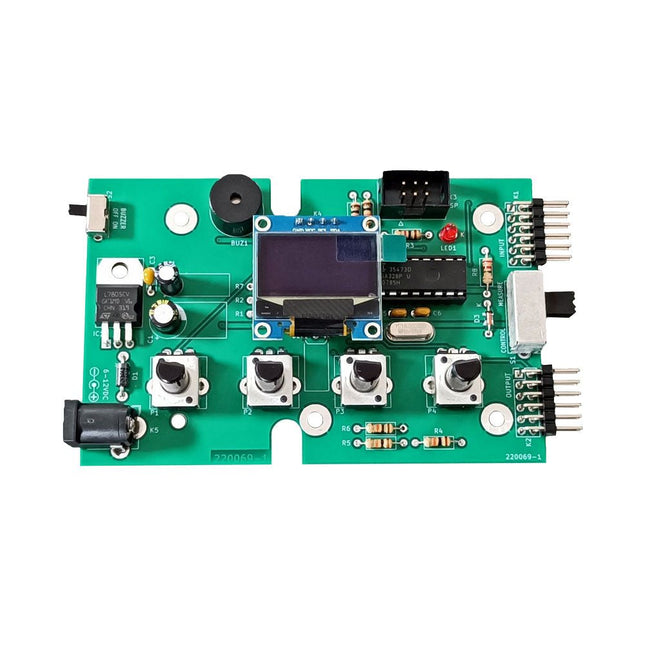
The Elektor Super Servo Tester can control servos and measure servo signals. It can test up to four servo channels at the same time.
The Super Servo Tester comes as a kit. All the parts required to assemble the Super Servo Tester are included in the kit. Assembling the kit requires basic soldering skills. The microcontroller is already programmed.
The Super Servo Tester features two operating modes: Control/Manual and Measure/Inputs.
In Control/Manual mode the Super Servo Tester generates control signals on its outputs for up to four servos or for the flight controller or ESC. The signals are controlled by the four potentiometers.
In Measure/Inputs the Super Servo Tester measures the servo signals connected to its inputs. These signals may come from for instance an ESC, a flight controller, or the receiver or another device. The signals are also routed to the outputs to control the servos or the flight controller or ESC. The results are shown on the display.
Specifications
Operating modes
Control/Manual & Measure/Inputs
Channels
3
Servo signal inputs
4
Servo signal outputs
4
Alarm
Buzzer & LED
Display
0.96' OLED (128 x 32 pixels)
Input voltage on K5
7-12 VDC
Input voltage on K1
5-7.5 VDC
Input current
30 mA (9 VDC on K5, nothing connected to K1 and K2)
Dimensions
113 x 66 x 25 mm
Weight
60 g
Included
Resistors (0.25 W)
R1, R3
1 kΩ, 5%
R2, R4, R5, R6, R7, R9, R10
10 kΩ, 5%
R8
22 Ω, 5%
P1, P2, P3, P4
10 kΩ, lin/B, vertical potentiometer
Capacitors
C1
100 µF 16 V
C2
10 µF 25 V
C3, C4, C7
100 nF
C5, C6
22 pF
Semiconductors
D1
1N5817
D2
LM385Z-2.5
D3
BZX79-C5V1
IC1
7805
IC2
ATmega328P-PU, programmed
LED1
LED, 3 mm, red
T1
2N7000
Miscellaneous
BUZ1
Piezo buzzer with oscillator
K1, K2
2-row, 12-way pinheader, 90°
K5
Barrel jack
K4
1-row, 4-way pin socket
K3
2-row, 6-way boxed pinheader
S1
Slide switch DPDT
S2
Slide switch SPDT
X1
Crystal, 16 MHz
28-way DIP socket for IC2
Elektor PCB
OLED display, 0.96', 128 x 32 pixels, 4-pin I²C interface
Links
Elektor Magazine
Elektor Labs
Kick off with the MAX1000 and VHDPlus
Ready to Master FPGA Programming? In this guide, we’re diving into the world of Field Programmable Gate Arrays (FPGAs) – a configurable integrated circuit that can be programmed after manufacturing. Imagine bringing your ideas to life, from simple projects to complete microcontroller systems!
Meet the MAX1000: a compact and budget-friendly FPGA development board packed with features like memory, user LEDs, push-buttons, and flexible I/O ports. It’s the ideal starting point for anyone wanting to learn about FPGAs and Hardware Description Languages (HDLs).
In this book, you’ll get hands-on with the VHDPlus programming language – a simpler version of VHDL. We’ll work on practical projects using the MAX1000, helping you gain the skills and confidence to unleash your creativity.
Get ready for an exciting journey! You’ll explore a variety of projects that highlight the true power of FPGAs. Let’s turn your ideas into reality and embark on your FPGA adventure – your journey starts now!
Exciting Projects You’ll Find in This Book
Arduino-Driven BCD to 7-Segment Display Decoder
Use an Arduino Uno R4 to supply BCD data to the decoder, counting from 0 to 9 with a one-second delay
Multiplexed 4-Digit Event Counter
Create an event counter that displays the total count on a 4-digit display, incrementing with each button press
PWM Waveform with Fixed Duty Cycle
Generate a PWM waveform at 1 kHz with a fixed duty cycle of 50%
Ultrasonic Distance Measurement
Measure distances using an ultrasonic sensor, displaying the results on a 4-digit 7-segment LED
Electronic Lock
Build a simple electronic lock using combinational logic gates with push buttons and an LED output
Temperature Sensor
Monitor ambient temperature with a TMP36 sensor and display the readings on a 7-segment LED
Downloads
Software
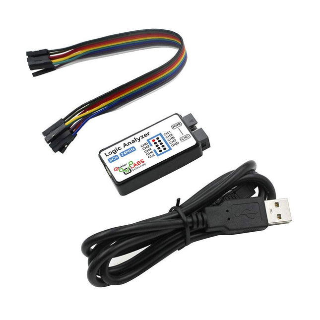
This USB Logic Analyzer is an 8-channel logic analyzer with each input dual purposed for analog data recording. It is perfect for debugging and analyzing signals like I²C, UART, SPI, CAN and 1-Wire. It operates by sampling a digital input connected to a device under test (DUT) at a high sample rate. The connection to the PC is via USB.
Specifications
Channels
8 digital channels
Maximum sampling rate
24 MHz
Maximum input voltage
0~5 V
Operating temperature
0~70°C
Input impedance
1 MΩ || 10 pF
Supported protocols
I²C, SPI, UART, CAN, 1-Wire, etc.
PC connection
USB
Dimensions
55 x 28 x 14 mm
Included
USB Logic Analyzer (8-ch, 24 MHz)
USB Cable
Jumper Wire Ribbon Cable
Downloads
Software
Pull Down Lever For Highest Score!
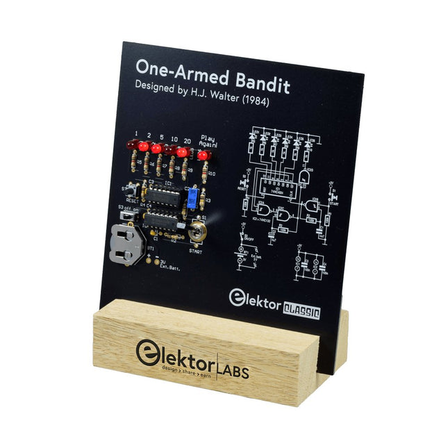
This Elektor Circuit Classic from 1984 shows a playful application of CMOS 400x series logic ICs in combination with LEDs, a highly popular combination at the time. The project imitates a spinning-digit type slot machine.
The Game
To play the game, first agree on the number of rounds. Player 1 actuates the switch lever as long as desired and releases it. The LEDs then show the score which is the sum of the 50-20-10-5 digits lit up. If the Play Again! LED lights, Player 1 has another, “free” round. If not, it’s Player 2’s turn. The players keep tab of their scores, and the highest score wins.
Features
LEDs Indicate Score
Multi-Player and Play Again!
Elektor Heritage Circuit Symbols
Tried & Tested by Elektor Labs
Educational & Geeky Project
Through-Hole Parts Only
Included
Printed Circuit Board
All Components
Wooden Stand
Bill of Materials
Resistors (5%, 250 mW)
R1,R2,R3,R4 = 100kΩ
R5,R6,R7,R8,R9,R10 = 1kΩ
Capacitors
C1 = 4.7nF, 10%, 50V, 5mm
C2 = 4.7μF, 10%, 63V, axial
C3,C4 = 100nF, 10 %, 50V, ceramic X7R, 5mm
Semiconductors
LED1-LED6 = red, 5mm (T1 3/4)
IC1 = 74HC4024
IC2 = 74HC132
Miscellaneous
S1 = switch, toggle, 21mm lever, SPDT, momentary
S2 = switch, tactile, 24V, 50mA, 6x6mm
S3 = switch, slide, SPDT
IC1,IC2 = IC socket, DIP14
BT1 = PCB-mount CR2032 battery retainer clip
Desktop Stand
PCB 230098-1
Not included: BT1 = CR2032 coin cell battery
Realize your own projects with the Elektor Arduino Nano MCCAB Training Board
The microcontroller is probably the most fascinating subfield of electronics. Due to the multitude of functions, it combines on its chip, it is a universal multi-tool for developers to realize their projects. Practically every device of daily use today is controlled by a microcontroller. However, for an electronic layman, realizing his own ideas with a microcontroller has so far remained a pipe dream due to its complexity. The Arduino concept has largely simplified the use of microcontrollers, so that now even laymen can realize their own electronics ideas with a microcontroller.
Book & Hardware in the Bundle: 'Learning by Doing'
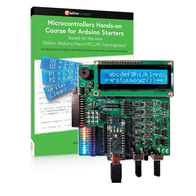
This book, which is included in the bundle, shows how you can realize your own projects with a microcontroller even without much experience in electronics and programming languages. It is a microcontrollers hands-on course for starters, because after an overview of the internals of the microcontroller and an introduction to the programming language C, the focus of the course is on the practical exercises. The reader acquires the necessary knowledge by 'learning by doing': in the extensive practical section with 12 projects and 46 exercises, what is learned in the front part of the book is underpinned with many examples. The exercises are structured in such a way that the user is given a task to solve using the knowledge built up in the theoretical part of the book. Each exercise is followed by a sample solution that is explained and commented on in detail, which helps the user to solve problems and compare it with his own solution.
Arduino IDE
The Arduino IDE is a software development environment that can be downloaded for free to your own PC and that contains the entire software package needed for your own microcontroller projects. You write your programs ('apps') with the IDE’s editor in the C programming language. You translate them into the bits and bytes that the microcontroller understands using the Arduino IDE's built-in compiler, and then load them into the microcontroller's memory on the Elektor Arduino MCCAB Nano Training Board via a USB cable.
Query or control external sensors, motors or assemblies
In addition to an Arduino Nano microcontroller module, the Elektor Arduino Nano MCCAB Training Board contains all the components required for the exercises, such as light-emitting diodes, switches, pushbuttons, acoustic signal transmitters, etc. External sensors, motors or assemblies can also be queried or controlled with this microcontroller training system.
Specifications (Arduino Nano MCCAB Training Board)
Power Supply
Via the USB connection of the connected PC or an external power supply unit (not included)
Operating Voltage
+5 Vcc
Input Voltage
All inputs
0 V to +5 V
VX1 and VX2
+8 V to +12 V (only when using an external power supply)
Hardware periphery
LCD
2x16 characters
Potentiometer P1 & P2
JP3: selection of operating voltage of P1 & P2
Distributor
SV4: Distributor for the operating voltagesSV5, SV6: Distributor for the inputs/outputs of the microcontroller
Switches and buttons
RESET button on the Arduino Nano module 6x pushbutton switches K1 ... K6 6x slide switches S1 ... S6 JP2: Connection of the switches with the inputs of the microcontroller
Buzzer
Piezo buzzer Buzzer1 with jumper on JP6
Indicator lights
11 x LED: Status indicator for the inputs/outputs LED L on the Arduino Nano module, connected to GPIO D13 JP6: Connection of LEDs LD10 ... LD20 with GPIOs D2 ... D12
Serial interfacesSPI & I²C
JP4: Selection of the signal at pin X of the SPI connector SV12 SV9 to SV12: SPI interface (3.3 V/5 V) or I²C interface
Switching output for external devices
SV1, SV7: Switching output (maximum +24 V/160 mA, externally supplied) SV2: 2x13 pins for connection of external modules
3x3 LED matrix(9 red LEDs)
SV3: Columns of the 3x3 LED matrix (outputs D6 ... D8) JP1: Connection of the rows with the GPIOs D3 ... D5
Software
Library MCCABLib
Control of hardware components (switches, buttons, LEDs, 3x3 LED matrix, buzzer) on the MCCAB Training Board
Operating Temperature
Up to +40 °C
Dimensions
100 x 100 x 20 mm
Specifications (Arduino Nano)
Microcontroller
ATmega328P
Architecture
AVR
Operating Voltage
5 V
Flash Memory
32 KB, of which 2 KB used by bootloader
SRAM
2 KB
Clock Speed
16 MHz
Analog IN Pins
8
EEPROM
1 KB
DC Current per I/O Pins
40 mA on one I/O pin, total maximum 200 mA on all pins together
Input Voltage
7-12 V
Digital I/O Pins
22 (6 of which are PWM)
PWM Output
6
Power Consumption
19 mA
Dimensions
18 x 45 mm
Weight
7 g
Included
Elektor Arduino Nano MCCAB Training Board
Arduino Nano
Book: Microcontrollers Hands-on Course for Arduino Starters
The FNIRSI HT-P1B Pro is a compact mini hot plate designed for PCB soldering, desoldering, and SMD rework. With up to 150 W of heating power, precise PID temperature control, and an adjustable temperature range of 100°C to 350°C, it delivers fast and stable heating for electronics projects.
The 50 x 50 mm heating surface is ideal for small PCBs and electronic components. Two operating modes – constant temperature heating and simulated reflow soldering – provide flexibility for different applications. A 1.44-inch color display, three temperature presets, and built-in safety features ensure convenient operation.
With DC and USB-C PD 3.1 support, a compact design, and an included 100 W USB-C charger, the HT-P1B Pro is a practical tool for makers, electronics enthusiasts, and repair professionals.
Features
Up to 150 W Heating Power: Fast heating with adjustable power settings from 30 W to 150 W.
Precise PID Temperature Control: Adjustable range from 100°C to 350°C with ±3°C temperature stability.
Dual Operating Modes: Constant temperature heating and simulated reflow soldering.
50 × 50 mm Heating Surface: Ideal for small PCBs, SMD soldering, and component rework.
Flexible Power Input: DC 12-28 V (up to 150 W) and USB-C PD 3.1 (up to 140 W).
Three Temperature Presets: Quick access to frequently used temperature settings.
1.44-inch Color Display: Shows temperature, voltage, power, heating time, and operating status.
Built-in Safety Features: Over-temperature, low-voltage, prolonged-heating, and tilt protection.
Specifications
Power Input
DC 12-28 V / USB-C PD
Power Range
30-150 W
Standby Power
1.6 W
Temperature Range
100-350°C (212-662°F)
Temperature Stability
±3°C
Heating Area
50 x 50 mm
Display
1.44" Color Screen
Tilt Detection
20°-50°
Protocol
PD 3.1
Dimensions
68.8 x 81.8 x 44.5 mm
Weight
157 g
Included
1x FNIRSI HT-P1B Preheating Station
1x FNIRSI 100 W PD GaN Charger (EU)
1x FNIRSI 100 W USB-C Fast-charging Cable
1x Heat-Resistant Silicone Cover
1x Storage Case
1x Manual
Downloads
Manual
The OWON SDS1102 is an affordable benchtop digital oscilloscope that combines solid performance with essential measurement features. This 2-channel oscilloscope offers a 100 MHz bandwidth, a 1 GS/s sampling rate, a 7-inch LCD display, and a 10 kpts memory depth, making it a practical choice for everyday electronics testing, troubleshooting, and education.
The SDS1102 features a simplified trigger system with level and edge triggering, making it easy to capture and analyze common signals. It is designed for applications that do not require deep memory or advanced trigger functions, offering a straightforward and cost-effective solution for basic signal analysis.
Features
Bandwidth: 100 MHz
2 channels
Sample rate: 1 GS/s
Ultra-thin body
7-inch high-res LCD
SCPI and LabVIEW supported
Specifications
Bandwidth
100 MHz
Horizontal Scale (s/div)
5 ns/div – 1000 s/div
Channel
2
Vertical Sensitivity
5 mV/div – 5 V/div (at input)
DC Gain Accuracy
3%
Vertical Resolution (A/D)
8 bits (2 channels simultaneously)
Input
Input Impedance
1 MΩ, 10 pF
Input Coupling
AC, DC, GND
Max Input Voltage
±400 V, CATI, CATII
Passive probes
х1; х10
Probe Attenuation Factor
х1; х10; х100; х1000
Trigger System
Trigger Mode
Auto, Normal, Single
Trigger Type
Edge, Video
Edge Trigger Source
CH1, CH2
Video Trigger
Sampling Type
Real-time
Sample Rate
1 GS/s
Equivalent Sample Rate
No
Wavelength
10K pts
Interpolation
sin(x)/x
Measurement and Mathematical Treatment System
Automatic Measurement
Vpp, Vavg, RMS, Frequency, Period, Vmax, Vmin, Vtop, Vbase, Width, Overshoot, Pre-shootRise time, Fall time, +Width, -Width, +Duty, -Duty, Delay A→B, Delay A→B, area, cycle area
Math Functions
Addition, Subtraction, Multiplication, Division, FFT
General Characteristics
Display type
7" color LCD
Display Resolution
800 x 480
Power
100-240 V, 45-440 Hz, <15 W
Dimensions
301 x 70 x 152 mm
Weight
1.1 kg
Included
1x OWON SDS1102 Oscilloscope
2x Oscilloscope probes
1x Probe adjust
1x Mains power cord
1x USB cable
1x CD-Rom
1x Quick guide
Downloads
Quick Guide
Manual
PC Software
SCPI Commands
This hands-on bundle lets you build real Edge AI applications with the Raspberry Pi
Raspberry Pi AI HAT+ (13 TOPS)
The Raspberry Pi AI HAT+ (13 TOPS) is an expansion board designed for the Raspberry Pi 5, featuring an integrated Hailo AI accelerator. This add-on offers a cost-effective, efficient, and accessible approach to incorporating high-performance AI capabilities, with applications spanning process control, security, home automation, and robotics.
The AI HAT+ connects via the Raspberry Pi 5’s PCIe Gen3 interface. When the Raspberry Pi 5 is running a current version of the Raspberry Pi OS, it automatically detects the onboard Hailo accelerator, making the neural processing unit (NPU) available for AI tasks. Additionally, the rpicam-apps camera applications included in Raspberry Pi OS seamlessly support the AI module, automatically using the NPU for compatible post-processing functions.
Raspberry Pi Camera Module 3
Raspberry Pi Camera Module 3 is a compact camera from Raspberry Pi. It offers an IMX708 12-megapixel sensor with HDR, and features phase detection autofocus. Camera Module 3 is available in standard and wide-angle variants, both of which are available with or without an infrared cut filter.
Camera Module 3 can be used to take full HD video as well as stills photographs, and features an HDR mode up to 3 megapixels. Its operation is fully supported by the libcamera library, including Camera Module 3’s rapid autofocus feature: this makes it easy for beginners to use, while offering plenty for advanced users. Camera Module 3 is compatible with all Raspberry Pi computers.
Book: Edge AI Made Practical – AI Projects for the Raspberry Pi with the AI HAT+
Edge AI is transforming everyday devices by putting intelligence where it matters most: directly inside the hardware. With on-device inference, a camera can recognize a visitor instantly, a phone can translate speech without streaming audio to the cloud, and a wearable can detect anomalies in real time—fast, private, and reliable even when the network disappears.
This book is your practical guide to building exactly those kinds of systems with the Raspberry Pi AI HAT+ and the Hailo-8L accelerator. You’ll start with clear foundations: core AI and machine-learning concepts, how neural networks work, and what truly distinguishes Edge AI from cloud AI—plus an honest look at ethical considerations and future impacts.
This bundle contains:
Book: Edge AI Made Practical
Raspberry Pi AI HAT+ (13 TOPS)
Raspberry Pi Camera Module 3
Active Cooler for Raspberry Pi 5
FPC Display Cable for Raspberry Pi 5 (300 mm)
Elektor Component Kit
40-pin GPIO Header
Traffic Light Module
LED red 5 V with built-in resistor
LED yellow 5 V with built-in resistor
LED green 5 V with built-in resistor
LED blue 5 V with built-in resistor
Breadboard (400 Tie-points)
10 Dupont wires male-female
DHT22 sensor module
Servo motor
Required
Raspberry Pi 5
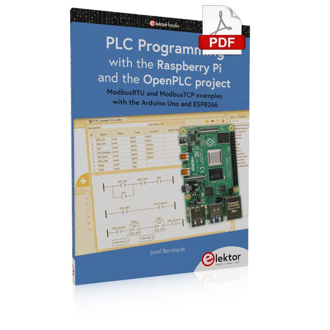
ModbusRTU and ModbusTCP examples with the Arduino Uno and ESP8266
Introduction to PLC programming with OpenPLC, the first fully open source Programmable Logic Controller on the Raspberry Pi, and Modbus examples with Arduino Uno and ESP8266
PLC programming is very common in industry and home automation. This book describes how the Raspberry Pi 4 can be used as a Programmable Logic Controller. Before taking you into the programming, the author starts with the software installation on the Raspberry Pi and the PLC editor on the PC, followed by a description of the hardware.
You'll then find interesting examples in the different programming languages complying with the IEC 61131-3 standard. This manual also explains in detail how to use the PLC editor and how to load and execute the programs on the Raspberry Pi. All IEC languages are explained with examples, starting with LD (Ladder Diagram) over ST (Structured Control Language) to SFC (Special Function Chart). All examples can be downloaded from the author's website.
Networking gets thorough attention too. The Arduino Uno and the ESP8266 are programmed as ModbusRTU or ModbusTCP modules to get access to external peripherals, reading sensors and switching electrical loads. I/O circuits complying with the 24 V industry standard may also be of interest for the reader.
The book ends with an overview of commands for ST and LD. After reading the book, the reader will be able to create his own controllers with the Raspberry Pi.
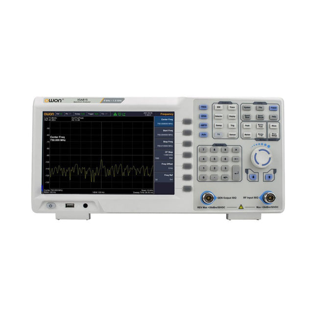
The OWON XSA815-TG (9 kHz-1.5 GHz) is a cost effective spectrum analyzer with tracking generator included and a frequency resolutions of 1 Hz.
Features
Frequency Range from 9 kHz to 1.500009 GHz
9-inch display
9 kHz to 1 MHz -95 dBm Displayed Average Noise Level, 1 MHz to 500 MHz 140 dBm (Typical), <-130 dBm
Phase Noise
-10 kHz <-80 dBc/Hz
100 kHz <-100 dBc/Hz
1 MHz <-115 dBc/Hz
Resolution Bandwidth (-3 dB): 1 Hz to 1 MHz, in 1-3-5-10 sequence
Tracking Generator Kit: 100 kHz to 1.500009 GHz
Specifications
Frequency Range
9 kHz to 500.009 MHz
Frequency Resolution
1 Hz
Frequency Span
9 kHz to 1.500009 GHz
Span Range
0 Hz, 100 Hz to max frequency of instrument
Span Uncertainty
±span / (sweep points-1)
SSB Phase Noise (20°C to 30°C, fc=1 GHz)
Carrier Offset
10 kHz <-80 dBc/Hz | 100 kHz <-100 dBc/Hz | 1 MHz <-115 dBc/Hz
Resolution Bandwidth (-3 dB)
1 Hz to 1 MHz, in 1-3-5-10 sequence
RBW Accuracy
<5% typical
Resolution Filter Shape Factor (60 dB: 3 dB)
<5 typical
Video Bandwidth (-3 dB)
10 Hz to 1 MHz, in 1-3-5-10 sequence
Amplitude measurement range
DANL to +10 dBm, 100 kHz to 10 MHz, Preamp Off
DANL to +20 dBm, 10 MHz to 1.5 GHz, Preamp Off
Reference Level
-80 dBm to +30 dBm, 0.01dB by step
Preamp
20 dB, nominal, 100 kHz to 1.5 GHz
Input Attenuator
0 to 40 dB, 1 dB by step
Display Average Noise Level Input attenuation = 0 dB, RBW = VBW = 100 Hz, sample detector, trace average ≥ 50, 20°C to 30°C, input impedance = 50 Ω)
Preamp Off 9 kHz to 1 MHz
-95 dBm (Typical), <-88 dBm
Preamp Off 1 MHz to 500 MHz
-140 dBm (Typical), <-130 dBm
Preamp On 100 kHz to 1 MHz
-135 dBm (Typical), <-128 dBm
Preamp On 1 MHz to 500 MHz
-160 dBm (Typical),<-150 dBm
Tracking Generator (optional)
Frequency Range
100 kHz to 1.500009 GHz
Output power level range
-40 dBm to 0 dBm
Output level resolution 1 dB
Output flatness
Relative to 50 MHz | ±3 dB
Tracking generator spurious
Harmonic spurious -30 dBc (Tracking generator output power -10 dBm)
Non-harmonic spurious -40 dBc (Tracking generator output power -10 dBm)
Tracking generator to input terminal isolation
-60 dB (Tracking generator output power 0 dBm)
Tracking generator to input terminal isolation
-60 dB (Tracking generator output power 0 dBm)
Tracking generator to input terminal isolation
-60 dB (Tracking generator output power 0 dBm)
Dimensions
375 x 185 x 120 mm
Weight
3.7 kg
Included
1x XSA815-TG
1x 220 V AC power cord
1x USB Cable
1x Quickstart guide
Downloads
Quick Guide
Specifications