
Search results for "platino OR signal OR generator OR 130407 OR 1"
-
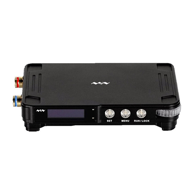
Miniware Miniware MDP-P906 Digital Power Supply (300 W)
MDP-P906 has a built-in cooling fan, and maximum output power of up to 300 W, which meets a wider range of testing needs and application scenarios. Through 2.4 GHz wireless communication, it can be connected to MDP-M01 Smart Digital Monitor module to realize the free combination of multiple channels of 300 W per channel. MDP-P906 has the index, stability and reliability comparable to a professional power supply. It can output pure current, and provide powerful functions such as programmable output, timing output, timing control, automatic compensation, boost mode, etc., making itself a real cost-effective, smart and customized programmable linear DC power supply. MDP-P906 adopts a precision CNC machined aluminum alloy shell, with fine workmanship, novel, mini and beautiful appearance, it completely subverts the rigid image of traditional desktop power supply. With stackable modular design and wireless communication function, MDP-P906 can work independently or paired, both on the workbench, and be carried out for on-site maintenance. MDP-P906 is a perfect solution for electronic engineer, especially field application engineers to meet different needs of power sources. Built-in silent cooling fan, instant cooling, ensure a stable and efficient output! Smart linear compensation, constant voltage & constant current Positive & negative output, series boost, parallel current sharing Applications Universal tests and teaching experiments in R&D laboratory Maintenance of digital products Property verification and fault diagnosis of devices and circuits Emergency power supply for model airplanes and vehicles Power supply testing of RF and microwave circuits or modules Quality control and quality inspection Supply purified power for high-accuracy digital-analog hybrid circuits and Hi-Fi audio devices Specifications Input DC 4.2-30 V/14 A (Max)QC 3.0/PD2.0, 20 V/5 A (Max) Output 0-30 V/0-10 A, 300 W (Max) Conversion efficiency 95% Output resolution 10 mV/2 mA, up to 1 mV/1 mA via Display Control module Output accuracy 0.03%+5 mV0.05%+2 mV Adjustment rate Load adjustment rate <±0.01%Power adjustment rate <±0.01% Ripple and noise <250 uVrms, 3 mVpp; 2 mArms Transient response <4 uS Safety protections Input over-voltage, under-voltage, reverse connection protection, output over-current, back-flow protection and over-temperature protection Others Automatically shut-down and enter micro-power modeSupport USB firmware upgrade Dimensions 112 x 66 x 20 mm Weight 181 g Included 1x MDP-P906 Digital Power Supply 2x Output Cable 1x User Manual Downloads User Manual v1.1 Firmware v1.32
€ 171,95
-

Elektor Digital Elektor Mai/Juin 2025 (PDF) FR
Le téléchargement intégral de ce numéro est disponible pour nos membres GOLD et GREEN sur le site Elektor Magazine ! Pas encore membre ? Cliquez ici. PbMonitor v1.0Un système de surveillance des batteries pour les applications à onduleurs et de stockage d'énergie contrôleur de charge solaire avec MPPT (1)Principes de base d'un contrôleur de charge solaire pour les systèmes autonomes magnétomètre à intégration du champ et capteurs artisanaux exactitude, ou précision ?vos appareils doivent posséder les deux ! AD7124 : un C/AN de précision en pratiqueFeatures for Sensor Signal Conditioning outil de contrôle PIDOptimisez facilement vos paramètres embedded world 2025 démarrer en électronique...…contrôle de la tonalité Academy Pro BoxLivre + cours en ligne + matériel adaptateur Milliohm-mètreUtilisant la précision de votre multimètre Un nouveau jalon dans le domaine des semi-conducteursEn route vers le 1,4 nm Connecteurs à technologie traversanteLe meilleur des deux mondes : THR fréquencemètrePortable et auto-calibré par GPS compteurs analogiquesDrôles de composants, la série testeur de quartz autonomeQuelle est la précision de votre source d'horloge ? testeur I²C peu couteuxconnecter des appareils I²C directement à votre PC sur le vifbienvenue chez les Pt’tites 2025 : une odyssée de l'IAL'impact transformateur sur le développement de logiciels projet 2.0Corrections, mises à jour, et courrier des lecteurs synthétiseur MIDI autonome Raspberry Pi (2)Améliorons notre configuration avec l’Intelligence oscillateur à pont de Wien "nortonisé"Petite cause, grand effet tester un microcontrôleur à 0,10 $Le microcontrôleur CH32V003 RISC-V et MounRiver Studio en pratique un lecteur audio avec égaliseur basé sur un FPGA (2)Ajout d'un réglage du volume, d'un mixage avancé et d'une interface Web
€ 10,95
-
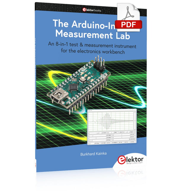
Elektor Digital The Arduino-Inside Measurement Lab (E-book)
An 8-in-1 test & measurement instrument for the electronics workbench A well-equipped electronics lab is crammed with power supplies, measuring devices, test equipment and signal generators. Wouldn‘t it be better to have one compact device for almost all tasks? Based on the Arduino, a PC interface is to be developed that’s as versatile as possible for measurement and control. It simply hangs on a USB cable and – depending on the software – forms the measuring head of a digital voltmeter or PC oscilloscope, a signal generator, an adjustable voltage source, a frequency counter, an ohmmeter, a capacitance meter, a characteristic curve recorder, and much more. The circuits and methods collected here are not only relevant for exactly these tasks in the "MSR" electronics lab, but many details can also be used within completely different contexts.
€ 29,95
Members: € 26,96
-

Elektor Digital Raspberry Pi für Funkamateure (PDF)
Mit RPi-basierten Tools und Messgeräten Amateurfunkstationen bauen und programmieren Obwohl viele Funkamateure immer noch mit klassischer HF- und Mobilfunkausrüstung arbeiten, ist der Einsatz von Computern und digitalen Techniken inzwischen sehr beliebt. Heutzutage kann jeder für ca. 40 € einen Raspberry Pi-Computer kaufen und fast jede Amateurfunk-Software auf dem 'RPi' ausführen. Die RTL-SDR-Geräte sind bei Funkamateuren sehr beliebt, weil sie sehr preiswert sind und viele Funktionen bieten. Ein Basissystem kann aus einem USB-basierten RTL-SDR-Dongle mit einer geeigneten Antenne, einem RPi-Computer, einem USB-basierten externen Audio-Eingangs-/ Ausgangsadapter und einer auf dem RPi installierten Software bestehen. Mit einer solch einfachen Einrichtung ist es möglich, Signale von etwa 24 MHz bis über 1,7 GHz zu empfangen. Dieses Buch richtet sich an Funkamateure, die lernen wollen, wie man mit dem Raspberry Pi elektronische Projekte baut. Das Buch eignet sich für die gesamte Bandbreite von Anfängern bis hin zu alten Hasen im Amateurfunk. Die schrittweise Installation des Betriebssystems wird mit vielen Details zu den gängigsten Linux-Befehlen beschrieben. Einige Kenntnisse der Programmiersprache Python sind erforderlich, um die im Buch beschriebenen Projekte zu verstehen und zu bearbeiten. Zu den im Buch entwickelten Beispielprojekten gehören eine Stationsuhr, ein Signalgenerator, der Entwurf eines Transistorverstärkers, der Entwurf eines aktiven Filters, ein Morsezeichen-Übungsgerät, ein Frequenzzähler, ein HF-Meter und vieles mehr. Für jedes Projekt werden das Blockdiagramm, der Schaltplan und der vollständige Python-Quellcode angegeben, einschließlich der vollständigen Beschreibung der Projekte. Neben der umfassenden Behandlung von RTL-SDR für Amateurfunk fasst das Buch auch die Installations- und Gebrauchsanweisungen der folgenden Amateurfunkprogramme zusammen, die Sie auf ihrem Raspberry Pi ausführen können: TWCLOCK, Klog, Gpredict, FLDIGI, DIRE WOLF, xcwcp, QSSTV, LinPsk, Ham Clock, CHIRP, xastir und CQRLOG.
€ 34,80
Members: € 31,32
-

FNIRSI FNIRSI TMP-610S (3-in-1) Multimeter (60,000 Counts) + Oscilloscope + Signal Generator
The FNIRSI TMP-610S is a compact 3-in-1 test instrument combining a True RMS multimeter, 10 MHz oscilloscope, and 50 kHz DDS signal generator. It is designed for electronics troubleshooting, circuit testing, and development in the lab or on the go. The multimeter offers 60,000-count resolution and supports voltage, current, resistance, capacitance, frequency, temperature, diode, and continuity measurements. The integrated oscilloscope provides real-time waveform analysis at up to 48 MSa/s, while the signal generator supports 13 waveform types with adjustable frequency, amplitude, and duty cycle. A 3.5-inch IPS touchscreen, smart auto-scan, Bluetooth connectivity for DMM functions, waveform storage, USB export, and a 3,000 mAh rechargeable battery make the TMP-610S a versatile all-in-one tool for electronics professionals and enthusiasts. Features 3-in-1 Design: DMM + Oscilloscope + Signal Generator 60,000-Count True RMS High-Precision Measurement 10 MHz Oscilloscope with 48 MSa/s Sampling Rate Bluetooth App Sync (Multimeter Function Only) 3.5-inch Smart Touchscreen with Multiple Display Modes 50 kHz DDS Signal Generator with 13 Waveforms Built-in Fuse for Easy Replacement Specifications Multimeter Function Range Accuracy DC voltage 600mV/6V/60V/600V/1000V ±(0.03%+5d) AC voltage 600mV/6V/60V /600V/750V ±(0.3%+15d) DC current 600uA/6000uA/60mA/600mA ±(0.15%+5d) 6A/10A ±(0.2%+5d) AC current 600uA/6000uA/60mA/600mA ±(0.5%+15d) 6A/10A ±(0.75%+15d) Resistance 600Ω/6KΩ/60KΩ/600KΩ/6MΩ ±(0.1%+5d) 60MΩ ±(0.2%+10d) Capacitance 60nF/600nF/6uF/60uF ±(2.5%+30d) 600uF/6mF/60mF ±(3.5%+30d Frequency 10 Hz~60 MHz ±(0.01%+5d) Temperature -40℃~1000℃ ±(1.0%+5℃) Continuity 0Ω~1KΩ ±(0.2%+5d) Diode 0V~3.0V, 0Ω~1 Ω ±(1%+5d) AC frequency response 10KHz / Oscilloscope Real-time Sampling Rate 48 MSa/s Analog Bandwidth 10 MHz Input Impedance 1MΩ Coupling Mode AC/DC Test Voltage Range 1:1 Probe - 80Vpp (±40V) 10:1 Probe - 800Vpp (±400V) Vertical Sensitivity 10mV/div~10V/div Vertical Displacement Adjustable with indication Horizontal Time Base Range 50 ns ~ 20 s Trigger Mode Auto, Normal, Single Trigger Type Rising, Falling, 50% Trigger Level Adjustable with indication Measurement Parameters Freq, Period, +Duty, ‒Duty, +Width, ‒Width, Max, Min, P‒P, Amp, RMS, Avg Persistence Off / 500ms / 1s / ∞ Cursor Measurement Yes Waveform Screenshot Saving Yes Signal Generator Output Waveform Supports 13 waveform types Frequency 0~50kHz Amplitude 0.0V~3.0V Duty Cycle 0~100%, adjustable for Square and Sawtooth waves Included 1x FNIRSI TMP-610S Multimeter + Oscilloscope + Signal Generator 1x P6100 Probe 1x Adapter 2x Alligator Clips 2x Multimeter Probes Probe Accessories 1x Storage Bag 1x USB-C Cable 1x Manual Downloads Manual
-
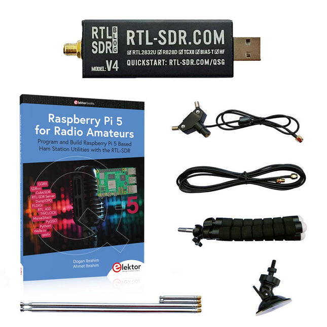
Elektor Bundles Raspberry Pi 5 RTL-SDR V4 (Bundle)
Program and build Raspberry Pi based ham station utilities, tools, and instruments The improved RTL-SDR V4 allows you to receive radio signals between 500 kHz and 1.75 GHz from stations utilizing different bands including MW/SW/LW broadcast, ham radio, utility, air traffic control, PMR, SRD, ISM, CB, weather satellite, and radio astronomy. The book Raspberry Pi 5 for Radio Amateurs gives extensive coverage of deploying the RTL-SDR kit through the use of a Raspberry Pi 5. This bundle contains: RTL-SDR V4 (incl. Dipole Antenna Kit) (normal price: €75) Raspberry Pi 5 for Radio Amateurs (normal price: €40) RTL-SDR V4 (Software Defined Radio) with Dipole Antenna Kit RTL-SDR is an affordable dongle that can be used as a computer-based radio scanner for receiving live radio signals between 500 kHz and 1.75 GHz in your area. The RTL-SDR V4 offers several improvements over generic brands including use of the R828D tuner chip, triplexed input filter, notch filter, improved component tolerances, a 1 PPM temperature compensated oscillator (TCXO), SMA F connector, aluminium case with passive cooling, bias tee circuit, improved power supply, and a built in HF upconverter. RTL-SDR V4 comes with the portable dipole antenna kit. It is great for beginners as it allows for terrestrial and satellite reception and easy to mount outdoors and designed for portable and temporary outside usage. Features Improved HF reception: V4 now uses a built-in upconverter instead of using a direct sampling circuit. This means no more Nyquist folding of signals around 14.4 MHz, improved sensitivity, and adjustable gain on HF. Like the V3, the lower tuning range remains at 500 kHz and very strong reception may still require front end attenuation/filtering. Improved filtering: The V4 makes use of the R828D tuner chip, which has three inputs. The SMA input has been triplexed input into 3 bands: HF, VHF and UHF. This provides some isolation between the 3 bands, meaning out of band interference from strong broadcast stations is less likely to cause desensitization or imaging. Improved filtering x2: In addition to the triplexing, the open drain pin on the R828D can be also used, which allows to add simple notch filters for common interference bands such as broadcast AM, broadcast FM and the DAB bands. These only attenuate by a few dB, but may still help. Improved phase noise on strong signals: Due to an improved power supply design, phase noise from power supply noise has been significantly reduced. Less heat: Another advantage of the improved power supply is low power consumption and less heat generation compared to the V3. Included 1x RTL-SDR V4 dongle (R828D RTL2832U 1PPM TCXO SMA) 2x 23 cm to 1 m telescopic antenna 2x 5 cm to 13 cm telescopic antenna 1x Dipole antenna base with 60 cm RG174 1x 3 m RG174 extension cable 1x Flexible tripod mount 1x Suction cup mount Downloads Datasheet User Guide Quick Start Guide SDR# User Guide Dipole Antenna Guide Book: Raspberry Pi 5 for Radio Amateurs The RTL-SDR devices (V3 and V4) have gained popularity among radio amateurs because of their very low cost and rich features. A basic system may consist of a USB based RTL-SDR device (dongle) with a suitable antenna, a Raspberry Pi 5 computer, a USB based external audio input-output adapter, and software installed on the Raspberry Pi 5 computer. With such a modest setup, it is possible to receive signals from around 24 MHz to over 1.7 GHz. This book is aimed at amateur radio enthusiasts and electronic engineering students, as well as at anyone interested in learning to use the Raspberry Pi 5 to build electronic projects. The book is suitable for both beginners through experienced readers. Some knowledge of the Python programming language is required to understand and eventually modify the projects given in the book. A block diagram, a circuit diagram, and a complete Python program listing is given for each project, alongside a comprehensive description. The following popular RTL-SDR programs are discussed in detail, aided by step-by-step installation guides for practical use on a Raspberry Pi 5: SimpleFM GQRX SDR++ CubicSDR RTL-SDR Server Dump1090 FLDIGI Quick RTL_433 aldo xcwcp GPredict TWCLOCK CQRLOG klog Morse2Ascii PyQSO Welle.io Ham Clock CHIRP xastir qsstv flrig XyGrib FreeDV Qtel (EchoLink) XDX (DX-Cluster) WSJT-X The application of the Python programming language on the latest Raspberry Pi 5 platform precludes the use of the programs in the book from working on older versions of Raspberry Pi computers.
-
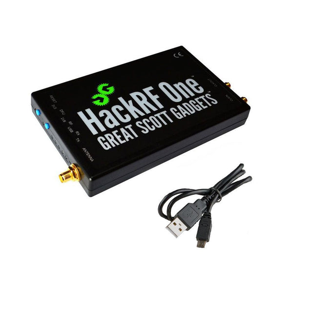
Great Scott Gadgets Great Scott Gadgets HackRF One SDR (1 MHz – 6 GHz)
New Version available! Click here! HackRF One is a Software Defined Radio (SDR) peripheral capable of transmission or reception of radio signals from 1 MHz to 6 GHz. Designed to enable test and development of modern and next generation radio technologies, HackRF One is an open source hardware platform that can be used as a USB peripheral or programmed for stand-alone operation. Specifications 1 MHz to 6 GHz operating frequency Half-duplex transceiver Up to 20 million samples per second 8-bit quadrature samples (8-bit I and 8-bit Q) Compatible with GNU Radio, SDR and more Software-configurable RX and TX gain and baseband filter Software-controlled antenna port power (50 mA at 3.3 V) SMA female antenna connector SMA female clock input and output for synchronization Convenient buttons for programming Internal pin headers for expansion Hi-Speed USB 2.0 USB-powered Open source hardware HackRF One is test equipment for RF systems. It has not been tested for compliance with regulations governing transmission of radio signals. You are responsible for using your HackRF One legally. Included 1x HackRF One SDR 1x Plastic enclosure 1x micro-USB cable Note: An antenna is not included. ANT500 is recommended as a starter antenna for HackRF One. Downloads Documentation GitHub Source code and hardware design files


