
Search results for "pi or supply or micro or bit or tinker or kit or micro or bit or included"
-

Elektor Digital Raspberry Pi Pico W en un tournemain (PDF)
Maîtrise de la puce RP2040 avec plus de 60 projets à réaliser et à programmer Les cartes Raspberry Pi Pico et Pico W sont animées par un microcontrôleur ARM Cortex M0+ RP2040 à double coeur, rapide, efficace et peu coûteux, qui fonctionne jusqu'à 133 MHz et dispose de 264 Ko de SRAM et de 2 Mo de mémoire Flash. Outre une vaste mémoire, le Pico et le Pico W disposent de nombreuses broches GPIO et d'interfaces telles que CA/N, SPI, I²C, UART, MLI, de fonctions de temporisation, d'une interface de débogage matériel et d'un capteur de température interne. La carte Raspberry Pi Pico W comporte en plus une puce CYW43439 Bluetooth et Wi-Fi d'Infineon. Au moment de la rédaction de ce livre, le micrologiciel Bluetooth pour le Pico W n'était pas encore disponible. Le Wi-Fi à 2,4 GHz est toutefois entièrement pris en charge avec les protocoles 802.11b/g/n. Ce livre est une introduction à l'utilisation du Raspberry Pi Pico W avec le langage de programmation MicroPython. Les quelque soixante projets testés et opérationnels sont présentés à l'aide de l'environnement de développement intégré (EDI) Thonny. Les sujets abordés sont nombreux : Installation de MicroPython sur le Raspberry Pi Pico depuis un PC Interruptions de l'horloge et interruptions externes Convertisseur analogique-numérique (CA/N) Capteurs de température interne et externe Capteurs externes (pression, humidité, pouls, à ultrasons) Enregistrement de données MLI, UART, I²C et SPI Bluetooth, Wi-Fi et applis sur smarphone Convertisseur numérique-analogique (CN/A) Tous les projets ont été testés et éprouvés. Ils peuvent être mis en oeuvre sur le Raspberry Pi Pico ainsi que sur le Raspberry Pi Pico W. Toutefois les projets avec une liaison Wi-Fi ne fonctionnent que sur le Pico W. Une petite expérience en programmation et en électronique est nécessaire pour suivre les projets. De brèves descriptions, des schémas fonctionnels, des schémas détaillés du câblage des montages et des listings MicroPython complets sont fournis pour tous les projets.
€ 34,95
Members: € 31,46
-

Elektor Bundles 555 Timer Projects (Bundle)
This bundle is all about designing projects based on the 555 timer IC. The book features over 45 fully tested and documented projects. Together with the kit, which contains more than 130 through-hole components, you can build all the projects described on a breadboard. The setup also makes it easy to modify and experiment with the projects. Over 45 Builds for the Legendary 555 Chip (and the 556, 558) Some of the projects in the book are: Alternately Flashing Two LEDs Changing LED Flashing Rate Touch Sensor On/Off Switch Switch On/Off Delay Light-Dependent Sound Dark/Light Switch Tone Burst Generator Long Duration Timer Chasing LEDs LED Roulette Game Traffic Lights Continuity Tester Electronic Lock Switch Contact Debouncing Toy Electronic Organ Multiple Sensor Alarm System Metronome Voltage Multipliers Electronic Dice 7-Segment Display Counter Motor Control 7-Segment Display Dice Electronic Siren Various Other Projects Kit Contents Resistors 1x 15 kΩ 1x 68 kΩ 2x 47 kΩ 1x 82 kΩ 2x 820 Ω 1x 8.2 kΩ 3x 10 kΩ 1x 1.8 kΩ 1x 6.8 kΩ 14x 2.2 kΩ 10x 680 Ω 1x 27 kΩ 1x 5.6 kΩ 1x 560 kΩ 1x 4.7 kΩ 1x 3.3 kΩ 3x 33 kΩ 1x 36 kΩ 2x 100 kΩ 5x 1 kΩ 1x 3.9 kΩ 2x 56 kΩ 2x 12 kΩ 1x 10 kΩ potentiometer 1x 1 MΩ potentiometer 2x 50 kΩ potentiometer 3x 20 kΩ potentiometer 1x 10 kΩ potentiometer 1x 10 kΩ potentiometer 1x 50 kΩ potentiometer 1x 100 kΩ potentiometer 1x 50 kΩ potentiometer Capacitors 1x 0.33 μF 1x 1 μF 1x 10 nF 1x 22 nF 1x 47 nF 1x 100 nF 1x 10 μF electrolytic 1x 33 μF electrolytic 2x 100 μF electrolytic LEDs 10x 5 mm red LED 10x 3 mm red LED 3x 3 mm yellow LED 3x 3 mm green LED 1x Common-cathode 7-segment LED Semiconductors 3x 555 timer 1x CD4017 counter 1x CD4026 counter 1x CD4011 NAND gate 4x 1N4148 diode 1x IRFZ46N MOSFET 1x Thermistor 1x Light dependent resistor (LDR) Miscellaneous 1x Passive buzzer 1x Active buzzer 1x SG90 servo 1x 8 Ω mini loudspeaker 1x 9 V DC brushed motor 1x 5 V relay 1x 9 V battery clip 7x Pushbutton switches 1x Breadboard 1x Breadboard jumper wires
€ 69,95€ 54,95Best Price
-
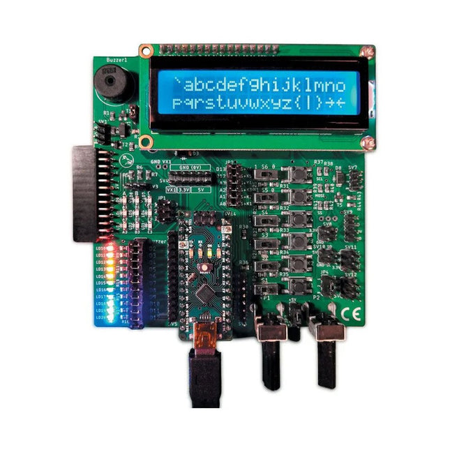
Elektor Labs Elektor Arduino Nano MCCAB Training Board
The Elektor Arduino Nano MCCAB Training Board contains all the components (incl. Arduino Nano) required for the exercises in the "Microcontrollers Hands-on Course for Arduino Starters", such as light-emitting diodes, switches, pushbuttons, acoustic signal transmitters, etc. External sensors, motors or assemblies can also be queried or controlled with this microcontroller training system. Specifications (Arduino Nano MCCAB Training Board) Power Supply Via the USB connection of the connected PC or an external power supply unit (not included) Operating Voltage +5 Vcc Input Voltage All inputs 0 V to +5 V VX1 and VX2 +8 V to +12 V (only when using an external power supply) Hardware periphery LCD 2x16 characters Potentiometer P1 & P2 JP3: selection of operating voltage of P1 & P2 Distributor SV4: Distributor for the operating voltagesSV5, SV6: Distributor for the inputs/outputs of the microcontroller Switches and buttons RESET button on the Arduino Nano module 6x pushbutton switches K1 ... K6 6x slide switches S1 ... S6 JP2: Connection of the switches with the inputs of the microcontroller Buzzer Piezo buzzer Buzzer1 with jumper on JP6 Indicator lights 11 x LED: Status indicator for the inputs/outputs LED L on the Arduino Nano module, connected to GPIO D13 JP6: Connection of LEDs LD10 ... LD20 with GPIOs D2 ... D12 Serial interfacesSPI & I²C JP4: Selection of the signal at pin X of the SPI connector SV12 SV9 to SV12: SPI interface (3.3 V/5 V) or I²C interface Switching output for external devices SV1, SV7: Switching output (maximum +24 V/160 mA, externally supplied) SV2: 2x13 pins for connection of external modules 3x3 LED matrix(9 red LEDs) SV3: Columns of the 3x3 LED matrix (outputs D6 ... D8) JP1: Connection of the rows with the GPIOs D3 ... D5 Software Library MCCABLib Control of hardware components (switches, buttons, LEDs, 3x3 LED matrix, buzzer) on the MCCAB Training Board Operating Temperature Up to +40 °C Dimensions 100 x 100 x 20 mm Specifications (Arduino Nano) Microcontroller ATmega328P Architecture AVR Operating Voltage 5 V Flash Memory 32 KB, of which 2 KB used by bootloader SRAM 2 KB Clock Speed 16 MHz Analog IN Pins 8 EEPROM 1 KB DC Current per I/O Pins 40 mA on one I/O pin, total maximum 200 mA on all pins together Input Voltage 7-12 V Digital I/O Pins 22 (6 of which are PWM) PWM Output 6 Power Consumption 19 mA Dimensions 18 x 45 mm Weight 7 g Included 1x Elektor Arduino Nano Training Board MCCAB 1x Arduino Nano
€ 79,95€ 69,95Best Price
-
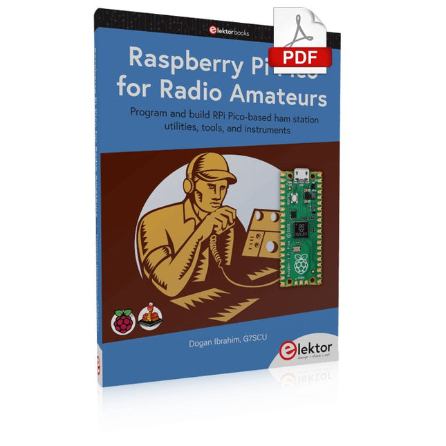
Elektor Digital Raspberry Pi Pico for Radio Amateurs (E-book)
Program and build RPi Pico-based ham station utilities, tools, and instruments Although much classical HF and mobile equipment is still in use by large numbers of amateurs, the use of computers and digital techniques has now become very popular among amateur radio operators. Nowadays, anyone can purchase a €5 Raspberry Pi Pico microcontroller board and develop many amateur radio projects using the “Pico” and some external components. This book is aimed at amateur radio enthusiasts, Electronic Engineering students, and anyone interested in learning to use the Raspberry Pi Pico to shape their electronic projects. The book is suitable for beginners in electronics as well as for those with wide experience. Step-by-step installation of the MicroPython programming environment is described. Some knowledge of the Python programming language is helpful to be able to comprehend and modify the projects given in the book. The book introduces the Raspberry Pi Pico and gives examples of many general-purpose, software-only projects that familiarize the reader with the Python programming language. In addition to the software-only projects tailored to the amateur radio operator, Chapter 6 in particular presents over 36 hardware-based projects for “hams”, including: Station mains power on/off control Radio station clock GPS based station geographical coordinates Radio station temperature and humidity Various waveform generation methods using software and hardware (DDS) Frequency counter Voltmeter / ammeter / ohmmeter / capacitance meter RF meter and RF attenuators Morse code exercisers RadioStation Click board Raspberry Pi Pico based FM radio Using Bluetooth and Wi-Fi with Raspberry Pi Pico Radio station security with RFID Audio amplifier module with rotary encoder volume control Morse decoder Using the FS1000A TX-RX modules to communicate with Arduino
€ 32,95
Members: € 29,66
-

Elektor Digital Das offizielle Raspberry Pi Handbuch (PDF)
Von den Machern von MagPi, dem offiziellen Raspberry Pi Magazin Starten Sie jetzt mit dem Raspberry Pi 5, dem neuesten und besten Minicomputer von Raspberry Pi – und lernen Sie, mit diesem unglaublichen Computer zu programmieren und Projekte zu erstellen. In diesem Buch finden Sie außerdem jede Menge kreative Ideen und Tipps, die Sie mit dem Raspberry Pi 4, dem Raspberry Pi Zero 2 W und dem Raspberry Pi Pico W umsetzen können. Mit den neuesten Reviews, Tutorials, Projekten, Anleitungen und mehr ist dies Ihre ultimative Ressource für den Raspberry Pi! 228 Seiten über Raspberry Pi Alles, was Sie über den Raspberry Pi 5 wissen müssen Erste Schritte für jeden Raspberry Pi Viel Spaß mit Elektronik und dem Pico W Inspirierende Projekte für Ihre nächste Bauidee Lernen Sie MicroPython, indem Sie ein Handheld bauen Erste Schritte mit dem Raspberry Pi Camera Modul Künstliche Intelligenz: Bauen Sie Ihren eigenen GPT Chatbot
€ 29,80
Members: € 26,82
-

Elektor 09-10/2026 (DE)
Diese Ausgabe steht allen GOLD- und GREEN-Mitgliedern auf der ElektorMagazine-Website zum Download bereit! Sie sind noch kein Mitglied? Hier klicken! Der ESP-BLASTEine Mini-Raketendrohne mit ESP32, die über 100 km/h erreicht Wireless Workshop (1)Freigeschaltetes Funkmodul: 433-MHz-CC1101-Sub-GHz-Transceiver AM-Sendermit Rechteck-/Sinuswellengenerator auf Raspberry Pi Pico STM32Cube Innovations ChallengeTreten Sie mit Ihrem besten STM32C5-Design an CoffeeCallerWie ein langer Flur zu einer maßgefertigten Mesh-Netzwerk-Platine führte AudiotronicsKlirrfaktor Elektor ist 65Projekte aus früheren September/Oktober-Ausgaben Geräteortung durch Bluetooth Channel SoundingZentimetergenaue Entfernungsmessung im IoT der nächsten Generation 2026: Eine KI-OdysseeQuantencomputing ist nicht die nächste GPU Cloud-Schutz durch Edge-Sicherheit Erste Erfahrungen mit dem HackRF ProPraktische Tests mit der neuen SDR-Hardware Herausforderung ElektromobilitätEffiziente Lötlösungen für moderne Fahrzeugtechnik Modem-Update von GPRS/2G auf LTE/4Gam Beispiel einer Funk-Alarmzentrale Loop-Antenne mit RF BricksTeil 1: Kurzwellen-Antenne mit einstellbarer Richtwirkung im Selbstbau Internetradio-zu-AM-KonverterVerwendung eines ESP32-S3 als Sender Projekt 2.0 mioty – ein ÜberblickLPWAN à la Fraunhofer Werkbank-WeisheitPraktische Tipps von Experten Walter, das kompakte IoT-ModulTeil 2: Zugriff auf Wetter- und Datendienste
€ 15,90
-
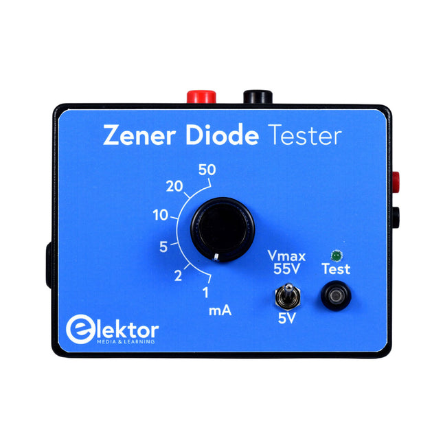
Elektor Zener Diode Tester
The Elektor Zener Diode Tester is essentially a constant-current source that can be switched in steps from 1 to 50 mA. It can be used to test Z-diodes up to a maximum of 54 V. Thanks to a 60-V step-up converter, the device can be powered by the usual 5 to 12 V. The principle of this tester is straightforward. A Z-diode or other DUT (device under test, such as an LED) is biased by an adjustable current source. The voltage across the DUT can be measured with a multimeter. The voltage of most (small) Z-diodes is specified at a current of 5 mA. Depending on the application, the voltage at other currents can also be of interest. That is why six current settings are available: 1, 2, 5, 10, 20, and 50 mA. LEDs are often specified at a current of 20 mA. What can be tested is: Whether a Z-diode is defective (short circuit or high impedance). Whether a Z-diode exhibits the correct Z-voltage. How a Z-voltage changes with different currents. What exact voltage is present at an integrated voltage reference. Whether LEDs in a series chain differ in brightness (hence the 20 mA current). What the current gain is for different base currents in (power) transistors. The kit contains all parts listed in the bill of materials including PCB and enclosure. Specifications Supply voltage 5…12 V/2 A (USB-C) Supply current (Itest = 50 mA) 1.1 A @ 5 V / 412 mA @ 12 V Selectable currents 1, 2, 5, 10, 20, and 50 mA Max. test voltage >54 V @ Itest ≥1 mA Max. output voltage 60 V @ Itest = 0 mA Voltage limit at 5 V 4.5 V @ Itest = 1 mA / 5.18 V @ Itest = 50 mA Enclosure dimensions 110 x 82 x 44 mm PCB size 105.4 x 67.3 mm Connections 4 mm banana sockets for multimeter 2 mm banana sockets for test clips USB-C socket for power supply Included Resistors R1 = 3.3 kΩ, 600 mW, 1% R2 = 0.15 Ω, 1 W, 5%, LS 12.7 mm, ø 3.5 mm R3, R8 = 180 Ω, 600 mW, 1% R4, R6, R16 = 1 kΩ, 600 mW, 1% R5, R19 = 47 kΩ, 600 mW, 1% R7 = 3.9 kΩ, 1 W, 5%, LS 12.7 mm, ø 3.5 mm R9, R10, R12 = 10 kΩ, 600 mW, 1% R11, R13 = 100 Ω, 600 mW 1% R14 = 249 Ω, 600 mW, 1% R15 = 499 Ω, 600 mW, 1% R17 = 2.49 kΩ, 250 mW, 1% R18 = 4.99 kΩ, 250 mW, 1% Capacitors C1 = 470 uF / 35 V, 20%, Ir = 1.86 A, ø 12.5 mm, LS 5 mm, ESR = 0.038 Ω (Panasonic EEUTP1V471) C2 = 1 uF / 100 V, 10%, X7R, LS 5 mm C3 = 2.2 nF / 50 V, 10%, X7R, LS 5 mm C4, C7 = 100 nF / 100 V, 10%, X7R, LS 5 mm C5 = 100 uF / 100 V, 20%, ø 14 mm max., LS 5 mm C6 = 1 nF / 100 V, 10%, X7R, LS 5 mm Inductor L1 = 100 uH, Irms = 2.4 A, Isat = 3.5 A, 0.09 Ω, radial, pitch 2.5/5/10 mm, ø 14 mm max. (Kemet SBC8-101-242) Semiconductors D1 = MUR120G, DO-41 D2, D4 = STPS3150RL, DO-201AD D3 = Z-diode, 18 V, 1.3 W (BZX85C18) D5 = Z-diode, 5.1 V, 0.5 W (1N5231B) LED1 = LED in pushbutton S1 LED2 = LED, green, 3 mm IC1 = MC34063, DIP-8 IC2 = LM4040BIZ-5.0/NOPB, TO-92 (TO-226AA-3) IC3 = TL051CP, DIP-8 T1 = BC327.25, TO-92 T2 = STP40NF10L, TO-220 T3 = IRF9510PBF, TO-220 T4 = 2N7000, TO-92 Others K1, K2, S1, S3 = 2-way screw terminal block, LS 3.5 mm, max. 1.5 mm² connected to K1 = USB-C socket, 30 V/3 A, chassis mounted, wired, 9 x 16 mm connected to K2 = Banana Connector, 2 mm, Socket, 60 VDC, Panel Mount, red (Multicomp 24.102.1) connected to K2 = Banana Connector, 2 mm, Socket, 60 VDC, Panel Mount, black (Multicomp 24.102.2) Test clip, red, 30 VAC/60 VDC (Hirschmann 931467101) Test clip, black, 30 VAC/60 VDC (Hirschmann 931467100) S1 = Pushbutton, panel mount, SPST-NO, 30 DC/100 mA, with red LED S2 = Rotary Switch, 6 position, 2 pole, 30°, 250 V/150 mA S3 = Toggle switch, panel mount, SPDT, solder lugs, 28 VDC T2, T3 = Heat sink, 15°C/W, FK 214 SA-CB Enclosure Hammond 1591XXSSBK, ABS, 110 x 82 x 44 mm Knob for S2, round shaft 6 mm, ø 21 mm, with indicator line (Multicomp CP-LB21-6-6D) 4 x Self-tapping screw #4-1/4", carbon steel, pan head Banana plug, red, 2 mm, 60 VDC (Multicomp 25.205.1) Banana plug, black, 2 mm, 60 VDC (Multicomp 25.205.2) Banana socket, black 4 mm, panel mount Banana socket, red 4 mm, panel mount for LED1, LED2 = Pin header, 1 x 2, vertical, pitch 2.54 mm for LED1, LED2 = Pin socket, 1 x 2, vertical, pitch 2.54 mm for T2, T3 = M3 screw, 10 mm, steel, pan head 2 x M3 washer, plain, steel 4 x M3 nut for IC1, IC3 = DIP-8 socket Wire, black, 0.25 mm² (24 AWG), stranded 14 x 0.15 mm, 1 m Wire, red, 0.25 mm² (24 AWG), stranded 14 x 0.15 mm, 1 m PCB 250772-1 v1.1 Links Article Elektor Labs
€ 99,95€ 79,95Best Price
-
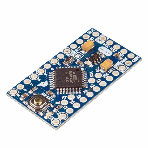
SparkFun SparkFun Arduino Pro Mini 328 (5 V, 16 MHz)
The Arduino Pro Mini is a microcontroller board based on the ATmega328P. It has 14 digital input/output pins (of which 6 can be used as PWM outputs), 6 analog inputs, an on-board resonator, a reset button, and holes for mounting pin headers. A six pin header can be connected to an FTDI cable or SparkFun breakout board to provide USB power and communication to the board. The Arduino Pro Mini is intended for semi-permanent installation in objects or exhibitions. The board comes without pre-mounted headers, allowing the use of various types of connectors or direct soldering of wires. The pin layout is compatible with the Arduino Mini. The Arduino Pro Mini was designed and is manufactured by SparkFun Electronics. Specifications Microcontroller ATmega328P Board Power Supply 5-12 V Circuit Operating Voltage 5 V Digital I/O Pins 14 PWM Pins 6 UART 1 SPI 1 I²C 1 Analog Input Pins 6 External Interrupts 2 DC Current per I/O Pin 40 mA Flash Memory 32 KB of which 2 KB used by bootloader SRAM 2 KB EEPROM 1 KB Clock Speed 16 MHz Dimensions 18 x 33.3 mm (0.7 x 1.3") Downloads Eagle files Schematics
€ 14,95€ 7,95Best Price
-

Elektor Bundles Schnelleinstieg in die Elektronik (Bundle)
Der Einstieg in die Elektronik ist einfacher, als Sie denken! Mit diesem Bundle – bestehend aus Buch und Experimentierkit – entdecken Sie die Grundlagen der Elektro- und Elektroniktechnik Schritt für Schritt. Anhand spannender Experimente lernen Sie praxisnah und verständlich, ganz ohne komplizierte Fachbegriffe oder langwierige Berechnungen. So sind Sie schon bald in der Lage, Ihre eigenen Elektronikprojekte umzusetzen! Das Kit enthält alle notwendigen Komponenten, um die meisten im Buch beschriebenen Schaltungen direkt auf dem Steckbrett aufzubauen und praktisch zu erproben. Das Kit kann selbstverständlich auch ohne das Buch zum Aufbau anderer Schaltkreise und zur Durchführung eigener Experimente verwendet werden. Inhalt des Kits 1x 39 Ω, 1 W Widerstand 1x 47 Ω Widerstand 1x 180 Ω Widerstand 1x 330 Ω Widerstand 3x 1 kΩ Widerstand 1x 2,2 kΩ Widerstand 1x 3,9 kΩ Widerstand 1x 6,8 kΩ Widerstand 1x 10 kΩ Widerstand 1x 15 kΩ Widerstand 1x 22 kΩ Widerstand 1x 33 kΩ Widerstand 1x 47 kΩ Widerstand 1x 56 kΩ Widerstand 1x 82 kΩ Widerstand 1x 120 kΩ Widerstand 1x 680 kΩ Widerstand 2x 100 kΩ Widerstand 1x 10 kΩ Trimmer 1x 10 kΩ Linearpotentiometer 1x 100 kΩ Linearpotentiometer 1x LDR 1x 1 nF Keramikkondensator 2x 10 nF Keramikkondensator 1x 100 nF Keramikkondensator 1x 1 µF, 25 V Aluminium-Elektrolytkondensator 2x 10 µF, 25 V Aluminium-Elektrolytkondensator 1x 100 µF, 25 V Aluminium-Elektrolytkondensator 1x 470 µF, 25 V Aluminium-Elektrolytkondensator 1x 1000 µF, 25 V Aluminium-Elektrolytkondensator 1x RGB-LED, Common-Cathode (CC) 1x 1N4148 Kleinsignaldiode 1x 1N4733A 5,1 V, 1 W Zenerdiode 3x LED, rot 2x BC337 NPN-Transistor 1x IRFZ44N N-Kanal-MOSFET 2x NE555-Timer 1x LM393-Komparator 1x 74HCT08 Quad-AND-Gatter 3x Tastschalter 2x SPDT-Schalter 1x Relais, SPDT, 9 VDC 1x Aktiver Summer 1x Passiver Summer 50 cm Massivdraht, 16 AWG, ohne Mantel 2x PP3 9 V Batterieclip 1x Steckbrett 20x Überbrückungskabel Dieses Bundle enthält: Buch: Schnelleinstieg in die Elektronik (Einzelpreis: 45 €) Kit: Schnelleinstieg in die Elektronik (Wert: 45 €)
€ 89,95€ 69,95Best Price
-
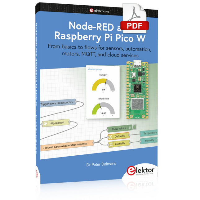
Elektor Digital Node-RED and Raspberry Pi Pico W (E-book)
From basics to flows for sensors, automation, motors, MQTT, and cloud services This book is a learning guide and a reference. Use it to learn Node-RED, Raspberry Pi Pico W, and MicroPython, and add these state-of-the-art tools to your technology toolkit. It will introduce you to virtual machines, Docker, and MySQL in support of IoT projects based on Node-RED and the Raspberry Pi Pico W. This book combines several elements into a platform that powers the development of modern Internet of Things applications. These elements are a flow-based server, a WiFi-enabled microcontroller, a high-level programming language, and a deployment technology. Combining these elements gives you the tools you need to create automation systems at any scale. From home automation to industrial automation, this book will help you get started. Node-RED is an open-source flow-based development tool that makes it easy to wire together devices, APIs, and online services. Drag and drop nodes to create a flowchart that turns on your lights at sunset or sends you an email when a sensor detects movement. Raspberry Pi Pico W is a version of the Raspberry Pi Pico with added 802.11n Wi-Fi capability. It is an ideal device for physical computing tasks and an excellent match to the Node-RED. Quick book facts Project-based learning approach. Assumes no prior knowledge of flow-based programming tools. Learn to use essential infrastructure tools in your projects, such as virtual machines, Docker, MySQL and useful web APIs such as Google Sheets and OpenWeatherMap. Dozens of mini-projects supported by photographs, wiring schematics, and source code. Get these from the book GitHub repository. Step-by-step instructions on everything. All experiments are based on the Raspberry Pi Pico W. A Wi-Fi network is required for all projects. Hardware (including the Raspberry Pi Pico W) is available as a kit. Downloads GitHub
€ 39,95
Members: € 35,96
-

Elektor Digital Het officiële Raspberry Pi Handboek (PDF)
Van de makers van MagPi, het officiële Raspberry Pi-magazine Ga aan de slag met Raspberry Pi 5, de nieuwste en beste in de Raspberry Pi-microcomputerlijn; leer programmeren en creeren met deze fantastische computer. Daarnaast zijn er nog genoeg dingen die je kunt doen met Raspberry Pi 4, Raspberry Pi Zero 2 W en Raspberry Pi Pico W in dit handboek. Met de nieuwste recensies, tutorials, projectpresentaties, handleidingen en nog veel meer is dit je ultieme bron voor Raspberry Pi! 228 pagina’s Raspberry Pi Alles wat je moet weten over de Raspberry Pi 5 Snelle en praktische gids voor elke Raspberry Pi Beleef serieus plezier met elektronica en de Pico W Inspirerende projecten voor uw volgende bouwidee Leer μPython door een “handheld” te bouwen Aan de slag met de Raspberry Pi Camera-module Kunstmatige Intelligentie; bouw je eigen GPT Chatbot
€ 29,95
Members: € 26,96
-

Elektor Digital Piccolino - 30 Projects, mods, hacks and extension (E-book)
The Piccolino rapid development board can be used to design microcontroller circuits quickly. The Piccolino has a fast 16f887 PIC microcontroller, voltage regulator, and communications module, and can be easily extended using its four headers. This e-book contains 30 projects based on the Piccolino. We'll use its unique communications facilities and get the Piccolino to communicate with programs on a PC. On the PC, we use the free programming language Small Basic. You can use this to create Windows programs with buttons and graphs quickly. You will learn how to analyze components such as inductors, capacitors, and OPAMPs, and how to display the measurement results in a graphical format. This will help you to design your circuits easily. We will then start to adapt to the Piccolino. We'll add components to it to make it more powerful, with extra features such as flow control and digital to analog conversion. The clear instructions will enable you to design and build your adaptations. This way you can make your custom designed Piccolino. We'll end up making an extension: a PCB that that can be mounted on the Piccolino headers. As an example, we'll design and build an extension for an LCD. You can use the included board layout to make your PCB or have it made for you. At the same time, you will learn how to make your extensions. The only limitation is your imagination! The clear descriptions along with circuit diagrams and photos, will make the building of these projects an enjoyable experience. Each project has a clear explanation of the reasons why it was designed in a particular way. This helps you learn a lot about the Piccolino, as well as Small Basic, and the components that are used in this e-book. You can adapt the projects to suit your requirements or combine several projects.
€ 34,95
Members: € 31,46


