Drahtlose Kommunikation – sei es zur Ton-, Daten- oder Bildübertragung – prägt unser heutiges Leben. Während noch Mitte des letzten Jahrhunderts der Rundfunk (und etwas später das Fernsehen) die dominierenden Anwendungen der drahtlosen Kommunikation waren, gibt es heute kaum mehr ein technisches Gerät, das nicht das Mittel der drahtlosen Kommunikation nutzt. Allen voran das beliebte Smartphone.
Daneben gibt es sehr viele Anwendungen, die wir nicht sofort und automatisch mit den Begriffen Radio oder Funk verbinden, die aber auf der Nutzung elektromagnetischer Strahlung basieren. So zum Beispiel der Wagenschlüssel, die über Bluetooth verbundenen Kopfhörer, der automatische Rasenmäher, die gehassten Radargeschwindigkeitsmesser, der Laptop, der über Wi-Fi mit dem Internet verbunden ist, die kleinen Navigationsempfänger, usw.
Diesen Anwendungen gemeinsam ist die Nutzung physikalischer Gegebenheiten durch die Technik. Ob Radar, Satellitenfernsehen, oder einfach nur das alte Mittelwellenradio, alle bauen auf denselben Grundlagen auf.
Das Ziel dieses Buch ist es, diese Grundlagen zu erläutern und damit das Verständnis für die darauf aufbauenden Anwendungen zu fördern. Es soll Studenten den Einstieg ins Fachgebiet erleichtern und Voraussetzungen für den Zugang zu den Standardwerken der Fachliteratur schaffen. Es richtet sich aber auch an Personen, die an der Physik und der Technik interessiert sind und einen tieferen Einblick in die Grundlagen der drahtlosen Kommunikation und deren Anwendung erhalten wollen.
A Toolbox for Audio Lovers and Engineers
Without any ambition to reach scientific levels, this book aims to be a toolbox for both audio lovers and high-end equipment designers. The elementary theory presented is the bare minimum for readers to grasp the operation and practical use of electrical, electromagnetic, physics, and electronic operations available in the designers’ toolbox. Each tool is explained in a minimum of words and theory without needless coverage of underlying equations or figures.
The book chapters guide you through the process of designing quality amplifiers with vacuum tubes, from the very beginning, considering both technical and subjective requirements – in theory and practice.
The book is a compilation of the author’s notes used in his professional and educational career but was nevertheless primarily written as a result of true love for the audiophile hobby.
Ungefähr seit dem Jahr 2000 bieten Fahrzeuge Zugriff auf Diagnosedaten, Messwerte und erkannte Fehler, die mit preiswerten Geräten ausgelesen werden können. Die Daten helfen Ihnen nicht nur bei der Fehlersuche, sondern auch beim Gebrauchtwagenkauf oder dem reibungslosen Bestehen der nächsten Hauptuntersuchung. Die zunehmende Komplexität und Vernetzung der integrierten elektronischen Kontroll- und Steuerungssysteme im Fahrzeug erfordert vom Kfz-Mechatroniker sowie dem ambitionierten Selbstschrauber ein tiefgreifendes Verständnis der Thematik.
Dieses Sachbuch bietet Ihnen eine umfassende Einführung zu den in Kraftfahrzeugen vorhandenen genormten On-Board-Diagnosemöglichkeiten (OBD II), deren Ursprünge, Stand der Entwicklung, Protokollaufbau und Anwendung. Das Buch richtet sich an eine breite Leserschaft, die selbst die Möglichkeiten nutzen will, um nicht mehr auf kostspielige Werkstattbesuche angewiesen zu sein oder sich für eine Eigenentwicklung von Diagnosesystemen und eine praxisnahe Beschreibung der Protokolle interessiert.
Durch den Einsatz günstiger Diagnoseadapter (ELM 327 etc.) können Sie sich auf dem Smartphone Live-Daten anzeigen lassen und Cockpitinstrumente nachrüsten oder eigene Anwendungssoftware für verschiedene Systeme erstellen.
Themenauswahl
Historische Entwicklung der Diagnosemöglichkeiten und Standards
Funktionsumfang von OBD II mit allen zehn Diagnosemodi und Readinesscode
World Wide Harmonized OBD (WWH-OBD) und HD OBD (Heavy Duty: Nutzfahrzeuge)
Anschlüsse gemäß SAE J1962, SAE J1939, SAE J1708 und DoIP (ISO 13400)
Protokollaufbau nach SAE J1850, ISO 9141, ISO 14230 und CAN
Übersicht gängiger Diagnoselösungen für Hobbyanwender
Eigenbau von Diagnosesystemen mit Arduino und Raspberry Pi
Alle Parameter Identifier (Messwerte) für OBD II
Umfangreiche Liste der Fehlercodes zum Nachschlagen
Bent u altijd al op zoek geweest naar een handig naslagwerk op het gebied van elektrotechniek en elektronica? Een boek waarin alles te vinden is wat in de dagelijkse praktijk voor hobby, studie of werk nodig is? Dan hoeft u niet langer verder te zoeken. U heeft namelijk gevonden wat u zoekt: Compendium Elektrotechniek (en elektronica). Met dit boek haalt u een grote diversiteit aan praktische kennis in huis. Alles wat u ooit beheerst heeft en waarvan u weet dat het ergens te vinden moet zijn, is nu terug te vinden in één boekwerk!
Compendium Elektrotechniek is samengesteld door studenten en docenten van de Universiteit Twente. In het boek komen zowel theorie als praktijk aan bod. In het theoretische deel komen wiskunde, informatica, fysica, meettechniek, signaal- en systeemtheorie en elektronica aan de orde. Het praktische deel is onderverdeeld in de hoofdstukken componenten, audio/video en voedingen. Het is een verzameling informatie die regelmatig van pas komt voor iedereen die met elektrotechniek te maken heeft. Van pinouts van stekkers en IC's tot kleurcodes van weerstanden en schema's van spanningsregelaars.
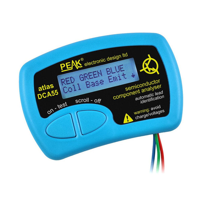
The Peak Atlas DCA55 is great for automatically identifying the type of semiconductor on the test leads as well as the pinout and many other parameters.
Supports transistors MOSFETs, JFETs (gate pin only can be identified), diodes, LEDs and lots more. Automatically identifies type of component, pinout and other important parameters. Now features transistor leakage measurement and Germanium/Silicon identification.
Component Support
Bipolar transistors (NPN/PNP inc Silicon/Germanium)
Darlington transistors (NPN/PNP)
Enhancement mode MOSFETs (N-Ch and P-Ch)
Depletion mode MOSFETs (N-Ch and P-Ch)
Junction FETs (N-Ch and P-Ch). Only gate lead identified
Diodes and diode networks (2 and 3 lead types)
LEDs and bi-colour LEDs (2 lead and 3 lead types)
Low power sensitive Triacs and Thyristors (<5 mA trigger and hold)
Measurements
Part type identification
Pinout identification
BJT current gain (hFE)
BJT base emitter voltage (Vbe)
BJT collector leakage current
MOSFET gate threshold voltage
Diode forward voltage drop (Vf)
Specifications
Analyzer type
Transistors, Diodes, LEDs, MOSFETs, JFETs
Pinout detection
Full pinout (only Gate on JFETs)
Pinout configuration
Connect any way round
Transistor measurements
Vbe, hFE, Iceo
MOSFET measurements
Vgs(on)
Diode measurements
Vf
Probe type
Universal grabber type
Battery
Single AAA cell (supplied). Life typically 1300 ops
Test conditions
Typically 5 mA, 5 V peak
Display type
Alphanumeric LCD (with backlight)
Included
Peak Atlas DCA55 Semiconductor Analyzer
Comprehensive illustrated user guide
Fitted universal hook probes
AAA Alkaline battery
Downloads
Datasheet (EN)
User Guide (EN)
User Guide (IT)
Build your own AI microcontroller applications from scratch
The MAX78000FTHR from Maxim Integrated is a small development board based on the MAX78000 MCU. The main usage of this board is in artificial intelligence applications (AI) which generally require large amounts of processing power and memory. It marries an Arm Cortex-M4 processor with a floating-point unit (FPU), convolutional neural network (CNN) accelerator, and RISC-V core into a single device. It is designed for ultra-low power consumption, making it ideal for many portable AI-based applications.
This book is project-based and aims to teach the basic features of the MAX78000FTHR. It demonstrates how it can be used in various classical and AI-based projects. Each project is described in detail and complete program listings are provided. Readers should be able to use the projects as they are, or modify them to suit their applications. This book covers the following features of the MAX78000FTHR microcontroller development board:
Onboard LEDs and buttons
External LEDs and buttons
Using analog-to-digital converters
I²C projects
SPI projects
UART projects
External interrupts and timer interrupts
Using the onboard microphone
Using the onboard camera
Convolutional Neural Network
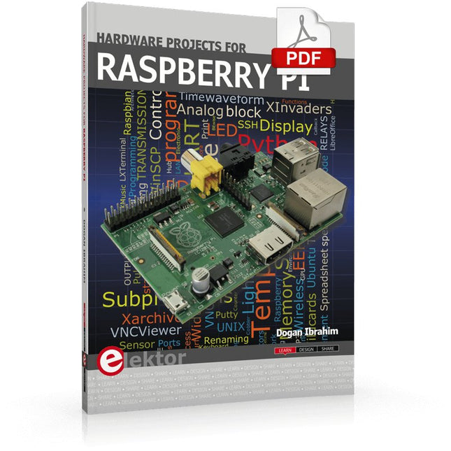
The Raspberry Pi is a $35 credit-card sized computer with many applications, such as in desktop computing, audio and video playback, and as a controller in many industrial, commercial and domestic applications.
This book is about the Raspberry Pi computer and its use in control applications. The book explains in simple terms, with examples, how to configure the RPi, how to install and use the Linux operating system, how to write programs using the Python programming language and how to develop hardware based projects.
The book starts with an introduction to the Raspberry Pi computer and covers the topics of purchasing all the necessary equipment and installing/using the Linux operating system in command mode. Use of the user-friendly graphical desktop operating environment is explained using example applications. The RPi network interface is explained in simple steps and demonstrates how the computer can be accessed remotely from a desktop or a laptop computer.
The remaining parts of the book cover the Python programming language, hardware development tools, hardware interface details, and RPi based hardware projects. All the 23 projects given in the book have been tested and are working.
The following headings are given for each project:
Project title
Project description
Project block diagram
Project circuit diagram
Project program description using the Program Description Language (PDL)
Complete program listing
Description of the program
The book is ideal for self-study, and is intended for electronic/electrical engineering students, practising engineers, research students, and hobbyists.
The OWON SDS1102 is an affordable benchtop digital oscilloscope that combines solid performance with essential measurement features. This 2-channel oscilloscope offers a 100 MHz bandwidth, a 1 GS/s sampling rate, a 7-inch LCD display, and a 10 kpts memory depth, making it a practical choice for everyday electronics testing, troubleshooting, and education.
The SDS1102 features a simplified trigger system with level and edge triggering, making it easy to capture and analyze common signals. It is designed for applications that do not require deep memory or advanced trigger functions, offering a straightforward and cost-effective solution for basic signal analysis.
Features
Bandwidth: 100 MHz
2 channels
Sample rate: 1 GS/s
Ultra-thin body
7-inch high-res LCD
SCPI and LabVIEW supported
Specifications
Bandwidth
100 MHz
Horizontal Scale (s/div)
5 ns/div – 1000 s/div
Channel
2
Vertical Sensitivity
5 mV/div – 5 V/div (at input)
DC Gain Accuracy
3%
Vertical Resolution (A/D)
8 bits (2 channels simultaneously)
Input
Input Impedance
1 MΩ, 10 pF
Input Coupling
AC, DC, GND
Max Input Voltage
±400 V, CATI, CATII
Passive probes
х1; х10
Probe Attenuation Factor
х1; х10; х100; х1000
Trigger System
Trigger Mode
Auto, Normal, Single
Trigger Type
Edge, Video
Edge Trigger Source
CH1, CH2
Video Trigger
Sampling Type
Real-time
Sample Rate
1 GS/s
Equivalent Sample Rate
No
Wavelength
10K pts
Interpolation
sin(x)/x
Measurement and Mathematical Treatment System
Automatic Measurement
Vpp, Vavg, RMS, Frequency, Period, Vmax, Vmin, Vtop, Vbase, Width, Overshoot, Pre-shootRise time, Fall time, +Width, -Width, +Duty, -Duty, Delay A→B, Delay A→B, area, cycle area
Math Functions
Addition, Subtraction, Multiplication, Division, FFT
General Characteristics
Display type
7" color LCD
Display Resolution
800 x 480
Power
100-240 V, 45-440 Hz, <15 W
Dimensions
301 x 70 x 152 mm
Weight
1.1 kg
Included
1x OWON SDS1102 Oscilloscope
2x Oscilloscope probes
1x Probe adjust
1x Mains power cord
1x USB cable
1x CD-Rom
1x Quick guide
Downloads
Quick Guide
Manual
PC Software
SCPI Commands
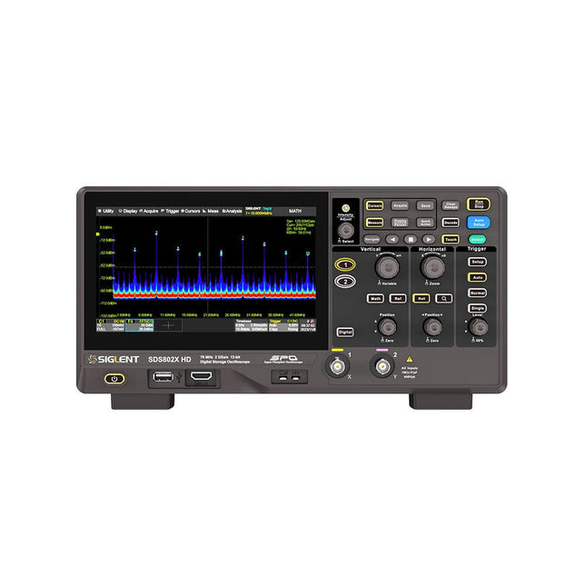
The Siglent SDS822X HD digital storage oscilloscope is based on 2 GSa/s, 12-bit Analog-Digital Converters and front ends with excellent noise floor performance. With a 200 MHz bandwidth, and a maximum record length of 100 Mpts, and the capability to analyze 2 analog channels alongside 16 digital channels, the SDS822X HD is perfectly suited for mixed signal analysis.
Features
12-bit High Resolution
12-bit Analog-Digital Convertors with sample rate up to 2 GSa/s
Front ends with 70 μVrms noise floor @ 200 MHz bandwidth
2/4 analog channels, up to 700 MHz bandwidth
SPO technology
Waveform capture rate up to 120,000 wfm/s (normal mode), and 500,000 wfm/s (sequence mode)
Supports 256-level intensity grading and color temperature display modes.
Up to 50 Mpts record length
Digital trigger system
Intelligent trigger: Edge, Slope, Pulse width, Window, Runt, Interval, Dropout, Pattern, Video (HDTV supported), Qualified, Nth edge, Delay, Setup/Hold time.
Serial bus triggering and decoder, supports protocols I²C, SPI, UART, CAN, LIN.
Segmented acquisition (Sequence) mode, dividing the maximum record length into multiple segments (up to 80,000), according to trigger conditions set by the user, with a very small dead time between segments to capture the qualifying event.
History waveform record (History) function, the maximum recorded waveform length is 80,000 frames.
Automatic measurements on 50+ parameters, supports statistics with histogram, track, trend, Gating measurement, and measurements on Math, History and Ref.
4 Math traces (2 Mpts FFT, addition, subtraction, multiplication, division, integration, differential, square root, etc.), supports formula editor.
Abundant data analysis functions such as Search, Navigate, Counter, Bode plot and Power Analysis
High Speed hardware-based Mask Test function, with Mask Editor tool for creating user-defined masks
16 digital channels (optional)
25 MHz waveform generator (optional)
7" TFT-LCD display with 1024 x 600 resolution; Capacitive touch screen supports multi-touch gestures.
Interfaces include: USB Hosts, USB Device (USBTMC), LAN (VXI-11/Telnet/Socket), Pass/Fail, Trigger Out
Built-in web server supports remote control over the LAN port using a web browser. Supports SCPI remote control commands. Supports external mouse and keyboard. Supports NTP.
Specifications
Analog Channels
2
Bandwidth
200 MHz
Vertical resolution
12-bit
Sample rate (Max.)
One channel mode: 100 Mpts/chTwo channel mode: Mpts/chFour channel mode: 25 Mpts/ch
Memory depth (Max.)
One channel mode: 50 Mpts/chTwo channel mode: 25 Mpts/ch
Waveform capture rate (Max.)
Normal mode: 120,000 wfm/sSequence mode: 500,000 wfm/s
Trigger type
Edge, Slope, Pulse width, Window, Runt, Interval, Dropout, Pattern, Video, Qualified, Nth edge, Delay, Setup/Hold time, Serial
Serial trigger and decode (Standard)
I²C, SPI, UART, CAN, LIN
Measurement
50+ parameters, statistics, histogram, trend, and track supported
Math
4 traces 2 Mpts FFT, Filter, +, -, x, ÷, ∫dt, d/dt, √, Identity, Negation, Absolute, Sign, ex, 10x, ln, lg, Interpolation, MaxHold, MinHold, ERES, Average. Supports formula editor
Data analysis
Search, Navigate, History, Mask Test, Counter, Bode plot, and Power Analysis
Digital channel (optional)
16-channel; maximum sample rate up to 1 GSa/s; record length up to 10 Mpts
USB AWG module (option)
One channel, 25 MHz, sample rate of 125 MHz, wave length of 16 kpts, isolated output
I/O
2x USB 2.0 Host, USB 2.0 Device, 10/100 M LAN, Auxiliary output (TRIG OUT, PASS/FAIL), SBUS (Siglent MSO)
Probe (Standard)
Passive probe PB470 for each channel
Display
7 TFT-LCD with capacitive touch screen (1024x600)
Included
1x Siglent SDS822X Oscilloscope
2x Passive probe (200 MHz) PP520
1x Power cord (EU)
1x USB cable
1x Certificate of calibration
1x Quick start
Downloads
Datasheet
Manual
Programming guide
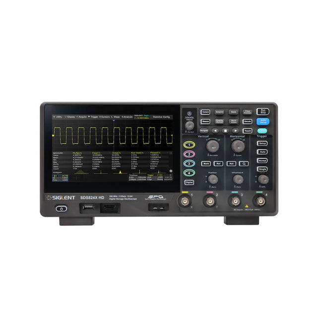
The Siglent SDS814X HD digital storage oscilloscope is based on 2 GSa/s, 12-bit Analog-Digital Converters and front ends with excellent noise floor performance. With a 100 MHz bandwidth, and a maximum record length of 50 Mpts, and the capability to analyze 4 analog channels alongside 16 digital channels, the SDS814X HD is perfectly suited for mixed signal analysis.
Features
12-bit High Resolution
12-bit Analog-Digital Convertors with sample rate up to 2 GSa/s
Front ends with 70 μVrms noise floor @ 100 MHz bandwidth
2/4 analog channels, up to 700 MHz bandwidth
SPO technology
Waveform capture rate up to 80,000 wfm/s (normal mode), and 500,000 wfm/s (sequence mode)
Supports 256-level intensity grading and color temperature display modes.
Up to 50 Mpts record length
Digital trigger system
Intelligent trigger: Edge, Slope, Pulse width, Window, Runt, Interval, Dropout, Pattern, Video (HDTV supported), Qualified, Nth edge, Delay, Setup/Hold time.
Serial bus triggering and decoder, supports protocols I²C, SPI, UART, CAN, LIN.
Segmented acquisition (Sequence) mode, dividing the maximum record length into multiple segments (up to 80,000), according to trigger conditions set by the user, with a very small dead time between segments to capture the qualifying event.
History waveform record (History) function, the maximum recorded waveform length is 80,000 frames.
Automatic measurements on 50+ parameters, supports statistics with histogram, track, trend, Gating measurement, and measurements on Math, History and Ref.
4 Math traces (2 Mpts FFT, addition, subtraction, multiplication, division, integration, differential, square root, etc.), supports formula editor.
Abundant data analysis functions such as Search, Navigate, Counter, Bode plot and Power Analysis
High Speed hardware-based Mask Test function, with Mask Editor tool for creating user-defined masks
16 digital channels (optional)
25 MHz waveform generator (optional)
7" TFT-LCD display with 1024 x 600 resolution; Capacitive touch screen supports multi-touch gestures.
Interfaces include: USB Hosts, USB Device (USBTMC), LAN (VXI-11/Telnet/Socket), Pass/Fail, Trigger Out
Built-in web server supports remote control over the LAN port using a web browser. Supports SCPI remote control commands. Supports external mouse and keyboard. Supports NTP.
Specifications
Analog Channels
4
Bandwidth
100 MHz
Vertical resolution
12-bit
Sample rate (Max.)
One channel mode: 2 GSa/sTwo channel mode: 1 GSa/sFour channel mode: 500 MSa/s
Memory depth (Max.)
One channel mode: 50 Mpts/chTwo channel mode: 25 Mpts/chFour channel mode: 10Mpts/ch
Waveform capture rate (Max.)
Normal mode: 80,000 wfm/sSequence mode: 500,000 wfm/s
Trigger type
Edge, Slope, Pulse width, Window, Runt, Interval, Dropout, Pattern, Video, Qualified, Nth edge, Delay, Setup/Hold time, Serial
Serial trigger and decode (Standard)
I²C, SPI, UART, CAN, LIN
Measurement
50+ parameters, statistics, histogram, trend, and track supported
Math
4 traces 2 Mpts FFT, Filter, +, -, x, ÷, ∫dt, d/dt, √, Identity, Negation, Absolute, Sign, ex, 10x, ln, lg, Interpolation, MaxHold, MinHold, ERES, Average. Supports formula editor
Data analysis
Search, Navigate, History, Mask Test, Counter, Bode plot, and Power Analysis
Digital channel (optional)
16-channel; maximum sample rate up to 1 GSa/s; record length up to 10 Mpts
USB AWG module (option)
One channel, 25 MHz, sample rate of 125 MHz, wave length of 16 kpts, isolated output
I/O
2x USB 2.0 Host, USB 2.0 Device, 10/100 M LAN, Auxiliary output (TRIG OUT, PASS/FAIL), SBUS (Siglent MSO)
Probe (Standard)
Passive probe PB470 for each channel
Display
7 TFT-LCD with capacitive touch screen (1024x600)
Included
1x Siglent SDS814X Oscilloscope
4x Passive probe (100 MHz) PP510
1x Power cord (EU)
1x USB cable
1x Certificate of calibration
1x Quick start
Downloads
Datasheet
Manual
Programming guide
Siglent's SDS2000X Plus series Digital Storage Oscilloscopes are available in bandwidths of 100 MHz, 200 MHz, and 350 MHz, have a maximum sample rate of 2 GSa/s, a maximum record length of 200 Mpts/ch, and up to 4 analog channels + 16 digital channels mixed-signal analysis ability.
The SDS2000X Plus series employs Siglent’s SPO technology with a maximum waveform capture rate of up to 120,000 wfm/s (normal mode, up to 500,000 wfm/s in Sequence mode), 256-level intensity grading display function plus a color temperature display mode. It also employs an innovative digital trigger system with high sensitivity and low jitter. The trigger system supports multiple powerful triggering modes including serial bus triggering. History waveform recording, Sequence acquisition, Search and Navigate functions allow for extended waveform records to be captured, stored, and analyzed. An impressive array of measurement and math capabilities, options for a 50 MHz waveform generator, as well as serial decoding, mask test, bode plot, and power analysis are also features of the SDS2000X Plus. A 10-bit acquisition mode helps to satisfy applications that require more than 8-bit resolution.
The large 10.1’’ capacitive touch screen supports multi-touch gestures, while the remote web control, mouse and external keyboard support greatly improve the operating efficiency of the SDS2000X Plus.
Features
100 MHz, 200 MHz, 350 MHz (upgradable to 500 MHz) models
Real-time sampling rate up to 2 GSa/s
Record length up to 200 Mpts
Serial bus triggering and decoder, supports I²C, SPI, UART, CAN, LIN, CAN FD, FlexRay, I²S and MIL-STD-1553B
Provide 10 bit mode, Vertical and Horizontal Zoom
Capacitive touch screen supports multi-touch gestures
Siglent SDS2000X Plus Oscilloscopes
SDS2102X Plus
SDS2104X Plus
SDS2204X Plus
SDS2354X Plus
Bandwidth
100 MHz
100 MHz
200 MHz
350 MHz
Channels
2
4
4
4
Real-time sampling rate
2 GSa/s
2 GSa/s
2 GSa/s
2 GSa/s
Capture rate
120,000 wfm/s
120,000 wfm/s
120,000 wfm/s
120,000 wfm/s
Memory depth
200 Mpts/ch
200 Mpts/ch
200 Mpts/ch
200 Mpts/ch
Included
Siglent SDS2102X Plus Oscilloscope
Passive probes
Power cord
USB cable
Manual
Downloads
Datasheet
Manual
Quick guide
Manual
Firmware
The SDS1000X-U series employs SPO (Super Phosphor Oscilloscope) technology that provides excellent signal fidelity and performance. It comes with an innovative digital trigger system with high sensitivity and low jitter, and a waveform capture rate of 400,000 frames/sec (sequence mode). The SDS1000X U also employs a 256 level intensity grading display function and a color temperature display mode not found in other models in this class.
Another powerful addition is the new 128 k point FFT math function that gives the SDS1000X-U a very high-frequency resolution when observing signal spectra. SDS1000X-U also supports searching and navigating. The features and performance of SIGLENT’s new SDS1000X-U cannot be matched anywhere else in this price class.
Features
100 MHz bandwidth
Real-time sampling rate up to 1 GSa/s
The newest generation of SPO technology
Waveform capture rates up to 100,000 wfm/s (normal mode) and 400,000 wfm/s (sequence mode)
Supports 256-level intensity grading and color temperature display modes
Record length up to 14 Mpts
Digital trigger system
Intelligent trigger: Edge, Slope, Pulse Width, Window, Runt, Interval, Time out (Dropout), Pattern
Serial bus triggering and decoding (Standard), supports protocols I²C, SPI, UART, CAN, LIN
Video trigger, supports HDTV
10 types of one-button shortcuts, supports Auto Setup, Default, Cursors, Measure, Roll, History, Display/Persist, Clear Sweep, Zoom and Print
Segmented acquisition (Sequence) mode, divides the maximum record length into multiple segments (up to 80,000), according to trigger conditions set by the user
Automatic measurement function for 38 parameters as well as Measurement Statistics, Zoom, Gating, Math, History and Reference functions
History waveform record (History) function (maximum recorded waveform length is 80,000 frames)
128 k pts FFT, supports Peaks and Markers
Math functions (FFT, addition, subtraction, multiplication, division, integration, differential, square root)
Large 7 inch TFT LCD display with 800 x 480 resolution
Downloads
Datasheet
Manual
Programming Guide