
Search results for "anycubic OR photon OR mono OR x OR uv OR resin OR sla OR 3d OR printer"
-

Elektor Digital KiCad Like A Pro – Fundamentals and Projects (E-book)
Getting started with the world’s best open-source PCB tool The latest iteration of KiCad, the world’s best free-to-use Printed Circuit Board tool, is packed with features usually found only in expensive commercial CAD tools. This modern, cross-platform application suite built around schematic and design editors, with auxiliary applications is a stable and mature PCB tool. KiCad 8 is a perfect fit for electronic engineers and makers. Here are the most significant improvements and features in KiCad 8, both over and under the hood: Modern user interface, completely redesigned from earlier versions Improved and customizable electrical and design rule checkers Theme editor allowing you to customize KiCad on your screen Ability to import projects from Eagle, CADSTART, and more Python scripting API Improved integrated SPICE circuit simulator Multi-sheet schematics Filters define selectable elements Enhanced interactive router helps you draw single tracks and differential pairs with precision New or enhanced tools to draw tracks, measure distances, tune track lengths, etc. Advanced interactive router Built-in bill of materials generator Realistic ray-tracing capable 3D viewer Customizable teardrops Plug-in manager for quick installation of themes, libraries and functionalities such as autorouters and BOM generators This book will teach you to use KiCad through a practical approach. It will help you become productive quickly and start designing your own boards. Example projects illustrate the basic features of KiCad, even if you have no prior knowledge of PCB design. The author describes the entire workflow from schematic entry to the intricacies of finalizing the files for PCB production and offers sound guidance on the process. Further full-fledged projects, of incremental difficulty, will be presented in a second book, together with a variety of advanced recipes.
€ 44,95
Members: € 40,46
-
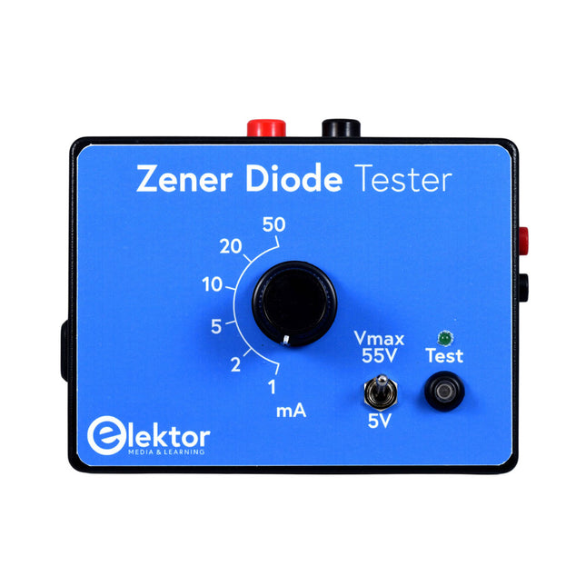
Elektor Zener Diode Tester
The Elektor Zener Diode Tester is essentially a constant-current source that can be switched in steps from 1 to 50 mA. It can be used to test Z-diodes up to a maximum of 54 V. Thanks to a 60-V step-up converter, the device can be powered by the usual 5 to 12 V. The principle of this tester is straightforward. A Z-diode or other DUT (device under test, such as an LED) is biased by an adjustable current source. The voltage across the DUT can be measured with a multimeter. The voltage of most (small) Z-diodes is specified at a current of 5 mA. Depending on the application, the voltage at other currents can also be of interest. That is why six current settings are available: 1, 2, 5, 10, 20, and 50 mA. LEDs are often specified at a current of 20 mA. What can be tested is: Whether a Z-diode is defective (short circuit or high impedance). Whether a Z-diode exhibits the correct Z-voltage. How a Z-voltage changes with different currents. What exact voltage is present at an integrated voltage reference. Whether LEDs in a series chain differ in brightness (hence the 20 mA current). What the current gain is for different base currents in (power) transistors. The kit contains all parts listed in the bill of materials including PCB and enclosure. Specifications Supply voltage 5…12 V/2 A (USB-C) Supply current (Itest = 50 mA) 1.1 A @ 5 V / 412 mA @ 12 V Selectable currents 1, 2, 5, 10, 20, and 50 mA Max. test voltage >54 V @ Itest ≥1 mA Max. output voltage 60 V @ Itest = 0 mA Voltage limit at 5 V 4.5 V @ Itest = 1 mA / 5.18 V @ Itest = 50 mA Enclosure dimensions 110 x 82 x 44 mm PCB size 105.4 x 67.3 mm Connections 4 mm banana sockets for multimeter 2 mm banana sockets for test clips USB-C socket for power supply Included Resistors R1 = 3.3 kΩ, 600 mW, 1% R2 = 0.15 Ω, 1 W, 5%, LS 12.7 mm, ø 3.5 mm R3, R8 = 180 Ω, 600 mW, 1% R4, R6, R16 = 1 kΩ, 600 mW, 1% R5, R19 = 47 kΩ, 600 mW, 1% R7 = 3.9 kΩ, 1 W, 5%, LS 12.7 mm, ø 3.5 mm R9, R10, R12 = 10 kΩ, 600 mW, 1% R11, R13 = 100 Ω, 600 mW 1% R14 = 249 Ω, 600 mW, 1% R15 = 499 Ω, 600 mW, 1% R17 = 2.49 kΩ, 250 mW, 1% R18 = 4.99 kΩ, 250 mW, 1% Capacitors C1 = 470 uF / 35 V, 20%, Ir = 1.86 A, ø 12.5 mm, LS 5 mm, ESR = 0.038 Ω (Panasonic EEUTP1V471) C2 = 1 uF / 100 V, 10%, X7R, LS 5 mm C3 = 2.2 nF / 50 V, 10%, X7R, LS 5 mm C4, C7 = 100 nF / 100 V, 10%, X7R, LS 5 mm C5 = 100 uF / 100 V, 20%, ø 14 mm max., LS 5 mm C6 = 1 nF / 100 V, 10%, X7R, LS 5 mm Inductor L1 = 100 uH, Irms = 2.4 A, Isat = 3.5 A, 0.09 Ω, radial, pitch 2.5/5/10 mm, ø 14 mm max. (Kemet SBC8-101-242) Semiconductors D1 = MUR120G, DO-41 D2, D4 = STPS3150RL, DO-201AD D3 = Z-diode, 18 V, 1.3 W (BZX85C18) D5 = Z-diode, 5.1 V, 0.5 W (1N5231B) LED1 = LED in pushbutton S1 LED2 = LED, green, 3 mm IC1 = MC34063, DIP-8 IC2 = LM4040BIZ-5.0/NOPB, TO-92 (TO-226AA-3) IC3 = TL051CP, DIP-8 T1 = BC327.25, TO-92 T2 = STP40NF10L, TO-220 T3 = IRF9510PBF, TO-220 T4 = 2N7000, TO-92 Others K1, K2, S1, S3 = 2-way screw terminal block, LS 3.5 mm, max. 1.5 mm² connected to K1 = USB-C socket, 30 V/3 A, chassis mounted, wired, 9 x 16 mm connected to K2 = Banana Connector, 2 mm, Socket, 60 VDC, Panel Mount, red (Multicomp 24.102.1) connected to K2 = Banana Connector, 2 mm, Socket, 60 VDC, Panel Mount, black (Multicomp 24.102.2) Test clip, red, 30 VAC/60 VDC (Hirschmann 931467101) Test clip, black, 30 VAC/60 VDC (Hirschmann 931467100) S1 = Pushbutton, panel mount, SPST-NO, 30 DC/100 mA, with red LED S2 = Rotary Switch, 6 position, 2 pole, 30°, 250 V/150 mA S3 = Toggle switch, panel mount, SPDT, solder lugs, 28 VDC T2, T3 = Heat sink, 15°C/W, FK 214 SA-CB Enclosure Hammond 1591XXSSBK, ABS, 110 x 82 x 44 mm Knob for S2, round shaft 6 mm, ø 21 mm, with indicator line (Multicomp CP-LB21-6-6D) 4 x Self-tapping screw #4-1/4", carbon steel, pan head Banana plug, red, 2 mm, 60 VDC (Multicomp 25.205.1) Banana plug, black, 2 mm, 60 VDC (Multicomp 25.205.2) Banana socket, black 4 mm, panel mount Banana socket, red 4 mm, panel mount for LED1, LED2 = Pin header, 1 x 2, vertical, pitch 2.54 mm for LED1, LED2 = Pin socket, 1 x 2, vertical, pitch 2.54 mm for T2, T3 = M3 screw, 10 mm, steel, pan head 2 x M3 washer, plain, steel 4 x M3 nut for IC1, IC3 = DIP-8 socket Wire, black, 0.25 mm² (24 AWG), stranded 14 x 0.15 mm, 1 m Wire, red, 0.25 mm² (24 AWG), stranded 14 x 0.15 mm, 1 m PCB 250772-1 v1.1 Links Article Elektor Labs
€ 79,95
Best Price
-

Elektor Publishing The BeagleY-AI Handbook
A Practical Guide to AI, Python, and Hardware Projects Welcome to your BeagleY-AI journey! This compact, powerful, and affordable single-board computer is perfect for developers and hobbyists. With its dedicated 4 TOPS AI co-processor and a 1.4 GHz Quad-core Cortex-A53 CPU, the BeagleY-AI is equipped to handle both AI applications and real-time I/O tasks. Powered by the Texas Instruments AM67A processor, it offers DSPs, a 3D graphics unit, and video accelerators. Inside this handbook, you‘ll find over 50 hands-on projects that cover a wide range of topics—from basic circuits with LEDs and sensors to an AI-driven project. Each project is written in Python 3 and includes detailed explanations and full program listings to guide you. Whether you‘re a beginner or more advanced, you can follow these projects as they are or modify them to fit your own creative ideas. Here’s a glimpse of some exciting projects included in this handbook: Morse Code Exerciser with LED or BuzzerType a message and watch it come to life as an LED or buzzer translates your text into Morse code. Ultrasonic Distance MeasurementUse an ultrasonic sensor to measure distances and display the result in real time. Environmental Data Display & VisualizationCollect temperature, pressure, and humidity readings from the BME280 sensor, and display or plot them on a graphical interface. SPI – Voltmeter with ADCLearn how to measure voltage using an external ADC and display the results on your BeagleY-AI. GPS Coordinates DisplayTrack your location with a GPS module and view geographic coordinates on your screen. BeagleY-AI and Raspberry Pi 4 CommunicationDiscover how to make your BeagleY-AI and Raspberry Pi communicate over a serial link and exchange data. AI-Driven Object Detection with TensorFlow LiteSet up and run an object detection model using TensorFlow Lite on the BeagleY-AI platform, with complete hardware and software details provided.
€ 44,95
Members: € 40,46
-
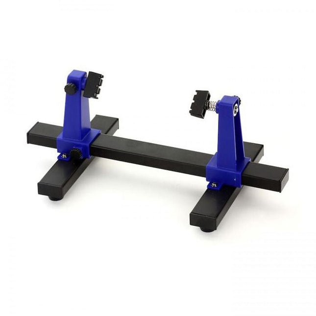
Zhongdi ZD-11E PCB Holder
This adjustable circuit board holder is ideal for clamping PCB for soldering, desoldering or rework. Features 2 adjustable grips on a retractable stand to accommodate various board sizes. The adjustable clamps allow the PCB to rotate 360 degrees and stay set in any position. The base of this rigid metal stand features four rubber feet to ensure stability. Specifications Product size 30 x 16.5 x 12.5 cm Max. holding size 20 x 14 cm Weight 450 g
€ 7,95
-

Elektor 11-12/2026 (DE)
Diese Ausgabe steht allen GOLD- und GREEN-Mitgliedern auf der ElektorMagazine-Website zum Download bereit! Sie sind noch kein Mitglied? Hier klicken! KI-Tools für das Hardware-PrototypingWas hilft, was nicht – und wo der Entwickler noch gebraucht wird ZSWatch – von der Idee zum ProduktTeil 1: Eine vollkommen offene Smartwatch Dreifach-KlangregelungHigh-End – für das gewisse Etwas electronica Fast Forward 2026Zehn Jahre Innovation Mikrocontroller-PrototypingEin Überblick über beliebte Boards Prototyping-SteckbretterBemerkenswerte Bauteile – die Serie Für den Orbit bauenEin Leitfaden für Maker zur COTS-Auswahl, Strahlungsresistenz und Missionsarchitektur Thermomanagement für zuverlässige ElektronikWenn jedes Grad zählt Vom Konzept zum ProduktEntwicklung marktreifer Embedded-Systeme EMI-Ferrite als DCF77-AntennenErsatz für klassische Ferritantennen-Kerne Einem Roboterarm das Sehen und Bewegen beibringenKI-gesteuerte Manipulation mit einem 3D-gedruckten Roboter Elektor ist 65Projekte aus früheren November/Dezember-Ausgaben Loop-Antenne mit RF BricksTeil 2: Signalverarbeitung Vom Prototyp zur ProduktionPraxis-Tipps aus der Elektor-Community Projekt-UpdatesFeedback, Ideen, Korrekturen Handlicher AudiogeneratorEin Referenzsignalquelle für die schnelle Einrichtung von Audiosystemen AudiotronicsMehr zu Verzerrungen und ein Pegelanpassungsverstärker 2026: Eine KI-OdysseeWenn KI beginnt, KI zu erschaffen Wireless Workshop (2)Freigeschaltetes Funkmodul: 2,4-GHz-Transceiver nRF24L01P Der digitale Weg Die Entwicklung einer Open-Source-SmartwatchDaniel Kampert über die ZSWatch, offene Hardware und technische Kompromisse Wie man sich auf professionelle SMD-Bestückung vorbereitet Entwicklung jenseits der WerkbankSystemintegration, Fehlerbehebung und Praxistests Avionik-InstrumentensimulatorESP32-S3-basiert, mit rundem HMI-Display
€ 15,90
-
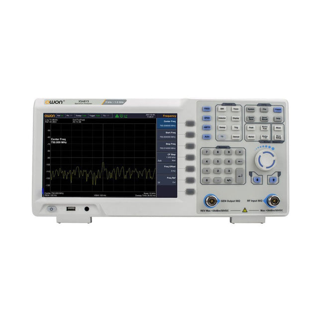
OWON OWON XSA815-TG Spectrum Analyzer (9 kHz – 1.5 GHz)
The OWON XSA815-TG (9 kHz-1.5 GHz) is a cost effective spectrum analyzer with tracking generator included and a frequency resolutions of 1 Hz. Features Frequency Range from 9 kHz to 1.500009 GHz 9-inch display 9 kHz to 1 MHz -95 dBm Displayed Average Noise Level, 1 MHz to 500 MHz 140 dBm (Typical), <-130 dBm Phase Noise -10 kHz <-80 dBc/Hz 100 kHz <-100 dBc/Hz 1 MHz <-115 dBc/Hz Resolution Bandwidth (-3 dB): 1 Hz to 1 MHz, in 1-3-5-10 sequence Tracking Generator Kit: 100 kHz to 1.500009 GHz Specifications Frequency Range 9 kHz to 500.009 MHz Frequency Resolution 1 Hz Frequency Span 9 kHz to 1.500009 GHz Span Range 0 Hz, 100 Hz to max frequency of instrument Span Uncertainty ±span / (sweep points-1) SSB Phase Noise (20°C to 30°C, fc=1 GHz) Carrier Offset 10 kHz <-80 dBc/Hz | 100 kHz <-100 dBc/Hz | 1 MHz <-115 dBc/Hz Resolution Bandwidth (-3 dB) 1 Hz to 1 MHz, in 1-3-5-10 sequence RBW Accuracy <5% typical Resolution Filter Shape Factor (60 dB: 3 dB) <5 typical Video Bandwidth (-3 dB) 10 Hz to 1 MHz, in 1-3-5-10 sequence Amplitude measurement range DANL to +10 dBm, 100 kHz to 10 MHz, Preamp Off DANL to +20 dBm, 10 MHz to 1.5 GHz, Preamp Off Reference Level -80 dBm to +30 dBm, 0.01dB by step Preamp 20 dB, nominal, 100 kHz to 1.5 GHz Input Attenuator 0 to 40 dB, 1 dB by step Display Average Noise Level Input attenuation = 0 dB, RBW = VBW = 100 Hz, sample detector, trace average ≥ 50, 20°C to 30°C, input impedance = 50 Ω) Preamp Off 9 kHz to 1 MHz -95 dBm (Typical), <-88 dBm Preamp Off 1 MHz to 500 MHz -140 dBm (Typical), <-130 dBm Preamp On 100 kHz to 1 MHz -135 dBm (Typical), <-128 dBm Preamp On 1 MHz to 500 MHz -160 dBm (Typical),<-150 dBm Tracking Generator (optional) Frequency Range 100 kHz to 1.500009 GHz Output power level range -40 dBm to 0 dBm Output level resolution 1 dB Output flatness Relative to 50 MHz | ±3 dB Tracking generator spurious Harmonic spurious -30 dBc (Tracking generator output power -10 dBm) Non-harmonic spurious -40 dBc (Tracking generator output power -10 dBm) Tracking generator to input terminal isolation -60 dB (Tracking generator output power 0 dBm) Tracking generator to input terminal isolation -60 dB (Tracking generator output power 0 dBm) Tracking generator to input terminal isolation -60 dB (Tracking generator output power 0 dBm) Dimensions 375 x 185 x 120 mm Weight 3.7 kg Included 1x XSA815-TG 1x 220 V AC power cord 1x USB Cable 1x Quickstart guide Downloads Quick Guide Specifications
€ 907,50
-
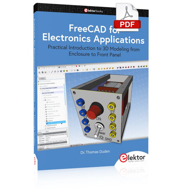
Elektor Digital FreeCAD for Electronic Applications (E-book)
Practical Introduction to 3D Modeling from Enclosure to Front Panel Embedding a vintage component, creating a professional looking home for a circuit board, or even designing a complex apparatus complete with a chassis – these and many other challenges turn into a stimulating pleasure with FreeCAD. Once you have internalized the basic processes, there are virtually no limits to your imagination. Starting to use a new software is never straightforward – especially with a tool as versatile as FreeCAD. Manageable, but at the same time easily usable individual components provide the starting point in this book. Putting these components together later results in assemblies. In the FreeCAD universe, a workable trajectory is demonstrated. The described procedure is illustrative so the examples are easily applied to custom tasks. The devices were made by the author and illustrated with photos. Creating a 3D design is requiring some effort but the initial investment pays off soon. Besides the impressive spatial representation of the projects, the extracted drawings yield a solid base for documentation and production. Extended FreeCAD capabilities like the unfolding of sheet metal parts enormously add to efficiency and pushes models forward into practical assembly. Soon you will definitely not want to do without FreeCAD!
€ 34,95
Members: € 31,46
-

OWON OWON XDM1041 True RMS Multimeter
The OWON XDM1041 is a fast, high-precision digital True RMS benchtop multimeter with a high-resolution 3.5-inch LCD and 50,000 counts. Its DC voltage accuracy is up to 0.05% and it can measure up to 65 values per second. Features 3.5“ high-resolution LCD (480x320 pixels) 55000 counts, DC voltage accuracy up to 0.05% Up to 65 readings per second Dual line display supported Trend analysis accessible in chart mode AC True RMS measurements (bandwidth: 20 Hz – 1 kHz) SCPI support: Remote control the multimeter through PC software via USB port Data record function, you can record the measured data into internal memory, and then read and process the recorded data with your computer. Specifications Measurement Range Resolution Accuracy DC Voltage 50.000 mV 0.001 mV 0.1% +10 500.00 mV 0.01 mV 0.05% +5 5.0000 V 0.0001 V 0.05% +5 50.000 V 0.001 V 0.05% +5 500.00 V 0.01 V 0.1% +5 1000.0 V 0.1 V 0.1% +10 AC Voltage 500 mV~750 V 20 Hz~45 Hz 1% +30 45 Hz~65 Hz 0.5% +30 65 Hz~1 KHz 0.7% +30 DC Current 500 uA 0.01 uA 0.15% +20 5000 uA 0.1 uA 0.15% +10 50 mA 0.001 mA 0.15% +20 500 mA 0.01 mA 0.15% +10 5 A 0.0001 A 0.5% +10 10 A 0.001 A 0.5% +10 AC Current 500 uA~500 mA 20 Hz~1 KHz 0.5% +20 5 A-10 A 1.5% +20 Resistance 500 Ω 0.01 Ω 0.15% +10 5 KΩ 0.0001 KΩ 0.15% +5 50 KΩ 0.001 KΩ 0.15% +5 500 KΩ 0.01 KΩ 0.15% +5 5 MΩ 0.0001 MΩ 0.3% +5 50 MΩ 0.001 MΩ 1% +10 Frequency 10.000 Hz~60 MHz / ±(0.2% +10) Capacitance 50 nF~500 uF / 2.5% +10 5 mF~50 mF 5% +10 Diode 3.0000 V 0.0001 V / Continuity 1000 Ω 0.1 Ω Adjustable threshold Temperature K type, PT100 Max Display 55,000 counts Data-logging Function Logging Duration 15ms~9999.999s Logging Length 1,000 points Display 3.5“ TFT LCD (480x320 pixels) Power supply 230 V AC mains voltage Dimensions 200 x 88 x 150 mm Weight approx. 0.5 kg Included 1x OWON XDM1041 Multimeter 1x Power cord 2x Test leads 1x Fuse 1x USB cable 1x Manual Downloads Programming Manual PC Software
€ 94,38
-

Elektor Digital FreeCAD für Elektroniker (PDF)
Praktische Einführung in 3D-Modellierung vom Gehäuse bis zu Frontplatten Ein historisches Bauteil einbetten, eine professionell anmutende Heimstätte für eine Leiterplatte schaffen oder ein komplexes Gerät mit Chassis konstruieren – diese und viele andere Herausforderungen werden mit FreeCAD zu einem anregenden Vergnügen. Hat man die grundlegenden Prozesse erst einmal verinnerlicht, sind der Fantasie praktisch keine Grenzen mehr gesetzt. Der Einstieg in ein neues Programm ist immer schwierig – besonders wenn es sich um ein so vielfältiges Werkzeug wie FreeCAD handelt. Überschaubare, aber zugleich gut verwendbare Einzelteile liefern in diesem Buch den Anfangspunkt. Das Zusammensetzen dieser Komponenten führt später zu Baugruppen. In der Vielfalt der Möglichkeiten von FreeCAD wird ein gangbarer Weg gezeigt. Das beschriebene Vorgehen ist exemplarisch – die Beispiele lassen sich daher leicht auf eigene Aufgaben anwenden. Die Geräte wurden vom Autor angefertigt und mit Fotos illustriert. Eine 3D-Konstruktion erfordert etwas Aufwand, der sich aber lohnt: Neben einer beeindruckenden Darstellung von Projekten wird zugleich die Möglichkeit geliefert, z. B. Blechteile zur Fertigung abzuwickeln und für die Werkstatt aussagekräftige Zeichnungen zu exportieren. Schon bald werden Sie auf FreeCAD nicht mehr verzichten wollen!
€ 34,80
Members: € 31,32
-

Elektor Digital Elektor Circuit Special 2026 (PDF) EN
Elektor GREEN and GOLD members can download their digital edition here. Not a member yet? Click here. A Current Source for Testing (Z-)DiodesChecking Z-Diodes from 1 to 54 V @ 1 to 50 mA ESD Strap TesterA Bench Tool with Pass, Borderline, and Fail Indication Power Supply Transient Response TesterA Repeatable Step-Load Generator for Bench Power Supplies Euclidean Sequencer Without a MicrocontrollerTrigger Patterns and CV Sequences with Simple CMOS Logic LED Flashing Light for Gates and More with an Audible Alert Need PCBs? The Elektor PCB Service Has You Covered. Toothbrush TimerUsing a Tiny PIC A Contactless Magnetic Combination LockWith the AS5600 Rotary Position Sensor Low-Noise Battery-Powered PreamplifierFor Dynamic Microphones The Arduino Nano TestLabMeasurement, Control, and Regulation Rhythmic Bass LightEmphasize the Rhythm of Your Music Low-Cut FilterNo Risk of Audio Feedback on Your System Precise 1 Hz Square Wave Generator for BreadboardsA Reliable CMOS-Based Clock Source 555 Upside DownDuty Cycles Down to Zero From Halfgeleidergids to Circuit Specials65 Years of Electronics Innovation Electrical IsolationCAN Interface with Digital Isolator and Power Module SpongillatorA Sponge-Based Oscillator True Random Number GeneratorWith Integrated Chi-Square Test 3D Viewer for HTML pagesSimple, and Almost Without Code Programming with TLScriptA Scripting Language for Measurement, Testing, and Control Circuit Design: Tips from Experts FeedbackWhat Is It and Why Is It Important? One Board, Endless Ideas: Arduino UNO QFrom Retro Gaming to Real-Time Environmental Monitoring How to Fix a Donut Antenna Standby KillerA Real On/Off Switch for Your TV Battery TestingMeasuring Batteries with the Arduino Nano Power Supply for Audio Power AmplifiersA Good Power Supply Without Mains Hum Prototyping Boards for RFFast Setups with DIY Prototyping Boards T3 Surge ProtectionA Type 3 Spike Suppressor for Your Sensitive Equipment IoT Room Thermostat BoardWith ESP32-C3/S3-Based Xiao MCU module From Rigid to SmartFlexible and Printed Electronics — Between Vision and Industrial Reality
€ 9,50
-
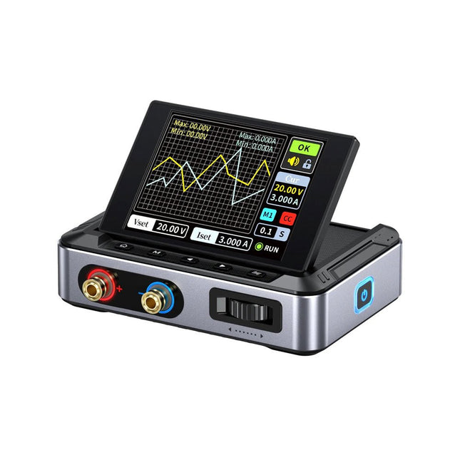
FNIRSI FNIRSI DPS150 DC Power Supply (150 W)
The FNIRSI DPS150 is a high-performance adjustable DC power supply that features a USB-C input interface and multiple power supply modes, allowing precise adjustment of output voltage (0-30 V) and current (0-5 A). It provides efficient, low-consumption, and stable output, equipped with multiple safety protection functions including overvoltage, overcurrent, overload, overheating, and reverse connection. It can be flexibly applied to serial connection of multiple devices, with rich and user-friendly display and operation, compact and portable design, meeting various application needs. Features 30 V, 5 A, 150 W variable DC power with 0.01 V, 0.001 A precision, CC/CV modes, and <20 mV ripple to protect sensitive electronics. Supports PC, QC, and DC inputs with programmable outputs and 6 preset voltage/current settings. Compatible with 4 mm banana plugs, U-shaped terminals, and copper wires for various equipment. 8 safety mechanisms including overvoltage, current, short circuit, and overheating protection. 2.8-inch HD IPS screen with 90° flip, numerical and curve displays for easy monitoring. Small, space-saving design for use in labs, repairs, and DIY projects. Specifications Input Voltage 5~32 V DC Input Current 100 mA-5 A Output Voltage 0-30 V Output Current 0~5 A Output Power 0-150 W Input Way PD fast charger QC fast charger Power bank DC power adapters Operating Environment 0-40°C Load Regulation 0.49% Full Load Efficiency 96.30% Display 2.8 inch (320 x 240) Dimensions 106 x 76 x 28 mm Weight 178 g Included 1x DPS150 Power Supply 2x Alligator clip wires (black & red) 1x Micro USB cable 1x Manual Downloads Manual Firmware V0.0.1
€ 59,00
-

Elektor Digital Elektor Special: Arduino Shields (PDF) DE
Verwirklichen Sie Ihre Projekt-Träume: Der Kilometerzähler fürs Hamsterrad, eine vollautomatische Steuerung Ihrer Ameisenfarm mit Webinterface, oder den Sandwich-O-Mat – eine Maschine, die Sandwich-Toasts nach Wahl belegt und überbackt. Mit dem Arduino und der DIY- oder Maker-Bewegung wurde nicht nur der Einstieg in die Mikrocontroller-Programmierung kinderleicht, auch eine zweite Entwicklung fand statt: Findige Entwickler brachten kleine Boards – sogenannte Shields oder Module – auf den Markt, die den Einsatz von zusätzlicher Hardware stark vereinfachten. Die kleinen Baugruppen enthalten alle wichtigen elektronischen Teile, um mit ein paar Steckkabeln an den Mikrocontroller angeschlossen zu werden, so dass ein frickeliger und aufwändiger Aufbau auf dem Steckboard entfällt. Zudem ist es so möglich, auch winzig kleine Bauteile zu handhaben, die keine Anschlussbeinchen mehr haben (sogenannte SMDs). Enthaltene Projekte Arduino sucht Anschluss BMP, Einführung in Bibliotheken und I²C Mit dem Mehrzweck-Shield I/O-Grundlagen kennenlernen I²C-LCD-Adapter und Punktmatrixanzeigen LCD Keypad Shield Level-Konverter W5100: Internetanbindung I/O-Erweiterungs-Shields Relais und Solid-State-Relais Das Multi-Funktions-Shield: eine universelle Bedieneinheit SD-Kartenleser über SPI anbinden Tasten und 7-Segmentanzeigen 16-Bit ADC DAC MCP4725 16-fach PWM Servo-Treiber MP3-Player GPS-Datenlogger mit SD-Karte Touch-Sensor Joystick SHT31: Temperatur und Luftfeuchtigkeit UV A-Sensor VEML6070 VL53L0X Time-of-Flight Ultraschallsensor-Entfernungsmesser LED-Punktmatrixanzeige mit MAX7219 RTC DS3231 Port-Expander MCP23017 433 MHz Funk MPU-650: Gyroskop Beschleunigungssensor ADXL345 WS2812 RGB-LEDs Spannungsversorgung MQ-xx Gassensoren CO2-Gassensor ACS712 Stromstärkesensor INA219 Stromstärkesensor L298 Motortreiber MFRC522 RFID 28BYJ-48 Stepper-Motor TMC2209 Silent-Step-Stick X9C10x Digitales Poti Farb-TFT-Display mit ST7735 e-Paper Display Bluetooth Geigerzähler SIM800L GSM-Modul I²C-Multiplexer Controller Area Network
€ 11,90
Members: € 10,71


