
Search results for "050179 OR 2"
-
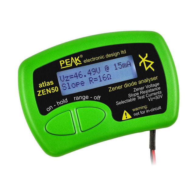
Peak Peak Atlas ZEN50 Zener Diode Analyzer
The Peak Atlas ZEN50 is ideal for testing Zener diodes (including avalanche diodes), transient suppressors, LEDs and LED strings. It generates constant current pulses (selectable from 2 mA, 5 mA, 10 mA and 15 mA) at voltages from 0 V to 50 V. So even high voltage Zeners or high voltage LED strings can be tested. Test currents are supplied in narrow pulses to ensure that the component under test remains at a constant temperature. The voltage of the part is displayed on the screen together with the test current and also a measure of the component's slope resistance (also known as dynamic impedance). Specifications Analyzer type Zeners, LEDs, TVS etc Test currents 2 mA, 5 mA, 10 mA, 15 mA Voltage range 0.00 to 50.00 V Slope resistance range 0 to 8000 Ohms Battery type Single AAA (supplied). Life typically 1400 ops Test method Triple pulse burst @ 10pps (typ) Test current duty cycle 3% Display type Alphanumeric LCD (with backlight) Included Peak Atlas ZEN50 Zener Diode Analyzer Fitted flexible test leads with gold plated crocs Comprehensive illustrated user guide AAA Alkaline battery Downloads Datasheet (EN) User Guide (EN) User Guide (FR) User Guide (DE) User Guide (IT)
€ 85,91
-

Elektor Digital Röhren 2 (PDF)
Auf 100 Seiten finden Sie interessante und informative Themen zu Röhrentechnik. Unter anderem werden die nachfolgenden Fragen beantwortet: Wie verhalten sich Röhren in Gitarrenverstärkern? Welche Vorstufenröhre ist die richtige? Welchen Einfluss hat die Qualität des Vakuums? Sind Röhrenmikrofone noch immer das Maß aller Dinge? Bauprojekte sind u. a.: Mikrofonvorverstärker in Röhrentechnik Experimentiernetzteil für Röhren Federhall Wah-Wah HiFi-Endstufe für Einsteiger
€ 15,90
Members: € 14,31
-

Elektor Publishing Wireless Power Design
From Theory to Practical Applications in Wireless Energy Transfer and Harvesting Wireless power transmission has gained significant global interest, particularly with the rise of electric vehicles and the Internet of Things (IoT). It’s a technology that allows the transfer of electricity without physical connections, offering solutions for everything from powering small devices over short distances to long-range energy transmission for more complex systems. Wireless Power Design provides a balanced mix of theoretical knowledge and practical insights, helping you explore the potential of wireless energy transfer and harvesting technologies. The book presents a series of hands-on projects that cover various aspects of wireless power systems, each accompanied by detailed explanations and parameter listings. The following five projects guide you through key areas of wireless power: Project 1: Wireless Powering of Advanced IoT Devices Project 2: Wireless Powered Devices on the Frontline – The Future and Challenges Project 3: Wireless Powering of Devices Using Inductive Technology Project 4: Wireless Power Transmission for IoT Devices Project 5: Charging Robot Crawler Inside the Pipeline These projects explore different aspects of wireless power, from inductive charging to wireless energy transmission, offering practical solutions for real-world applications. The book includes projects that use simulation tools like CST Microwave Studio and Keysight ADS for design and analysis, with a focus on practical design considerations and real-world implementation techniques.
€ 39,95
Members: € 35,96
-

JOY-iT JOY-iT PS1440-C-Pro Programmable Laboratory Power Supply with RS485 (1440 W)
With the JOY-iT PS1440-C-Pro, you get a programmable laboratory power supply that delivers DC voltages ranging from 0.01 to 60 V and DC currents from 0.01 to 24 A at the voltage output. The intuitive control panel allows you to program, store, and recall up to 9 different DC voltage settings. You can also configure individual protection and limiting functions—such as overvoltage protection. All settings are easily adjusted via the keypad and/or rotary control and are clearly shown on the high-resolution 2.4" color display. For enhanced connectivity, the PS1440-C-Pro includes an RS485 interface for robust, long-distance communication. This makes it ideal for complex setups where signal stability, noise immunity, and reliable data transfer are critical. The included connector ensures a secure connection, improving the overall reliability and performance of your laboratory equipment setup. Features Complete device ready for immediate use RS485 interface Battery charging function Values can be entered conveniently via keypad Over current & over voltage protection adjustable Integrated RTC, NTC temperature sensor Included detailed documentation in English, German & French Specifications Input voltage 230 V Output voltage 060 V Output current 0-24 A Output power 0-1440 W Input voltage accuracy ±1% +5 digits Output voltage accuracy ±0.3% +3 digits Output current accuracy ±0.5% +5 digits Battery voltage ±0.5% +3 digits Input voltage measurement resolution 0.01 V Output voltage measurement resolution 0.01 V Current measurement resolution 0.01 V Battery voltage measurement resolution 0.01 V Response time in constant voltage mode 2 ms @ 0.1-5 A Load regulation in constant voltage mode ±0.1% +2 digits Load regulation in constant current mode ±0.1% +3 digits Measuring range electric charge 0-9999.99 Ah Measuring range energy 0-9999.99 Wh Statistical errors in electric charge & energy ±2% Output ripple 100 mV VPP @ 12 V150 mV VPP @ 24 V Sensor temperature detection range −10~100°C (0-200°F) Sensor temperature detection accuracy ±3°C (±6°F) Working mode Step-down operation Screen brightness setting Level 0-5, 6 levels in total Permissible working temperature −10~40°C (0-104°F) Dimensions 170 x 93 x 340 mm Included JOY-iT PS1440-C Power Supply 2-pin connector for RS485 interface Power cord Manual Downloads Datasheet MODBUS Protocol PC Software Driver for Windows
€ 499,00
Members: € 449,10
-

Elektor Digital Wireless Power Design (E-book)
From Theory to Practical Applications in Wireless Energy Transfer and Harvesting Wireless power transmission has gained significant global interest, particularly with the rise of electric vehicles and the Internet of Things (IoT). It’s a technology that allows the transfer of electricity without physical connections, offering solutions for everything from powering small devices over short distances to long-range energy transmission for more complex systems. Wireless Power Design provides a balanced mix of theoretical knowledge and practical insights, helping you explore the potential of wireless energy transfer and harvesting technologies. The book presents a series of hands-on projects that cover various aspects of wireless power systems, each accompanied by detailed explanations and parameter listings. The following five projects guide you through key areas of wireless power: Project 1: Wireless Powering of Advanced IoT Devices Project 2: Wireless Powered Devices on the Frontline – The Future and Challenges Project 3: Wireless Powering of Devices Using Inductive Technology Project 4: Wireless Power Transmission for IoT Devices Project 5: Charging Robot Crawler Inside the Pipeline These projects explore different aspects of wireless power, from inductive charging to wireless energy transmission, offering practical solutions for real-world applications. The book includes projects that use simulation tools like CST Microwave Studio and Keysight ADS for design and analysis, with a focus on practical design considerations and real-world implementation techniques.
€ 32,95
Members: € 29,66
-
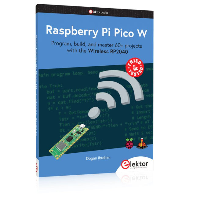
Elektor Publishing Raspberry Pi Pico W (Book)
Program, build, and master 60+ projects with the Wireless RP2040 The Raspberry Pi Pico and Pico W are based on the fast, efficient, and low-cost dual-core ARM Cortex M0+ RP2040 microcontroller chip running at up to 133 MHz and sporting 264 KB of SRAM and 2 MB of Flash memory. Besides spacious memory, the Pico and Pico W offer many GPIO pins, and popular peripheral interface modules like ADC, SPI, I²C, UART, PWM, timing modules, a hardware debug interface, and an internal temperature sensor. The Raspberry Pi Pico W additionally includes an on-board Infineon CYW43439 Bluetooth and Wi-Fi chipset. At the time of writing this book, the Bluetooth firmware was not yet available. Wi-Fi is however fully supported at 2.4 GHz using the 802.11b/g/n protocols. This book is an introduction to using the Raspberry Pi Pico W in conjunction with the MicroPython programming language. The Thonny development environment (IDE) is used in all of the 60+ working and tested projects covering the following topics: Installing the MicroPython on Raspberry Pi Pico using a Raspberry Pi or a PC Timer interrupts and external interrupts Analogue-to-digital converter (ADC) projects Using the internal temperature sensor and external sensor chips Using the internal temperature sensor and external temperature sensor chips Datalogging projects PWM, UART, I²C, and SPI projects Using Bluetooth, WiFi, and apps to communicate with smartphones Digital-to-analogue converter (DAC) projects All projects are tried & tested. They can be implemented on both the Raspberry Pi Pico and Raspberry Pi Pico W, although the Wi-Fi-based subjects will run on the Pico W only. Basic programming and electronics experience are required to follow the projects. Brief descriptions, block diagrams, detailed circuit diagrams, and full MicroPython program listings are given for all projects.
€ 44,95
Best Price
-

Elektor Labs Elektor Low-Noise Lab Power Supply
The Elektor Low-Noise Lab Power Supply is a fully analogue, adjustable, medium-power symmetrical bench supply that contains no switching or digital components. It provides an output voltage adjustable between 0 V and ±22 V, and an output current adjustable from 0 A to 1 A. Because it avoids any form of switching circuitry, the design delivers extremely low noise. To display both output voltages and currents, four miniature moving-coil panel meters are used. Most modern laboratory power supplies and AC adapters employ switch-mode techniques. Even the best examples inevitably exhibit high-frequency ripple and other switching artefacts on their output, which can interfere with the testing of sensitive analogue circuits and disturb low-level measurements. To overcome this, the concept here is a completely analogue power supply. Although less efficient than its switch-mode counterparts, the reduced efficiency is of little importance for test-bench use and ensures cleaner, more reliable measurement results. Because many analogue circuits require a symmetrical supply, this design delivers positive and negative output voltages of equal magnitude. A small amount of adjustment is available to compensate for any imbalance. Naturally, a variable current-limit function is also included. The kit includes the components required to build the power supply, except for the transformers. Specifications Output Voltage 0…+22 V, 0, −22 V Output Current 0…+1 A, 0…−1 A Noise −85 dBV, (at 0.95 A/20 V, B = 22 kHz) −84 dBV (at 0.95 A/20 V, B > 500 kHz) Ripple 50 µVRMS (at 950 mA/20 V, B = 22 kHz, mainly 100 Hz component) Included 3x PCBs: Regulator (PCB-1), Mains Filter (PCB-2) and Transformer (PCB-3) All the components except the AC transformers 4x moving-coil meters Additional parts for wiring (wires, banana sockets, IEC Power entry module, etc.) Not included The three AC transformers An enclosure Parts List For the Regulator PCB (240386-1) Resistors (250 mW, 1%) R1 = 12 Ω R2, R8, R37, R62 = 1 MΩ R3, R7, R10, R13, R17, R20, R22, R30, R35, R42, R45, R47, R55, R60 = 100 Ω, 600 mW R4, R5 = 4.7 kΩ R6 = 100 kΩ R9, R12, R14, R36, R38, R39, R61, R63, R66, R72, R78, R79 = 10.0 kΩ, 600 mW R11 = 9.76 kΩ, 600 mW R15, R40 = 44.2 kΩ, 600 mW R16, R41, R77 = 1 kΩ R18, R43 = 1.5 kΩ, 1 W, 5% R19, R44 = 470 Ω, 1 W, 5% R21, R46 = 330 Ω, 600 mW R23, R24, R48, R49 = 1.0 Ω, 1 W R25, R50 = 1 kΩ, 1 W, 5% R26, R28, R51, R53 = 1.000 kΩ 0.1%, 15 ppm/C R27, R29, R52, R54 = 10.00 kΩ 0.1%, 15 ppm/C R31, R56 = 1.2 kΩ, 1 W, 5% R32, R57 = 47 kΩ R33, R58 = 270 Ω R34, R59 = 27 kΩ R64, R69 = 12.0 kΩ R65 = 3.0 kΩ, 600 mW R67, R80 = 470 Ω, 600 mW R68, R70 = 6.8 kΩ, 600 mW R71 = 30.0 kΩ,, 600 mW R73, R74, R75, R76 = 10 MΩ P1, P2, P3 = 10 kΩ, 200 mW, 20%, potentiometer, 1 turns, single, lin., panel mount P4, P5 = 500 Ω, 500 mW, 10%, trimmer, 25 turns, 3296Y-1-501LF Bourns P6, P7 = 10 kΩ, 500 mW, 10%, trimmer, 25 turns, 3296Y-1-501LF Bourns Capacitors C1 = 100 nF, 50 V, 10%, ceramic X7R, LS 5 mm C2, C3, C6, C7, C30 = 10 µF, 63V, 20%, LS 2.5 mm, 3000hours@105°C C4, C5, C8, C9, C13, C14, C18, C19, C23, C24, C28, C29, C31, C32, C38, C39 = 100 nF, 250 V, 10%, PET, LS 7.5 mm C10, C20 = 47 nF, 100 V, 5%, PET, LS 5 mm C11, C21 = 10 nF, 100 V, 5%, PET, LS 5 mm C12, C22 = 220 µF, 35 V, 20%, 0.024 Ω, LS2.5/3.5 mm, Ir 3.4 A, 2000hours@125°C, polymer C15, C25 = 120 µF, 50 V, 20%, ESR 0.02 Ω, Diam. 10 mm max., LS 5 mm C16, C26 = 15 nF, 100 V, 5%, PET, LS 5 mm C17, C27 = 47 nF, 100 V, 5%, PET, LS 5 mm C33, C34 = 22 µF, 50 V, 20%, LS 2 mm, 10000 hours @ 105°C C35, C36, C44, C45 = 1 µF, 100 V, 10%, LS 5 mm, ceramic X7R C37 = 100 uF, 50 V, 20%. LS 3.5 mm C40, C41, C42, C43, C46, C47, C48, C49 = 1000 µF, 50 V, 20%, LS 5/7.5 mm, Ir 3.32 A, 10000hours@105°C, D 16 mm C50, C51, C52, C53 = 47 nF, 100 V, 10%, ceramic X7R, LS 5 mm Inductors L1, L2 = 4.7 µH, 3.2 A, 0.033 Ω, LS 5 mm, RLB0914-4R7ML Bourns L3 = Commom mode choke, 14.5 mH, 3 A, SSRH24NH-30145 Kemet Semiconductors D1, D2, D3, D4, D5, D9, D10, D11, D15 = BAT85, DO-34 D6, D7, D12, D13 = SR560, DO-201AD D8, D14, D16 = 1N4148, DO-35 D17 = Zenerdiode, 5.6 V, 0.5 W, DO-41 D18, D19 = 1N4004, DO-41 D20, D21 D22, D23 = V30100CI-M3/P, dual common cathode, TO-220 D24 = Zener diode, 30 V, 1 W, DO-41 LED1, LED2 = LED, red, T-1 (3 mm) LED3, LED4 = LED, green, T-1 (3 mm) TVS1, TVS2 = BZW50-33B, R6 T1, T2, T4 = BC337.25, TO-92 T3 = NJW0302G, TO-3P T5, T6, T8 = BC327.25, TO-92 T7 = NJW0281G, TO-3P T9 = BD139, TO-126 (SOT-32) IC1 = LM334Z, TO-92 IC2 = LM4040AIZ-5.0/NOPB, TO-92 (TO-226AA-3) IC3, IC4 = OPA2992IDR, SOIC-8 IC5, IC6 = OPA4992IDR, SOIC-14 IC7 = OPA992IDBVR, SOT-23-5 IC8 = LM339N, DIP-14 IC9 = LM317, TO-220 IC10 = LM337, TO-220 Others F1, F2 = 5×20 mm fuse, 1.6 A, fast acting HS1, HS2 = Heatsink MC33271 (for T3/T7), 2.7°C/W, PCB mount, height 63.5 mm K1, K4 = 3-way screw terminal block, LS 3.5 mm, max. 1.5 mm² K2, K3 = 3-way screw terminal block, LS 3.5 mm, max. 1 mm² M1, M3 = Moving coil meter, Range 30 V, type 91C4, 45×45 mm M2, M4 = Moving coil meter, Range 1 A, type 91C4, 45×45 mm² RE1 = Relay DPDT,5V, UA2-5NU Miscellaneous 3× 3-way screw terminal block, LS 3.5 mm, max. 1 mm² (for P1, P2, P3) 4× Pin header, 1×2, vertical, pitch 2.54 mm (for LED1, LED2, LED3, LED4) 4× Pin socket, 1×2, vertical. pitch 2.54 mm (for LED1, LED2, LED3, LED4) 2× Heatsink FK222SA220, 20°C/W, PCB mount (for IC9 & IC10) 2× Mica thermal pad for TO-220, 12×18×0.05 mm (for IC9 & IC10) 2× Insulating bushing IB 6, TO-220 (for IC9 & IC10) 2× Ceramic thermal pad, 23×20×2 mm (for T3 & T7) 2× PCB Fuse Holder, for 5×20 mm fuse, 10 A (for F1, F2) 2× Cover for PCB Fuse Holder, transparent (for F1, F2) 2× 2-way screw terminal block, LS 3.5 mm, max. 1 mm² (for M1 & M3) 2× 2-way screw terminal block, LS 3.5 mm, max. 1.5 mm² (for M2 & M4) 8× M3 solder lug, thickness 0.35 mm (for M1…M4) M4 solder lug, thickness 0.35 mm (to connect 4 mm banana connectors) Screened cable, 1 pair, 2×24 AWG/0.22 mm², 1 m (for P1, P2 & P3) IC socket, DIP, 14 contacts (for IC8) M3 washer, plain, steel M3 screw, 16 mm, steel, pan head M3 nut M3 spring washer 50 mm M3 standoff, steel, male-female 12 mm M3 standoff, steel, male-female 10 mm M3 standoff, steel, male-female M3 screw, 8 mm, steel, pan head For the Mains Fiter PCB (240386-2) Resistor R1 = 220 kΩ, 1 W, 500 V, 5% Capacitors C1, C2 = 470 nF, 305 VAC, Class X2, 11 × 27 mm max., LS 15/22.5 mm C3, C4, C5, C6 = 2.2 nF, 300 VAC, Class Y2, 13 × 4 mm, LS 10 mm, PP Inductors L1, L2 = Common-mode choke, 6.8 mH, 1.7 A, TDK B82732R2172B030 Semiconductor MOV1 = TVS varistor, 300 VAC, S14K300 (230 VAC, B72214S0301K101) and SK14K150 (150 VAC, B72214S0151K101) Others K1, K2 = 3-way screw terminal block, LS 7.62 mm F1 = Time-delay fuse, 0.5 A (230 VAC) or 1 A (115 VAC) Miscellaneous 1× Fuse holder, 5×20 mm, 10 A, 500 VAC 1× Transparent fuse cover 4× 10 mm M3 standoff, steel, male–female 4× M3 screw, 8 mm, steel, pan head 4× M3 nut For the Transformer PCB (240386-3) Resistors R1, R2 = 2.7 kΩ, 600 mW, 1% R3 = 10.0 kΩ, 600 mW, 1% Capacitor C1 = 220 µF, 50 V, 20%, Ø10 mm, LS 5 mm, 4000 h @ 105°C Transformers (not included in this kit!) TR1, TR2, TR3 = 2×7 V, 25 VA, PCB-mounted toroid, 70060K Talema Semiconductors D1–D4 = 1N4148, DO-35 D5, D6 = 1N4004, DO-41 D7 = Zener 5.6 V, 1.3 W, DO-41 LED1 = LED, red, T-1 (3 mm) IC1, IC2 = MOC8021M, CTR ≥ 1000%, DIP-6 Others F1, F2, F3 = 160 mA time-delay fuse (230 VAC) or 315 mA time-delay fuse (115 VAC) K1 = 2-way screw terminal block, LS 7.62 mm K2 = 3-way screw terminal block, LS 3.5 mm, max 1.5 mm² K3, K4 = 3-way screw terminal block, LS 3.5 mm, max 1 mm² RE1, RE2 = Relay DPDT, 5 A/250 VAC / 24 VDC Miscellaneaous 1× Pin header 1×2, pitch 2.54 mm + matching socket for LED1 3× Fuse holder 5 × 20 mm, 10 A, 500 VAC + transparent cover 3× M4 screw, 8 mm, pan head + washer for TR1-TR3 8× M3 screw, 8 mm, pan head + nut + washer 8× 10 mm M3 standoff, steel, male–female 2× IC socket, DIP-6 for IC1 & IC2 Additional Parts 1 m red insulated wire, stranded, 1.5 mm² 0.5 m blue insulated wire, stranded, 1.5 mm² 0.5 m black insulated wire, stranded, 1.5 mm², 0.5 m 2 m red insulated wire, stranded, D 0.56 mm (0.25 mm²) 2 m black insulated wire, stranded, D 0.56 mm (0.25 mm²) 0.5 m Multicore Cable, Flexible, 3 Core, 0.75 mm² (24 x 0.2 mm) Red banana socket Black banana socket Blue banana socket Green banana socket IEC Power Entry Module with switch, IEC C14 3 crimp terminals, FASTON, 4.75 x 0.81 mm 3 knobs Links Elektor Labs JumpStarter Page Article (Part 1) Article (Part 2)
€ 249,00
Best Price
-

Elektor Publishing Energy Harvesting
Aus der Reihe "Stromversorgung ohne Stress" (Band 3) Elektronik ohne Batterien oder Versorgungsnetz Für den Betrieb moderner elektronischer Bauteile ist vergleichsweise nur noch wenig Energie notwendig. Dies eröffnet neue Möglichkeiten, wie z. B. Schaltungen und Baugruppen, die ohne Batterien oder Akkumulatoren auskommen und auch keinen Anschluss an das Versorgungsnetz benötigen. Damit entfällt auch ein großer Teil des Wartungsaufwandes. Die Baugruppen arbeiten weitestgehend „für sich alleine“. Die Energie wird auf unterschiedlichste Weise aus der Umgebung gewonnen. Dazu sind allerdings spezielle Techniken erforderlich. Nicht nur zur Gewinnung der Energie – auch zur Umformung, so dass sie für elektronische Schaltungen nutzbar ist. In diesem Buch geht es um die Bereitstellung kleiner Energiemengen, mit denen kleine Geräte (Sensoren, Sender und Empfänger für QRP oder Datenübertragung, etc.) völlig autark betrieben werden können – wenn möglich, mit Bauteilen aus der Bastelkiste und ohne komplexe, spezialisierte Integrierte Schaltungen. Die am Thema interessierten Elektroniker und „Macher“ lernen hier, wie sie eigene reale Energy-Harvesting-Projekte mit Teilen aus der Bastelkiste umsetzen können, ohne vorher viel Zeit für lange theoretische Abhandlungen aufzubringen. Gerade beim Energy Harvesting ist es jedoch nicht immer möglich auf Spezial–ICs zu verzichten. Es geht eben um jedes µW und es ist leicht nachvollziehbar, dass es einfacher ist, auf einer kleinen Chipfläche mit wenig Energie zu arbeiten, als bei einer ausladenden Schaltung mit umfangreicher Verdrahtung. Die mehr „theoretischen“ oder grundsätzlichen Themen wurden in die einzelnen Kapitel und Projekte eingestreut. Den vollständigen Überblick erhält man deshalb erst, wenn man das Buch in Gänze gelesen hat. Dafür kann der Leser bereits im 2. Kapitel ein erstes Projekt umsetzen.
€ 39,80
Best Price
-

JOY-iT Joy-Pi Note 2 (incl. Raspberry Pi 5, 8 GB)
The Joy-Pi Note 2 is a portable, all-in-one electronics experimentation and learning platform, fully compatible with the Raspberry Pi 4 and 5. Combining an 11.6-inch IPS display, a detachable wireless keyboard, and a compact, robust housing, it provides a flexible environment for electronics development, programming, and education. With more than 45 hands-on courses and projects, the Joy-Pi Note 2 supports learning and experimentation with Python, Scratch, robotics, and IoT applications. Its integrated learning platform provides step-by-step instructions, making it suitable for beginners, students, educators, and experienced makers. The system features over 22 integrated sensors and modules, including temperature, light, motion, and distance sensors, as well as LED displays and motor interfaces. Additional connectivity options, including USB-C and GPIO expansion interfaces, allow users to develop and test their own projects. With support for the Raspberry Pi 5, the Joy-Pi Note 2 also benefits from improved processing power and graphics performance, making it a versatile platform for electronics education, prototyping, and advanced experimentation. Features Complete Electronics Experimentation Kit All-in-One Learning and Experimentation Platform Compatible with Raspberry Pi 4 & 5 Pre-installed Interactive Learning Platform Detachable Wireless Keyboard Integrated Storage Compartment for Power Bank and Accessories Specifications Display 11.6" LCD Display Camera 2 MP Learning platform 45+ courses & projects Displays 7-segment display, 16x2 display, 1.8" TFT display, 0.96" OLED display, 8x8 RGB matrix Power supply 5 V/5 A, USB-C Displays 7-segment display, 16x2 LCD module, 8x8 RGB matrix Sensors DHT temperature & humidity sensor, tilt sensor, motion sensor, sound sensor, touch sensor, RFID module, light sensor, ultrasonic sensor Motors Servo interface, stepper motor interface, vibration motor Control system Joystick, 4x4 button matrix, Raspberry Pi & PCV connection switch, motion sensor sensitivity controller, sound sensor sensitivity controller, 16x2 LCD module brightness controller Miscellaneous Relay, fan, GPIO extension, GPIO LED indicator, breadboard, IO/ ADC/I²C/UART extension interface, infrared sensor interface, buzzer, display driver Accessories RFID chip, RFID card, power supply unit, servo motor, stepper motor, infrared receiver, infrared remote control, DC motor with fan attachment, screwdriver, microSD card (32 GB), SD card reader, electronic accessories, wireless mouse, wireless keyboard Dimensions 291 x 190 x 46 mm Weight 1.3 kg Included Joy-Pi Note 2 Notebook Raspberry Pi 5 (8 GB RAM) Accessories USB-C power supply unit Quick start guide Downloads Joy-Pi website Datasheet
€ 449,00
Best Price
-

Elektor Digital Elektor Juillet/Août 2026 (PDF) FR
Le téléchargement intégral de ce numéro est disponible pour nos membres GOLD et GREEN sur le site Elektor Magazine ! Pas encore membre ? Cliquez ici. carte de développement MultiRFUne plateforme pour évaluer les protocoles sans fil à courte et longue portée Elektor fête ses 65 ansAu cœur de l'électronique depuis 1961 détection de personnes par Wifi sur un ESP32Quand votre routeur devient un capteur de mouvement balances sans filQuatre petites balances = une grande balance Walter, le module IoT compactSoC ESP32-S3, modem 5G LTE-M/NB-IoT et récepteur GNSS conditionnement des capteurs RTD à 3 et 4 filsAvec ajustement d’échelle et compensation des câbles oscilloscope/générateur/multimètre à 2 voies 3-en-1Revue du Fnirsi 2D15P electronica Fast Forward 2026 ouvre ses candidatures aux startups et partenaires industriels EcologgingUne station IoT environnementale modulaire pour la recherche de terrain la connectivité sans fil dans les applications médicalesAu rythme du pouls avec le Bluetooth LE audiotroniqueRéduction du ronflement optimiser les rendements agricoles grâce à la modélisation par IA et aux capteursAméliorer la productivité agricole OPC UA : un aperçuÉchange de données indépendant des plateformes redox-mètre amplificateur d’instrumentation pour expériences de physique et d’ingénierie filtres audio actifs différentielsPour les crossovers et plus encore perspectives de la communauté Elektor sur l’IdO et les capteurs module d’interface pour chauffe-eau piloté via TelegramUne solution basée sur un ESP32 et Arduino 2026 : une odyssée de l'IALa logique floue a-t-elle disparu ? projet 2.0 injecteur de signal d’alarme plus secteuroutils pour localiser les coupures de fil
€ 10,95
-

Siglent Siglent SDG2042X 2-ch Arbitrary Waveform Generator (40 MHz)
Siglent's SDG2000X is a series of dual-channel function/arbitrary waveform generators with specifications of up to 120 MHz maximum bandwidth, 1.2 GSa/s sampling rate and 16-bit vertical resolution. The proprietary TrueArb & EasyPulse techniques help to solve the weaknesses inherent in traditional DDS generators when generating arbitrary, square and pulse waveforms. With advantages above, SDG2000X can provide users with a variety of high fidelity and low jitter signals, which can meet the growing requirements of complex and extensive applications. Features Dual-channel, 40 MHz bandwidth, 20Vpp maximum output amplitude, high fidelity output with 80dB dynamic range. High-performance sampling system with 1.2GSa/s sampling rate and 16-bit vertical resolution. No detail in your waveforms will be lost. Innovative TrueArb technology, based on a point-by-point architecture, supports any 8pts~8Mpts Arb waveform with a sampling rate in range of 1μSa/s~75MSa/s. Innovative EasyPulse technology, capable of generating lower jitter Square or Pulse waveforms, brings a wide range and extremely high precision in pulse width and rise/fall times adjustment. Plenty of analog and digital modulation types: AM, DSB-AM, FM, PM, FSK, ASK and PWM. Sweep and Burst functions. High precision Frequency Counter. Standard interfaces: USB Host, USB DeviceUSBTMC, LAN (VXI-11) Optional interface: GPIB. 4.3” touch screen display for easier operation. Specifications Maximum output frequency 40 MHz Output channels 2 Sampling rate 1.2 GSa/s (4X Interpolation) Wave length CH1: 16 Kpts, CH2: 512 Kpts Frequency resolution 1 μHz Vertical resolution 16 bit Standard interfaces Standard interfaces: USB Host, USB Device (USBTMC), LAN (VXI-11) High-performance Sampling System Benefiting from a 1.2GSa/s and 16-bit sampling system, SDG2000X achieves extremely high accuracy performance in both time domain and amplitude, which results in more accurately reconstructed waveforms and lower distortion. Innovative EasyPulse Technology When a Square/Pulse waveform is generated by DDS, there will be a one-clock-jitter if the sampling rate is not an integer-related multiple of the output frequency. SDG2000X EasyPulse technology successfully overcomes this weakness in DDS designs and helps to produce low jitter Square/Pulse waveforms. Innovative TrueArb Technology For arbitrary waveforms, TrueArb not only has all the advantages of traditional DDS, but also eliminates the probability that DDS may cause serious jitter and distortion. Easy controll with 4.3” Touch Screen Display and Arbitrary Waveform Software EasyWave The 4.3” touch screen display, makes operation much more convenient. And EasyWave is a powerful arbitrary waveform editing software that supports several ways to generate arbitrary waveform such as manual drawing, line-drawing, equation-drawing, coordinate-drawing, etc. It is quite convenient for users to edit their own arbitrary waveforms through EasyWave. Included Siglent SDG2042X Arbitrary Function Generator User Manual Guarantee Card CD (including EasyWave 1.0 computer software system) Power Cord USB Cable Quick Start Guide
€ 560,39
-
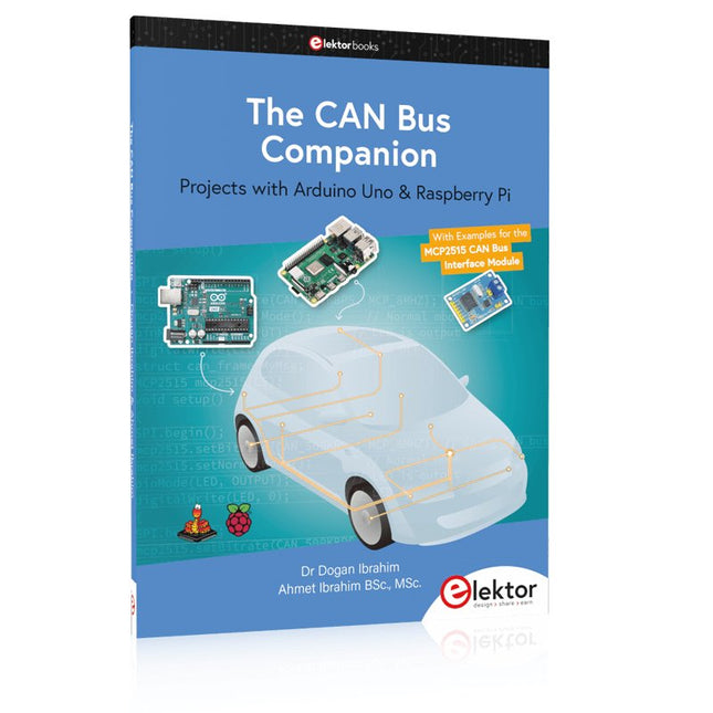
Elektor Publishing The CAN Bus Companion
This book details the use of the Arduino Uno and the Raspberry Pi 4 in practical CAN bus based projects. Using either the Arduino Uno or the Raspberry Pi with off-the-shelf CAN bus interface modules considerably ease developing, debugging, and testing CAN bus based projects. This book is written for students, practicing engineers, enthusiasts, and for everyone else wanting to learn more about the CAN bus and its applications. The book assumes that the reader has some knowledge of basic electronics. Knowledge of the C and Python programming languages and programming the Arduino Uno using its IDE and Raspberry Pi will be useful, especially if the reader intends to develop microcontroller-based projects using the CAN bus. The book should be a useful source of reference material for anyone interested in finding answers to questions such as: What bus systems are available for the automotive industry? What are the principles of the CAN bus? How can I create a physical CAN bus? What types of frames (or data packets) are available in a CAN bus system? How can errors be detected in a CAN bus system and how dependable is a CAN bus system? What types of CAN bus controllers exist? How do I use the MCP2515 CAN bus controller? How do I create 2-node Arduino Uno-based CAN bus projects? How do I create 3-node Arduino Uno-based CAN bus projects? How do I set the acceptance masks and acceptance filters? How do I analyze data on the CAN bus? How do I create 2-node Raspberry Pi-based CAN bus projects? How do I create 3-node Raspberry Pi-based CAN bus projects?
€ 39,95
Members: € 35,96


