
Search results for "elektor or us or style or siren or kit"
-
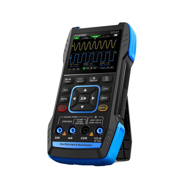
FNIRSI FNIRSI 2C53T (3-in-1) 2-ch Oscilloscope (50 MHz) + Multimeter + Signal Generator
The FNIRSI 2C53T, an enhanced version of its 10 MHz predecessor, is a compact and versatile 3-in-1 device. It combines a dual-channel 50 MHz oscilloscope, a 4.5-digit True RMS multimeter, and a signal generator with 13 waveform types, making it an essential tool for maintenance and research professionals. Oscilloscope: Features 50 MHz bandwidth, 250 MS/s sampling rate, ±400 V protection, FPGA + ARM + ADC architecture, and waveform saving for analysis. Multimeter: 4.5-digit True RMS with 19999 counts, supports AC/DC voltage, current, capacitance, resistance, diode, and continuity measurements. Signal Generator: Outputs 13 signal types up to 50 KHz, with adjustable frequency, amplitude, and duty cycle. With a 2.8-inch LCD, 3000 mAh battery (6-hour runtime), and a portable design, it delivers powerful functionality in a user-friendly package. Specifications Oscilloscope Channels 2 Analog Bandwidth 50 MHz Real-time Sampling Rate 250 MS/s Storage Depth 1 Kpts Impedance 1 MΩ Time Base Range 10ns-20s Vertical Sensitivity 10 mV/div-10 V/div (x1) Maximum Measured Voltage ±400 V Trigger Mode Auto/Normal/Single Trigger Type Rising edge, Falling edge Display Mode Y-T/Rolling/X-Y Coupling Method AC/DC Persistence OFF, 500ms, 1s, ∞ Math 8 Basic Operations + FFT Supported Waveform Screenshot Save, Export Waveform Image, Cursor Measurement, Infinite Afterglow Multimeter DC Voltage 1.9999V/19.999V/199.99V/1000V ±(0.5%+3) AC Voltage 1.9999V/19.999V/199.99V/750.0V ±(1%+3) DC Current 19.999mA/199.99mA/1.9999A/9.999A ±(1.2%+3) AC Current 19.999mA/199.99mA/1.9999A/9.999A ±(1.5%+3) Resistance 19.999MΩ/1.9999MΩ/199.99KΩ/19.999KΩ ±(0.5%+3) 1.9999KΩ/199.99Ω ±(2.0%+3) Capacitance 999.9uF/99.99uF/9.999uF/999.9nF/99.99nF/9.999nF ±(2.0%+5) 9.999mF/99.99mF ±(5.0%+20) Temperature −55~1300°C (−67~2372°F) ±(2.5%+5) Continuity Test Yes Diode Yes Signal Generator 13 Signal Waveforms Sine wave, rectangular wave, sawtooth wave, half wave, full wave, positive step wave, reverse step wave, exponential rise, exponential fall, DC, multi-audio, Sinker pulse, Lorentz wave Output Frequency 0-50 KHz Output Amplitude 0-3 V Output Duty Cycle 0-100% General Display 2.8" HD color screen Resolution 320 x 240 Charging USB-C (5 V/1 A) Battery 3000 mAh Lithium battery Standby Time 6 hours Languages English, Chinese Dimensions 167 x 89 x 35 mm Weight 300 g Differences New vs Old Version Model 2C53T Upgrade 2C53T Predecessor Bandwidth 50 MHz 10 MHz Display Mode Y-T/Rolling/X-Y Y-T/Rolling Math 8 Basic Operations + FFT N/A Cursor Function Yes N/A XY Lissau Graph Yes N/A Afterglow Function Yes N/A Multimeter Accuracy 19999 Counts 9999 Counts Signal Generator 50 KHz 2 MHz Included 1x FNIRSI 2C53T Oscilloscope (50 MHz) 2x P6100 Oscilloscope probes (10X) 1x Multimeter probe 1x Alligator clip probe 1x USB-C charging cable 1x Storage bag 1x Manual Downloads Manual Firmware V1.2.0
-
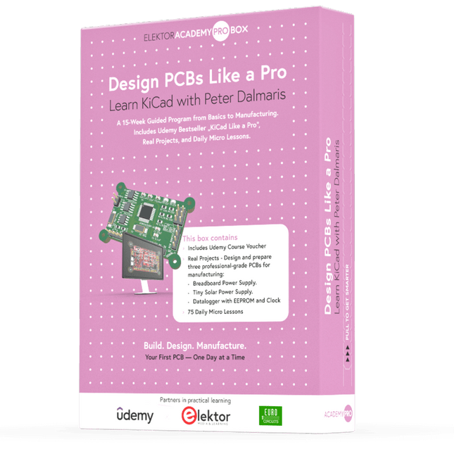
Elektor Academy Pro Design PCBs Like a Pro
Learn KiCad with Peter Dalmaris The Academy Pro Box "Design PCBs like a Pro" offers a complete, structured training programme in PCB design, combining online learning with practical application. Based on Peter Dalmaris’ KiCad course, the 15-week programme integrates video lessons, printed materials (2 books), and hands-on projects to ensure participants not only understand the theory but also develop the skills to apply it in practice. Unlike standard courses, the Academy Pro Box provides a guided learning path with weekly milestones and physical components to design, test, and produce working PCBs. This approach supports a deeper learning experience and better knowledge retention. The box is ideal for engineers, students, and professionals who want to develop practical PCB design expertise using open-source tools. With the added option to have their final project manufactured, participants complete the programme with real results – ready for use, testing, or further development. Learn by doing Build skills. Design real boards. Generate Gerbers. Place your first order. This isn’t just a course – it’s a complete project journey from idea to product. You’ll walk away with: Working knowledge of KiCad’s tools Confidence designing your own PCBs A fully manufacturable circuit board – made by you What's inside the Box (Course)? Both volumes of "KiCad Like a Pro" (valued at €105) Vol 1: Fundamentals and Projects Vol 2: Advanced Projects and Recipes Coupon code to join the bestselling KiCad 9 online course by Peter Dalmaris on Udemy, featuring 20+ hours of video training. You'll complete three full design projects: Breadboard Power Supply Tiny Solar Power Supply Datalogger with EEPROM and Clock Voucher from Eurocircuits for the production of PCBs (worth €85 excl. VAT) Learning Material (of this Box/Course) 15-Week Learning Program ▶ Click here to open Week 1: Setup, Fundamentals, and First Steps in PCB Design Week 2: Starting Your First PCB Project – Schematic Capture Week 3: PCB Layout – From Netlist to Board Design Week 4: Design Principles, Libraries, and Workflow Week 5: Your First Real-World PCB Project Week 6: Custom Libraries – Symbols, Footprints, and Workflow Week 7: Advanced Tools – Net Classes, Rules, Zones, Routing Week 8: Manufacturing Files, BOMs, and PCB Ordering Week 9: Advanced Finishing Techniques – Graphics, Refinement, and Production Quality Week 10: Tiny Solar Power Supply – From Schematic to Layout Week 11: Tiny Solar Power Supply – PCB Layout and Production Prep Week 12: ESP32 Clone Project – Schematic Design and Layout Prep Week 13: ESP32 Clone – PCB Layout and Manufacturing Prep Week 14: Final Improvements and Advanced Features Week 15: Productivity Tools, Simulation, and Automation KiCad Course with 18 Lessons on Udemy (by Peter Dalmaris) ▶ Click here to open Introduction Getting started with PCB design Getting started with KiCad Project: A hands-on tour of KiCad (Schematic Design) Project: A hands-on tour of KiCad (Layout) Design principles and PCB terms Design workflow and considerations Fundamental KiCad how-to: Symbols and Eeschema Fundamental KiCad how-to: Footprints and Pcbnew Project: Design a simple breadboard power supply PCB Project: Tiny Solar Power Supply Project: MCU datalogger with build-in 512K EEPROM and clock Recipes KiCad 9 new features and improvements Legacy (from previous versions of KiCad) KiCad 7 update (Legacy) (Legacy) Gettings started with KiCad Bonus lecture About the Author Dr. Peter Dalmaris, PhD is an educator, an electrical engineer and Maker. Creator of online video courses on DIY electronics and author of several technical books. As a Chief Tech Explorer since 2013 at Tech Explorations, the company he founded in Sydney, Australia, Peter's mission is to explore technology and help educate the world. What is Elektor Academy Pro? Elektor Academy Pro delivers specialized learning solutions designed for professionals, engineering teams, and technical experts in the electronics and embedded systems industry. It enables individuals and organizations to expand their practical knowledge, enhance their skills, and stay ahead of the curve through high-quality resources and hands-on training tools. From real-world projects and expert-led courses to in-depth technical insights, Elektor empowers engineers to tackle today’s electronics and embedded systems challenges. Our educational offerings include Academy Books, Pro Boxes, Webinars, Conferences, and industry-focused B2B magazines – all created with professional development in mind. Whether you're an engineer, R&D specialist, or technical decision-maker, Elektor Academy Pro bridges the gap between theory and practice, helping you master emerging technologies and drive innovation within your organization.
-

Elektor Janvier/Février 2025 (FR)
Le téléchargement intégral de ce numéro est disponible pour nos membres GOLD et GREEN sur le site Elektor Magazine ! Pas encore membre ? Cliquez ici. stockage de l’énergieRéalisez votre propre stockage d’énergie pour réseau de panneaux photovoltaïques simulateur de panneau solaireUne solution pour tester et optimiser les trackers MPP et les onduleurs le concours STM32 Edge AIDécouvrez le STM32N6 et gagnez les 5000 € du concours ! Matériaux à large bande interditePourquoi y a-t-il un tel intérêt pour le SiC et le GaN ? batterie externe pour ordinateur portableProlongez la durée de vie de votre vieil ordinateur portable robots médicauxSurmonter les obstacles techniques et réglementaires prévention du gel pour les vergersavec enregistrement des températures The Analog ThingL'Arduino de l’ordinateur analogique ? commande de relais à faible consommation d'énergieÉconomiser 90% de la puissance de commande amélioration de la charge DC ET5410A+pour un meilleur refroidissement et moins de bruit electronica 2024 : rétrospective compatibilité électromagnétiqueLa CEM en quelques mots ! démarrer en électronique......Filtres actifs réduisez les pertes des chutes de tension avec des condensateursprofitez astucieusement de la réactance capacitive le MCP4725 : un convertisseur numérique-analogique 12 bits pas cheravec une fonction EEPROM pour un comportement sûr au démarrage la pince de test intelligente Fnirsi LCR-ST1 pour CMS labo de test et de mesure personnel basé sur Raspberry PiPour commencer : l'ADC une charge électroniqueUn projet prêt à l'emploi 2025 : l'odyssée de l'IAQuelques projets pour le nouvel an AmpVolt v2.0 : mise à jour100 A et plus ! projet 2.0Corrections, mises à jour et courrier des lecteurs transparence éthiqueCe que révèle l’enquête réalisée par Ethics in Electronics carte Elektor Audio DSP FX Processor (2)Création d'applications
€ 15,50
-
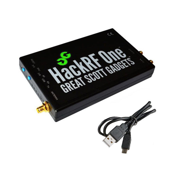
Great Scott Gadgets Great Scott Gadgets HackRF One SDR (1 MHz – 6 GHz)
New Version available! Click here! HackRF One is a Software Defined Radio (SDR) peripheral capable of transmission or reception of radio signals from 1 MHz to 6 GHz. Designed to enable test and development of modern and next generation radio technologies, HackRF One is an open source hardware platform that can be used as a USB peripheral or programmed for stand-alone operation. Specifications 1 MHz to 6 GHz operating frequency Half-duplex transceiver Up to 20 million samples per second 8-bit quadrature samples (8-bit I and 8-bit Q) Compatible with GNU Radio, SDR and more Software-configurable RX and TX gain and baseband filter Software-controlled antenna port power (50 mA at 3.3 V) SMA female antenna connector SMA female clock input and output for synchronization Convenient buttons for programming Internal pin headers for expansion Hi-Speed USB 2.0 USB-powered Open source hardware HackRF One is test equipment for RF systems. It has not been tested for compliance with regulations governing transmission of radio signals. You are responsible for using your HackRF One legally. Included 1x HackRF One SDR 1x Plastic enclosure 1x micro-USB cable Note: An antenna is not included. ANT500 is recommended as a starter antenna for HackRF One. Downloads Documentation GitHub Source code and hardware design files
-

SunFounder SunFounder Kepler Kit (Ultimate Starter Kit for Raspberry Pi Pico W)
Your gateway to IoT and microcontroller programming With 450+ components and 117 online projects, this comprehensive kit ignites your creativity. The tutorials by Paul McWhorter make learning enjoyable for beginners and advanced users. This kit supports MicroPython, C/C++, and Piper Make, offering diverse programming options. Explore sensors, actuators, LEDs, and LCDs for endless project possibilities. From home automation to robotics, this kit empowers your tech journey. Features IoT Starter Kit for Beginners: This kit offers a rich IoT learning experience for beginners. With 450+ components, 117 projects, and expert-led video lessons, this kit makes learning microcontroller programming and IoT engaging and accessible. Expert-Guided Video Lessons: The kit includes 27 video tutorials by the renowned educator, Paul McWhorter. His engaging style simplifies complex concepts, ensuring an effective learning experience in microcontroller programming. Wide Range of Hardware: The kit includes a diverse array of components like sensors, actuators, LEDs, LCDs, and more, enabling you to experiment and create a variety of projects with the Raspberry Pi Pico W. Supports Multiple Languages: The kit offers versatility with support for three programming languages - MicroPython, C/C++, and Piper Make, providing a diverse programming learning experience. Dedicated Support: Benefit from our ongoing assistance, including a community forum and timely technical help for a seamless learning experience. Included Raspberry Pi Pico W Breadboard Jumper Wires Resistor Transistor Capacitor Diode Li-po Charger Module 74HC595 TA6586 – Motor Driver Chip LED RGB LED LED Bar Graph 7-segment Display 4-Digit 7-Segment Display LED Dot Matrix I²C LCD1602 WS2812 RGB 8 LEDs Strip Buzzer DC Motor Servo DC Water Pump Relay Button Micro Switch Slide Switch Potentiometer Infrared Receiver Joystick Module 4x4 Keypad MPR121 Module MFRC522 Module Photoresistor Thermistor Tilt Switch Reed Switch PIR Motion Sensor Module Water Level Sensor Module Ultrasonic Module DHT11 Humiture Sensor MPU6050 Module Documentation Online Tutorials in 3 languages (EN, DE and JP)
-

NXP Semiconductors NXP FRDM-MCXN947 Development Board
The FRDM-MCXN947 is a compact and versatile development board designed for rapid prototyping with MCX N94 and N54 microcontrollers. It features industry-standard headers for easy access to the MCU's I/Os, integrated open-standard serial interfaces, external flash memory, and an onboard MCU-Link debugger. Specifications Microcontroller MCX-N947 Dual Arm Cortex-M33 cores @ 150 MHz each with optimized performance efficiency, up to 2 MB dual-bank flash with optional full ECC RAM, External flash Accelerators: Neural Processing Unit, PowerQuad, Smart DMA, etc. Memory Expansion *DNP Micro SD card socket Connectivity Ethernet Phy and connector HS USB-C connectors SPI/I²C/UART connector (PMOD/mikroBUS, DNP) WiFi connector (PMOD/mikroBUS, DNP) CAN-FD transceiver Debug On-board MCU-Link debugger with CMSIS-DAP JTAG/SWD connector Sensor P3T1755 I³C/I²C Temp Sensor, Touch Pad Expansion Options Arduino Header (with FRDM expansion rows) FRDM Header FlexIO/LCD Header SmartDMA/Camera Header Pmod *DNP mikroBUS User Interface RGB user LED, plus Reset, ISP, Wakeup buttons Included 1x FRDM-MCXN947 Development Board 1x USB-C Cable 1x Quick Start Guide Downloads Datasheet Block diagram
-
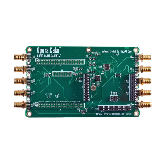
Great Scott Gadgets Great Scott Gadgets Opera Cake (Antenna Switch for HackRF SDR)
Opera Cake is an antenna switching add-on board for HackRF One/Pro that is configured with command-line software either manually, or for automated port switching based on frequency or time. It has two primary ports, each connected to any of eight secondary ports, and is optimized for use as a pair of 1x4 switches or as a single 1x8 switch. Its recommended frequency range is 1 MHz to 4 GHz. When HackRF One/Pro is used to transmit, Opera Cake can automatically route its output to the appropriate transmit antennas, as well as any external filters, amplifiers, etc. No changes are needed to the existing SDR software, but full control from the host is available. Opera Cake also enhances the HackRF One/Pro’s use as a spectrum analyzer across its entire operating frequency range of 1 MHz to 4 GHz. Antenna switching works with the existing hackrf_sweep feature, which can sweep the whole tuning range in less than a second. Automatic switching mid-sweep enables the use of multiple antennas when sweeping a wide frequency range. Downloads Documentation GitHub


