
Search results for "elektor or uno or r4"
-

Elektor Digital H0W2: Get Started with the SensorTile.box (E-book)
STmicroelectronics’ wireless IoT & wearable sensor development kit ‘SensorTile.box’ is a portable multi-sensor circuit board housed in a plastic box and developed by STMicroelectronics. It is equipped with a high-performance 32-bit ARM Cortex-M4 processor with DSP and FPU, and various sensor modules, such as accelerometer, gyroscope, temperature sensor, humidity sensor, atmospheric pressure sensor, microphone, and so on. SensorTile.box is ready to use with wireless IoT and Bluetooth connectivity that can easily be used with an iOS or Android compatible smartphone, regardless of the level of expertise of the users. SensorTile.box is shipped with a long-life battery and all the user has to do is connect the battery to the circuit to start using the box. The SensorTile.box can be operated in three modes: Basic mode, Expert mode, and Pro mode. Basic mode is the easiest way of using the box since it is pre-loaded with demo apps and all the user has to do is choose the required apps and display or plot the measured data on a smartphone using an app called STE BLE Sensor. In Expert mode users can develop simple apps using a graphical wizard provided with the STE BLE Sensor. Pro mode is the most complex mode allowing users to develop programs and upload them to the SensorTile.box. This book is an introduction to the SensorTile.box and includes the following: Brief specifications of the SensorTile.box; description of how to install the STE BLE Sensor app on an iOS or Android compatible smartphone required to communicate with the box. Operation of the SensorTile.box in Basic mode is described in detail by going through all of the pre-loaded demo apps, explaining how to run these apps through a smartphone. An introduction to the Expert mode with many example apps developed and explained in detail enabling users to develop their own apps in this mode. Again, the STE BLE Sensor app is used on the smartphone to communicate with the SensorTile.box and to run the developed apps. The book then describes in detail how to upload the sensor data to the cloud. This is an important topic since it allows the sensor measurements to be accessed from anywhere with an Internet connection, at any time. Finally, Pro mode is described in detail where more experienced people can use the SensorTile.box to develop, debug, and test their own apps using the STM32 open development environment (STM32 ODE). The Chapter explains how to upload the developed firmware to the SensorTile.box using several methods. Additionally, the installation and use of the Unicleo-GUI package is described with reference to the SensorTile.box. This PC software package enables all of the SensorTile.box sensor measurements to be displayed or plotted in real time on the PC.
€ 29,95
Members: € 26,96
-
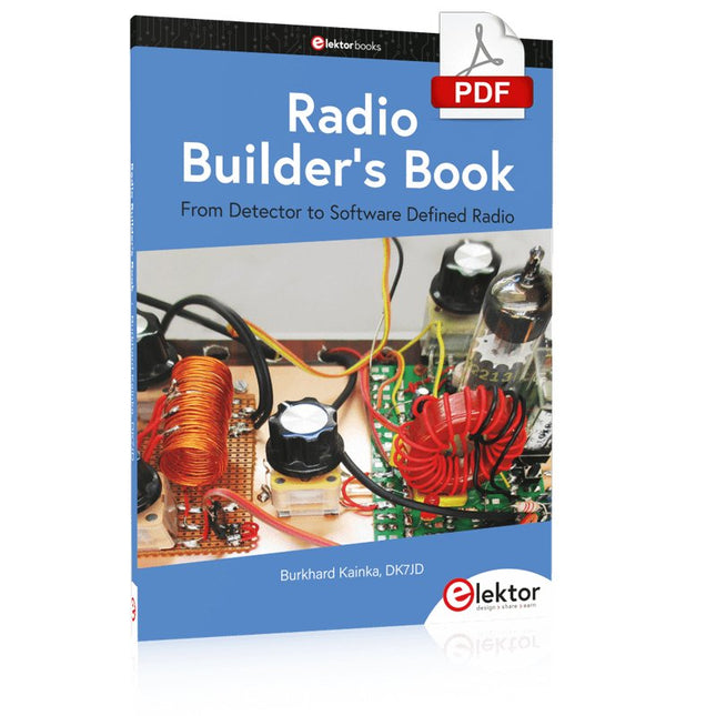
Elektor Digital Radio Builder's Book (PDF)
From Detector to Software Defined RadioRadio frequency (RF) technology is one of the areas which still allows putting your own ideas into practice. Countless circuit variants with special objectives allow space for meaningful experiments and projects. Many things simply aren’t available off the shelf. Crystal detector radios without their own power source, simple tube receivers with a touch of nostalgia, the first reception attempts at Software Defined Radio, special receivers for amateur radio, all this can be realized with little effort and as a perfect introduction to RF electronics.For a long time, radio construction was the first step into electronics. Meanwhile, there are other ways, especially via computers, microcontrollers, and digital technology. However, the analog roots of electronics are often neglected. Elementary radio technology and easy-to-do experiments are particularly well suited as a learning field for electronics because you can start with the simplest basics here.But the connection to modern digital technology is also obvious, for example, when it comes to modern tuning methods such as PLL and DDS or modern DSP radios.This book aims to give an overview and present a collection of simple RF projects. The author would like to support you to develop your own ideas, to design your own receivers and to test them.
€ 32,95
Members: € 29,66
-

Raspberry Pi Foundation Das offizielle Raspberry Pi-Handbuch für Einsteiger (5. Auflage)
Vollständig aktualisiert für Raspberry Pi 5 Raspberry Pi ist ein kleiner, cleverer, in Großbritannien hergestellter Computer, der voller Potenzial steckt. Der Raspberry Pi basiert auf einem energieeffizienten Prozessor der Desktop-Klasse und soll Ihnen dabei helfen, das Programmieren zu erlernen, herauszufinden, wie Computer funktionieren, und Ihre eigenen erstaunlichen Dinge zu bauen. Dieses Buch wurde geschrieben, um Ihnen zu zeigen, wie einfach der Einstieg ist. Lernen Sie, wie Sie: Richten Sie Ihren Raspberry Pi ein, installieren Sie sein Betriebssystem und beginnen Sie mit der Nutzung dieses voll funktionsfähigen Computers. Starten Sie Codierungsprojekte mit Schritt-für-Schritt-Anleitungen für die Programmiersprachen Scratch 3, Python und MicroPython. Experimentieren Sie mit der Verbindung elektronischer Komponenten und haben Sie Spaß beim Erstellen erstaunlicher Projekte. Neu in der 5. Auflage: Aktualisiert für die neuesten Raspberry Pi-Computer: Raspberry Pi 5 und Raspberry Pi Zero 2 W. Deckt das neueste Raspberry Pi OS ab. Enthält ein neues Kapitel über den Raspberry Pi Pico. Downloads GitHub
€ 24,95€ 9,98Best Price
-

Elektor Digital PIC-Mikrocontroller (E-book)
PIC-Mikrocontroller (E-book)
€ 44,80
Members: € 40,32
-
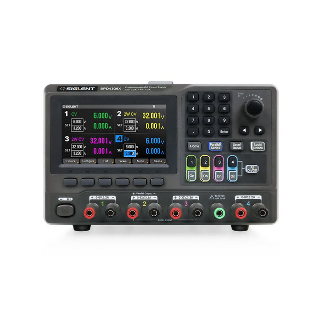
Siglent Siglent SPD4306X 4-ch DC Power Supply (400 W)
The Siglent SPD4306X is a 4-channel DC Linear Programmable Power Supply equipped with a 4.3-inch TFT-LCD display, friendly human-machine interface, and excellent performance indicators. Real-time waveform display provides engineers with an informative user interface. SPD4306X offers a total output power of 400 W with a resolution of 1 mV/1 mA. The maximum voltage and current for each channel are as follows: CH1: 15 V/1.5 A CH2: 30 V/6 A CH3: 30 V/6 A CH4: 15 V/1 A Features Rated output power: 400 W Rated voltage: 32 V, 12 V, 30 V Up to four high-precision power supplies with independent controllable outputs, supporting CH2 and CH3 series and parallel connections Clear graphical interface with waveform and timer display modes 5-digit voltage and current display with minimum resolution of 1 mV, 1 mA Fast output response time: <50us The high current channel support remote voltage compensation sense function. The maximum compensation voltage is 0.6 V Overvoltage protection and overcurrent protection or safe and accurate operation Equipped with a 4.3-inch TFT-LCD display (480 x 272 resolution) USB and LAN standard communication USB-GPIB module is optional Excellent channel density with up to 4 channels in a 3U half rack package Internal data storage for setups and parameters Embedded Web Server with instrument communication that doesn’t require software installation Fully SCPI programming command set support as well as a LabView driver for remote control and system automation Specifications SPD4323X SPD4121X SPD4306X Channel Output CH1: Voltage 0 to 6 V Current 0 to 3.2 ACH2: Voltage 0 to 32 V Current 0 to 3.2 ACH3: Voltage 0 to 32 V Current 0 to 3.2 ACH4: Voltage 0 to 6 V Current 0 to 3.2 A CH1: Voltage 0 to 15 V Current 0 to 1.5 ACH2: Voltage 0 to 12 V Current 0 to 10 ACH3: Voltage 0 to 12 V Current 0 to 10 ACH4: Voltage 0 to 15 V Current 0 to 1.5 A CH1: Voltage 0 to 15 V Current 0 to 1.5 ACH2: Voltage 0 to 30 V Current 0 to 6 ACH3: Voltage 0 to 30 V Current 0 to 6 ACH4: Voltage 0 to 15 V Current 0 to 1 A Resolution 1 mV, 1 mA 1 mV, 1 mA 1 mV, 1 mA Setting Accuracy Voltage: ±(0.03% of reading+10) mV, Current: ±(0.3% of reading+10) mA Voltage: ±(0.03% of reading+10) mV, Current: ±(0.3% of reading+10) mA Voltage: ±(0.03% of reading+10) mV, Current: ±(0.3% of reading+10) mA Readback Accuracy Voltage: ±(0.03% of reading+10) mV, Current: ±(0.3% of reading+10) mA Voltage: ±(0.03% of reading+10) mV, Current: ±(0.3% of reading+10) mA Voltage: ±(0.03% of reading+10) mV, Current: ±(0.3% of reading+10) mA Display 4.3" TFT-LCD 5-digit voltage and current display 4.3" TFT-LCD 5-digit voltage and current display 4.3" TFT-LCD 5-digit voltage and current display Output power 240 W 285 W 400 W Included 1x Siglent SPD4306X Power Supply 1x Power cord (EU) 1x Output test cord (3 A) 1x USB cable 1x Quick start guide Downloads Datasheet Manual Quick start
€ 1.101,10
-

JOY-iT Joy-Pi Note 2 (incl. Raspberry Pi 5, 8 GB)
The Joy-Pi Note 2 is a portable, all-in-one electronics experimentation and learning platform, fully compatible with the Raspberry Pi 4 and 5. Combining an 11.6-inch IPS display, a detachable wireless keyboard, and a compact, robust housing, it provides a flexible environment for electronics development, programming, and education. With more than 45 hands-on courses and projects, the Joy-Pi Note 2 supports learning and experimentation with Python, Scratch, robotics, and IoT applications. Its integrated learning platform provides step-by-step instructions, making it suitable for beginners, students, educators, and experienced makers. The system features over 22 integrated sensors and modules, including temperature, light, motion, and distance sensors, as well as LED displays and motor interfaces. Additional connectivity options, including USB-C and GPIO expansion interfaces, allow users to develop and test their own projects. With support for the Raspberry Pi 5, the Joy-Pi Note 2 also benefits from improved processing power and graphics performance, making it a versatile platform for electronics education, prototyping, and advanced experimentation. Features Complete Electronics Experimentation Kit All-in-One Learning and Experimentation Platform Compatible with Raspberry Pi 4 & 5 Pre-installed Interactive Learning Platform Detachable Wireless Keyboard Integrated Storage Compartment for Power Bank and Accessories Specifications Display 11.6" LCD Display Camera 2 MP Learning platform 45+ courses & projects Displays 7-segment display, 16x2 display, 1.8" TFT display, 0.96" OLED display, 8x8 RGB matrix Power supply 5 V/5 A, USB-C Displays 7-segment display, 16x2 LCD module, 8x8 RGB matrix Sensors DHT temperature & humidity sensor, tilt sensor, motion sensor, sound sensor, touch sensor, RFID module, light sensor, ultrasonic sensor Motors Servo interface, stepper motor interface, vibration motor Control system Joystick, 4x4 button matrix, Raspberry Pi & PCV connection switch, motion sensor sensitivity controller, sound sensor sensitivity controller, 16x2 LCD module brightness controller Miscellaneous Relay, fan, GPIO extension, GPIO LED indicator, breadboard, IO/ ADC/I²C/UART extension interface, infrared sensor interface, buzzer, display driver Accessories RFID chip, RFID card, power supply unit, servo motor, stepper motor, infrared receiver, infrared remote control, DC motor with fan attachment, screwdriver, microSD card (32 GB), SD card reader, electronic accessories, wireless mouse, wireless keyboard Dimensions 291 x 190 x 46 mm Weight 1.3 kg Included Joy-Pi Note 2 Notebook Raspberry Pi 5 (8 GB RAM) Accessories USB-C power supply unit Quick start guide Downloads Joy-Pi website Datasheet
€ 449,00
Best Price
-

Elektor Digital Das 1-Wire-Praxisbuch (PDF)
1-Wire ist die Bezeichnung für eine serielle Schnittstelle, die mit nur einer Datenader auskommt. Es ist ein Master-Multi-Slave-Kommunikationsprotokoll. Verfügbar sind integrierte Bausteine zur Temperaturmessung, Akkuüberwachung, Echtzeituhr und beispielsweise Hotelschließanlagen. Eine Besonderheit von 1-Wire-Geräten ist die Spannungsversorgung aus der Gegenstation, hierbei erfolgt die Versorgung der Slaves über die Datenleitung. Der Leser erhält mit „Das 1-Wire-Praxisbuch“ eine umfassende Einführung in die 1-Wire-Technologie. Das Buch zeigt anhand praktischer Projekte zum Nachbauen, wie man verschiedene verfügbare 1-Wire-Chips in eigene Mikrocontroller-gesteuerte Anwendungen integrieren kann, und zwar mit Assembler-Software-Implementierungen für PIC-Mikrocontroller und mit Sketches für den Arduino. Die 1-Wire-Technik kommt in dem Buch praxisnah bei einem elektronischen Schloss zum Einsatz, das von einem PIC-Mikrocontroller gesteuert wird. Ein weiteres Praxisprojekt erläutert Schritt für Schritt, wie beispielsweise eine ständige Temperaturmessung mit 1-Wire-Bausteinen möglich ist.
€ 32,80
Members: € 29,52
-

OWON OWON ADS914A 4-ch Oscilloscope (125 MHz)
The OWON ADS900A series is a compact 12-bit digital oscilloscope offering up to 2 GSa/s, 100 Mpts memory, and 125/250 MHz bandwidth. With its 7" multi-touch display, FFT, protocol decoding, and integrated logic analyzer, it delivers precise signal analysis for lab, workshop, and field applications. Specifications ADS914A ADS924A Bandwidth (-3 dB) 125 MHz 250 MHz Channels 4 Max. sample rate 2 GSa/s (single-channel) 1 GSa/s (dual-channel) 500 MSa/s (full-channel) DC Gain Accuracy 3% (≤1 mV) 2% (≥2 mV) Max memory depth 100M Vertical resolution 12 bits Relay time accuracy ±25 ppm (typical) Input Impedance 1 MΩ±2%, parallel with20 pF±5 pF Probe Attenuation Coefficient 1.00μX-1M.00X,step by 1-2-5, support custom Trigger type Edge, Video, Pulse, Slope, Runt, Windows, Timeout, Nth, Logic, RS232/UART, I²C, SPI CAN, LIN Bus decoding RS232/UART, I²C, SPI, CAN, LIN Auto measurement Period, Frequency, +Width, -Width, Rise Time, Fall Time, Scr Duty, +Duty,-Duty, Vavg, Vpp, VRMS, Overshoot, Vmax, Vmin, Vtop, CycRms, Vbase, Vamp, Preshoot, Std Dev, +Pulse Cnt, -Pulse Cnt, Rise Cnt, Fall Cnt, Area, Cyc Area, Delay(A↑-B↑), Delay(A↑-B↓), Delay(A↓-B↑), Delay(A↓-B↓), Phase(A↑-B↑) Phase(A↑-B↓), Phase(A↓-B↑), Phase(A↓-B↓), FRR(A↑-B↑), FRF(A↑-B↓) FFR(A↓-B↑), FFF(A↓-B↓), LRR(A↑-B↑), LRF(A↑-B↓), LFR(A↓-B↑), LFF(A↓-B↓) Waveform Math +, -, *, /, &&, ||, ^, !, Intg, Diff, Sqrt, Function operation (Lg / Ln / Exp / Abs / Sine / Cosine / Tan), FFT, FFT rms, User Defined, digital filter (low pass, high pass, band pass, band reject) Frequency counter 6-digit frequency counter Maximum frequency: maximum analog bandwidth of oscilloscope Voltmeter Support DC, AC+DCrms, ACrms, Resolution: 4 digits (ACV/DCV) Logical Analyzer Specifications Number of channels 16 input channels (D0-D15) (D0 to D7, D8 to D15) Max. input voltage ±40V peak CAT I, transient overvoltage 800Vpk Input Impedance 100kΩ, 8 pF Vertical resolution 1 bit Other Communication Interface HDMI, USB device, USB Host, Trig Out (P/F), LAN Display 7 inch (1024x600), capacitive multi-touch screen Power supply interface USB-C Dimensions 260 x 160 x 78 mm Weight 1.5 kg Included 1x OWON ADS914A Oscilloscope 1x Power Adapter 1x Power Cord 1x USB Cable 1x Probe 1x Quick Guide Downloads Manual Quick Guide PC Software
€ 579,59
-

FNIRSI FNIRSI HRM-10 Battery Internal Resistance & Voltage Tester
The FNIRSI HRM-10 is a portable, high-precision battery internal resistance and voltage tester. This device offers true four-wire measurement and is designed for both accuracy and ease of use. It automatically measures internal resistance and voltage values simultaneously, displaying the results on its HD color screen. Users have the option to manually adjust voltage and resistance ranges to suit their needs. The device also includes a sorting mode that automatically filters the good and bad batteries based on user-set thresholds. Additionally, it supports the storage of historical data and allows for exporting measurement records in table format. Features High Measurement Accuracy Tabular Data Export Auto-Evaluate Measurement Results 8 Threshold Settings HD Color Screen Folding Stand 1000 mAh Lithium Battery Specifications Voltage Resistance Measuring range 0-100 V (DC) 0-200 Ω Accuracy ±0.5% ±0.5% Gear Automatic, 1 V, 10 V, 100 V Automatic, 20 mΩ, 200 mΩ, 2 Ω, 20 Ω, 200 Ω Instrument test signal frequency 1 Khz (AC) Rechargeable USB-C (5 V/1 A) Built-in battery 1000 mAh lithium battery User calibration Yes Sorting mode Yes History record Yes Recorded data export Yes Working environment –10°C to +45°C, relative humidity <80% Storage environment –20°C to +80°C, relative humidity <80% Dimensions 158.7 x 80.5 x 28.4 mm Weight 225 g Included 1x FNIRSI HRM-10 Internal Resistance Tester 1x Clip Test Line 1x USB-C data cable 1x Manual Downloads Manual Firmware V0.3
€ 49,95
-

Elektor Publishing Grundlagen der Elektrotechnik
Dieses Fachbuch führt Studenten, Schüler und Selbststudierende in die wichtigsten Grundlagen der Elektrotechnik ein. Es werden die Gebiete der Gleichstromtechnik, des elektrischen und magnetischen Feldes sowie der Wechselstromtechnik, des Kondensators und der Spulen in einem Band zusammenhängend und übersichtlich dargestellt. Daran schließt sich die Beschreibung des elektrischen und magnetischen Feldes an. Zur Erzielung einer optimalen Verständlichkeit erfolgt die Darbietung des Stoffes nach dem Grundsatz, den Leser von einfachen Sachverhalten schrittweise zu komplexeren Problemstellungen zu führen. Zusätzlich sind den einzelnen Abschnitten Aufgaben mit ausführlichen Lösungswegen zugeordnet. Sie sind zum Erfassen der Gedankengänge von besonderer Bedeutung. Das Buch ist in acht Kapiteln unterteilt: Physikalische Größen und ihre Einheiten Elektrotechnische Größen im Gleichstromkreis Einfacher Stromkreis Erweiterter Strombereich Messgeräte für die Grundschaltungen der Elektronik Kondensator Spulen, Transformatoren, Relais und Lautsprecher Zusammengesetzte Wechselstromkreise Die Aufgaben sind zum großen Teil der elektrotechnischen Praxis entnommen und werden mit steigendem Schwierigkeitsgrad angeboten, so dass für jede Vorbildungsstufe geeigneter Übungsstoff zu finden ist. Der Inhalt ist als Hilfsmittel für den Unterricht und das Selbststudium bestimmt, sie kann auch dem Praktiker beim Auffrischen seiner Kenntnisse und zur Förderung seiner Rechenfertigkeit nützlich sein. Mit diesem Buch gibt der Autor sein gesamtes Wissen, das er sich im Laufe der Zeit in der Industrie und dem Unterricht an einer Technikerschule angeeignet hat, an den Leser weiter.
€ 39,80
Best Price
-

Elektor Digital Explore ATtiny Microcontrollers using C and Assembly Language (E-book)
AVR Architecture and Programming An in-depth look at the 8-bit AVR architecture found in ATtiny and ATmega microcontrollers, mainly from a software and programming point of view. Explore the AVR architecture using C and assembly language in Microchip Studio (formerly Atmel Studio) with ATtiny microcontrollers. Learn the details of how AVR microcontrollers work internally, including the internal registers and memory map of ATtiny devices. Program ATtiny microcontrollers using an Atmel-ICE programmer/debugger, or use a cheap hobby programmer, or even an Arduino Uno as a programmer. Most code examples can be run using the Microchip Studio AVR simulator. Learn to write programs for ATtiny microcontrollers in assembly language. See how assembly language is converted to machine code instructions by the assembler program. Find out how programs written in the C programming language end up as assembly language and finally as machine code instructions. Use the Microchip Studio debugger in combination with a hardware USB programmer/debugger to test assembly and C language programs, or use the Microchip Studio AVR simulator. DIP packaged ATtiny microcontrollers are used in this volume for easy use on electronic breadboards, targeting mainly the ATtiny13(A) and ATtiny25/45/85. Learn about instruction timing and clocks in AVR microcontrollers using ATtiny devices. Be on your way to becoming an AVR expert with advanced debugging and programming skills.
€ 34,95
Members: € 31,46
-

Elektor Digital Elektronik-Praxis für Einsteiger (E-book)
Elektronik-Praxis für Einsteiger (E-book)
€ 32,80
Members: € 29,52


