
Search results for "avr OR hardware OR en OR c OR programmering OR in OR de OR praktijk"
-

Elektor Digital Elektor September/Oktober 2024 (PDF)
Elektor GREEN en GOLD leden kunnen deze uitgave hier downloaden. Nog geen lid? Klik hier om een lidmaatschap af te sluiten. Autonome sensor-nodeLoRa-gebaseerde datatransmissie, voeding met zonnecellen Elektor eXpansion Board v1.0voor ESP32S3 en andere XIAO-controllerboards Modeltrein met camerainbouw van een ESP32 CAM-module Breedbandige magnetische lange golf-antenneontvang meerdere kanalen zonder afstemmen TensorFlow Lite op kleine microcontrollersvanuit het standpunt van een (absolute) beginner Een hub voor RS-422- en RS-485-apparatende bus is de ster! RF-sondemet LED-staafdiagram Alle begin......bekijkt meer opampschakelingen Open VarioEen Open-Source Multifunctie Variometer voor Paragliden Uit het leven gegrepenover de vanzelfsprekendheid der dingen AI-gebaseerde watermeter-uitlezing (2)koppel uw oude watermeter met het IoT! Slimme landbouwdetectie van ongedierte op basis van machine learning met IoT-connectiviteit Waarom Anybus CompactCom de ideale keuze is voor embedded industriële communicatie Communicatie standaard IQRFBetrouwbaarheid voor draadloze, low-rate Mesh-netwerken met verlies Constructie van een slimme landbouwrobotbelangrijkste technische overwegingen en uitdagingen Audio-notchfilter met instelbare frequentieuniversele oplossing voor het onderdrukken van frequenties in audiotoepassingen Het LeoINAGPS-systeemnuttige informatie over uw elektrische voertuig LoRa-node op zonne-energieeenmodulaire, compacte en veelzijdige IoT-oplossing AWS voor Arduino en co. (2)data versturen met AWS IoT ExpressLink Project 2.0correcties, updates en brieven van lezers 2024: een AI-odysseedesktop- versus embedded accelerators: enkele opties ESP32-bereiksuitbreidingeen eenvoudige antenne-modificatie WoTS 2024World of Industry, Technology & Science biedt oplossingen Metafas @ WoTS 2024Smart thinking in printed electronics Hansamatrix @ WoTS 2024 Value Procurement Centre @ WoTS 2024Omdat niet alles in Nederland kan! PCBWay @ WoTS 2024 GW Instek @ WoTS 2024 Rohde & Schwarz @ WoTS 2024 Unis Group @ WoTS 2024 Eurocircuits @ WoTS 2024Jouw Pad naar Uitmuntendheid in Elektronica Productie
€ 9,95
-
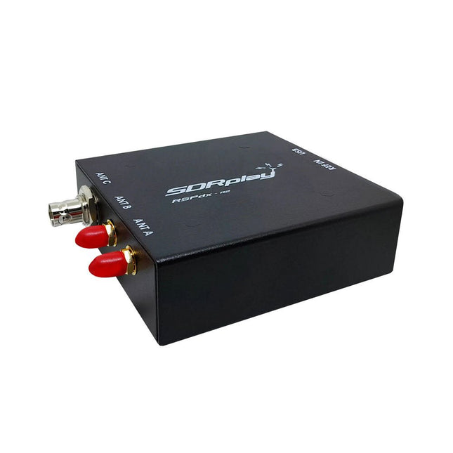
SDRplay SDRplay RSPdx-R2 Single-Tuner 14-bit SDR Receiver (1 kHz to 2 GHz)
The SDRplay RSPdx-R2 is a wideband full featured single-tuner 14-bit SDR receiver which covers the entire RF spectrum from 1 kHz to 2 GHz giving up to 10 MHz of spectrum visibility. It contains three antenna ports, two of which use SMA connectors and operate across the full 1 kHz to 2 GHz range and the third uses a BNC connector which operates up to 200 MHz. The RSPdx-R2 is an enhanced version of the RSPdx with further design improvements for use at frequencies below 2 MHz. Housed in a strong steel case, in addition to the functionality of the RSP1B, the RSPdx-R2 provides three software selectable antenna inputs and an external clock input. It offers excellent performance through HF and VHF frequencies all the way up to 2 GHz. The RSPdx-R2 also supports an "HDR mode" optimised for the demanding radio reception conditions below 2 MHz. The RSPdx-R2, when used in conjunction with SDRplay’s own software, introduces a special HDR (High Dynamic Range) mode for reception within selected bands below 2 MHz. HDR mode delivers improved intermodulation performance and fewer spurious responses for those challenging bands. Features Covers all frequencies from 1 kHz through VLF, LF, MW, HF, VHF, UHF and L-band to 2 GHz, with no gaps Receive, monitor and record up to 10 MHz of spectrum at a time Significantly improved noise performance below 1 MHz (i.e. for some MF, LF and below) Improved dynamic range below 2 MHz both in tuner mode and HDR mode HDR mode below 2 MHz giving overall dynamic range and selectivity advantages Software selectable choice of 3 antenna ports External clock input for synchronisation purposes, or connection to GPS reference clock for extra frequency accuracy Excellent dynamic range for challenging reception conditions Free use of Windows-based SDRuno software (check website for versions supported) Free use of SDRconnect SDR and server software for Windows, MacOS and Linux (Check website for versions supported) Multiplatform driver and API support including Windows, Linux, Mac and Raspberry Pi 4/5 Strong and growing software support network Calibrated S meter/RF power and SNR measurement with SDRuno (including datalogging to .CSV file capability) Documented API provided to allow demodulator or application development on multiple platforms Applications (Amateur) Shortwave radio listening Broadcast DXing (AM/FM/TV) Panadaptor Aircraft (ADS-B and ATC) Slow Scan TV Multi-amateur band monitoring WSPR & digital modes Weather fax (HF and satellite) Satellite monitoring Geostationary environmental satellites Trunked radio Utility and emergency service monitoring Fast and effective antenna comparison Applications (Industrial) Spectrum Analyser Surveillance Wireless microphone monitoring RF surveying IoT receiver chain Signal logging RFI/EMC detection Broadcast integrity monitoring Spectrum monitoring Power measurement Applications (Educational/Scientific) Teaching Receiver design Radio astronomy Passive radar Ionosonde Spectrum analyser Receiver for IoT sensor projects Antenna research Specifications Frequency Range 1 kHz – 2 GHz Antenna Connector SMA Antenna Impedance 50 Ohms Current Consumption (Typical) 190 mA @ >60 MHz (excl. Bias-T)120 mA @ <60 MHz (excl. Bias-T) USB Connector USB-B Maximum Input Power +0 dBm Continuous+10 dBm Short Duration ADC Sample Rates 2-10.66 MSPS ADC Number of Bits 14 bit 2-6.048 MSPS12 bit 6.048-8.064 MSPS10 bit 8.064-9.216 MSPS8 bit >9.216 MSPS Bias-T 4.7 V100 mA guaranteed Reference 0.5ppm 24 MHz TCXOFrequency error trimmable to 0.01ppm in field Operating Temperature −10˚C to +60˚C Dimensions 113 x 94 x 35 mm Weight 315 g Downloads Datasheet Software RSPdx-R2 vs RSPduo RSPdx-R2 RSPduo Continuous coverage from 1 kHz to 2 GHz ✓ ✓ Up to 10 MHz visible bandwidth ✓ ✓ 14-bit ADC silicon technology plus multiple high-performance input filters ✓ ✓ Software selectable AM/FM & DAB broadcast band notch filters ✓ ✓ 4.7 V Bias-T for powering external remote antenna amplifier ✓ ✓ Powers over the USB cable with a simple type B socket ✓ ✓ 50Ω SMA antenna input(s) for 1 kHz to 2 GHz operation (software selectable) 2 2 Additional software selectable Hi-Z input for up to 30 Mhz operation ✓ Additional software selectable 50Ω BNC input for up to 200 MHz operation ✓ Additional LF/VLF filter for below 500 kHz ✓ 24 MHz reference clock input (+ output on RSPduo) ✓ ✓ Dual tuners enabling reception on 2 totally independent 2 MHz ranges ✓ Dual tuners enabling diversity reception using SDRuno ✓ Rugged black painted steel case ✓ ✓ Overall performance below 2 MHz for MW and LF ++ + Multiple simultaneous applications + ++ Performance in challenging fading conditions (*using diversity tuning) + *++
€ 263,00
-

Elektor Publishing LTspice Grundlagen
Eine Einführung in die Schaltungssimulation LTspice wurde von Mike Engelhardt entwickelt und gehört inzwischen zu Analog Devices. Es handelt sich dabei um ein Programm zur Schaltplanerstellung – einen leistungsstarken, schnellen und kostenlosen SPICE-Simulator sowie um ein Werkzeug zur Darstellung von Kurvenverläufen. Es bietet eine umfangreiche Bauteildatenbank, die weltweit durch SPICE-Modelle unterstützt wird. Mit LTspice kann man schnell und einfach Schaltpläne erstellen. Dank der leistungsfähigen grafischen Ausgabefunktionen lassen sich Spannungen und Ströme in einer Schaltung, die Leistungsaufnahme der Bauteile und viele weitere Parameter darstellen. Ziel dieses Buches ist es, den Entwurf und die Simulation elektronischer Schaltungen mit LTspice zu vermitteln. Es behandelt unter anderem folgende Themen: DC und AC-Schaltungen Kleinsignal- und Z-Dioden Transistorschaltungen inkl. Oszillatoren Tryristor-, Diac- und Triacschaltungen Operationsverstärkerschaltungen inkl. Oszillatoren Der 555 Timer-IC Filter Spannungsregler Optokoppler Erstellung von Spannungskurven Simulation von Logikschaltungen mit der 74HC-Familie SPICE-Modellierung LTspice ist ein äußerst vielseitiges Werkzeug zur Simulation elektronischer Schaltungen mit zahlreichen Funktionen und Anwendungsmöglichkeiten. Eine vollständige Behandlung aller Details würde jedoch den Rahmen dieses Buches sprengen. Daher konzentriert sich das Buch auf die gängigsten Themen wie DC- und AC-Analyse, Parametersweep, Übertragungsfunktionen, Oszillatoren, Diagramme und weitere grundlegende Anwendungen. Obwohl es sich um eine Einführung handelt, deckt dieses Buch dennoch die meisten Interessensgebiete all jener ab, die sich mit der Simulation elektronischer Schaltungen beschäftigen.
€ 39,80
Best Price
-
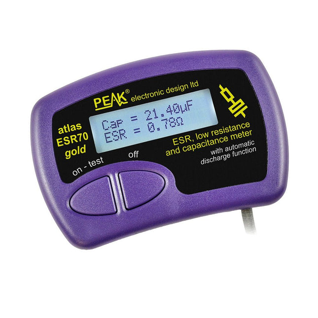
Peak Peak Atlas ESR70 gold (ESR and Capacitance Meter)
The Peak Atlas ESR70 gold is an enhanced version of the previous Peak Atlas ESR70 Plus. It does everything that the ESR70 Plus did but better. It now measures capacitance up to 10x faster, and over a wider range, thanks to new test algorithms. The capacitance measurement is also much less influenced by parallel resistances or leakage current thanks to our new Triple-Slope measurement system. Using the supplied gold plated probes (removable), the Atlas ESR70 gold can measure ESR down to a resolution of 0.01 ohms, up to 40 ohms. It can even measure ESR for capacitors that are in-circuit. Probes are removable, allowing 2 mm compatible probes to be fitted. Audible alerts are produced for various ESR levels allowing you to perform many tests in succession without having to look at the display. The ESR70 automatically takes capacitive reactance into account, so even low value capacitors (down to 0.3 uF) can have the ESR measured accurately. Features Uses a single AAA Alkaline cell (included) Alphanumeric LCD with backlight Automatic analysis-start when you apply the probes Automatic capacitor discharge using controlled discharge function ESR (and low DC resistance) measurement (even in-circuit) Capacitive reactance automatically taken into account to ensure accurate ESR Capacitance measurement (if testing out-of-circuit) Audible alerts for various ESR levels Extended ESR measurement range up to 40 Ohms Optional probe alternatives easily fitted New gold Features Improved LCD with better backlight 10x faster capacitance measurement for large capacitors Enhanced user options system New triple-slope measurement system to vastly reduce the influence of parallel resistance and/or leakage current on capacitance measurements Much wider capacitance measurement range now 0.3 uF to 90,000 uF (was 1uF to 22,000uF) Specifications Analyzer type ESR and Capacitance Component types Capacitors (>0.3 uF) ESR range 0.00 Ohms to 40.0 Ohms ESR resolution From 0.01 Ohms In-circuit use ESR only Capacitance range 0.3 uF to 90000 uF Battery type 1.5 V Alkaline AAA Cell (supplied). Life typically 1500 ops Display type Alphanumeric LCD (with backlight) Included Peak Atlas ESR70 gold Extra-long and extra-flexible test cables (450 mm of Silicone covered cable) 2 mm gold plated plugs and sockets with removeable gold plated crocodile clips Comprehensive illustrated user guide AAA Alkaline cell Downloads Datasheet (EN) User Guide (EN) User Guide (FR) User Guide (IT)
€ 143,99
-

Elektor Digital Theorie und Praxis des Röhrenverstärkers (E-book)
Es ist heute nicht mehr ganz einfach, ein Buch über Röhren zu verfassen, da in den letzten Jahrzehnten viel Wissen über dieses interessante Gebiet verloren gegangen ist. Genau das aber ist einer der Gründe, warum dieses Buch geschrieben wurde. Der Autor hat sich zur Aufgabe gemacht, die für den Einsatz von Röhren im Audiobereich bedeutsamen theoretischen und praktischen Kenntnisse zu bündeln und darzustellen. Der Verfasser stützt sich dabei auf seine eigene und umfassende Erfahrung, die er in den vielen Jahren vor der breiten Einführung von Halbleitern durch intensive Auseinandersetzung mit der Röhrentechnologie gewonnen hat. Selbstverständlich werden in den Schaltungsteilen, die nicht unmittelbar im Signalweg sitzen, die Vorzüge zeitgemäßer, aktiver elektronischer Bauteile wie Transistoren oder ICs gezielt ausgenutzt. Hinzu kommt die bevorzugte Verwendung hochqualitativer, moderner Ringkerntransformatoren. In den ersten Kapiteln dieses Bandes wird auf Produktionsverfahren und die Arbeitsweise von Röhren eingegangen, anschließend werden deren Grundschaltungen ausführlich besprochen. Das gewonnene Wissen erfährt in den folgenden Abschnitten eine theoretische Vertiefung bei der genaueren Betrachtung von Endstufen, Klangregelungen usw. Zudem wurden zwei gesonderte Kapitel aufgenommen, die sich mit Klirrverhalten und Verzerrungen, Rauschen, Mikrofonie und anderen Störgeräuschen befassen. In vier weiteren Kapiteln werden vollständige Verstärker-Entwürfe und die Dimensionierungsberechnungen aller Baugruppen im Einzelnen unter Hinweis auf die zugehörigen theoretischen Überlegungen der vorherigen Kapitel vorgestellt. Dabei wird deutlich, dass Röhrenverstärker physikalischen und mathematischen Gesetzen gehorchen, weit verbreitete Legenden und Mystifizierungen dagegen nichts zur Erhellung der funktionellen Zusammenhänge beitragen. Im Übrigen findet der Leser viele nützliche Hinweise bei der konkreten Umsetzung der jeweiligen Schaltung in ein funktionierendes Gerät und Hilfestellungen für die messtechnische Überprüfung der Resultate.
€ 39,80
Members: € 35,82
-
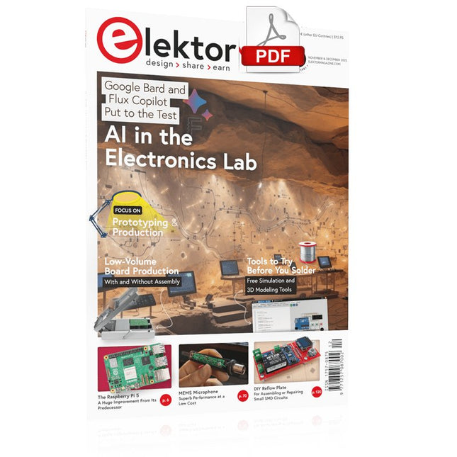
Elektor Digital Elektor November/December 2023 (PDF)
Elektor GREEN and GOLD members can download their digital edition here. Not a member yet? Click here. The Raspberry Pi 5A Huge Improvement From Its Predecessor AI in the Electronics LabGoogle Bard and Flux Copilot Put to the Test Arduino Nano Waveform GeneratorNano + Code = Function Generator Solar-Powered Christmas GarlandAn Eco-Friendly Solution for Garnishing Your Balcony USB Killer DetectorBetter Safe Than Sorry A Simple CNCed EnclosureWith Autodesk Fusion 360 for Personal Use Low-Volume Board ProductionWith and without Assembly IoT Simulation Simplified with WokwiDeveloper Uri Shaked on Design, Software, and More A Bare-Metal Programming Guide (Part 3)CMSIS Headers, Automatic Testing, and a Web Server LoRa, a Swiss Army Knife (2)The Hardware and Software MEMS Microphone Design and Construction Tools to Try Before You SolderSimulation and 3D Modeling Tools That Can Be Used for Free New Tools From Microchip!PICkit 5 and MPLAB ICD 5 Available Now! Rapid Prototyping of Flexible, Stretchable ElectronicsHow the Voltera NOVA Speeds Up Innovation in Wearable Electronic Systems Galvanic IsolationUsing Phototransistor Optocouplers Successfully The Complex Solution or the Anybus Solution?Embedded Industrial Ethernet in 2 Days Rather Than Many Months Your Essential DFM ChecklistHow to Start Designing for Manufacture 3D Printing FilamentsTypes, Features and Use in Prototyping Specialists for Effective Signal Analysis from ELF to EHF BandAaronia’s latest real-time SPECTRAN® V6 series spectrum analyzers Challenges of DFM Analysis for Flex and Rigid-Flex Design Setting Up an SMT Line The Right Combination for a Reliable Assembly Revolutionizing IndustriesThe Rise of Autonomous Mobile Robots (AMRs) Evolved for More ChallengesRohde & Schwarz Adds Eight-Channel R&S MXO 5 to Next-Generation Oscilloscopes Starting Out in Electronics……Amplifying Differences Mini Reflow PlateFor Assembling or Repairing Small SMD Circuits Don’t Start with a Prototype – Start with a Pretotype!Check That a Market Exists for Your Product Before Warming Your Soldering Iron 2023: An AI OdysseyGetting Help Designing a Physical Project Brussels Is InnovatingSupport for Deep Tech
€ 7,50
-
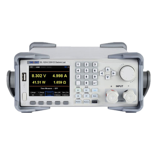
Siglent Siglent SDL1020X-E DC Electronic Load (200 W)
The Siglent SDL1020X-E DC Load leads with measurement resolution of 0.1 mV/0.1 mA and the base SDL1000X-E series resolution is 1 mV/1 mA and adjustable current rise times from 0.001 A/μs~2.5 A/μs. For remote communication and control, the SDL series includes S232/USB/LAN interface types. The SDL1020X-E delivers stability over a wide range of applications and can meet all kinds of testing requirements. including: Power, battery/handheld device design, industry, LED lighting, automotive electronics, and aerospace. Features SDL1020X-E (Single channel): DC 150 V/30 A, total power 200 W 4 static modes / Dynamic mode: CC/CV/CR/CP CC Dynamic mode: Continuous, pulsed, toggled CC Dynamic mode: 25 kHz, CP Dynamic mode: 12.5 kHz, CV Dynamic mode: 0.5 Hz Measuring speed of voltage and current: up to 500 kHz Adjustable current rise time range: 0.001 A/us~2.5 A/us Min. readback resolution: 0.1 mV, 0.1 mA Short-circuit, Battery test, CR-LED mode, and factory test functions 4-wire SENSE compensation mode function List function supports editing as many as 100 steps Program function supports 50 groups of steps OCP, OVP, OPP, OTP and LRV protection External analog control Voltage, Current monitoring via 0-10 V 3.5 inch TFT-LCD display, capable of displaying multiple parameters and states simultaneously Built-in RS232/USB/LAN communication interface, USB-GPIB module (optional) Waveform trend chart and easy-to-use file storage and call functions Includes PC software: Supports SCPI, LabView driver Included 1x Siglent SDL1020X-E DC Programmable Load 1x Quick start guide 1x Guarantee Card 1x Power Cord 1x USB Cable Downloads Datasheet Manual Programming Guide PC Software
€ 531,19
-

Elektor Mai/Juin 2025 (FR)
Le téléchargement intégral de ce numéro est disponible pour nos membres GOLD et GREEN sur le site Elektor Magazine ! Pas encore membre ? Cliquez ici. PbMonitor v1.0Un système de surveillance des batteries pour les applications à onduleurs et de stockage d'énergie contrôleur de charge solaire avec MPPT (1)Principes de base d'un contrôleur de charge solaire pour les systèmes autonomes magnétomètre à intégration du champ et capteurs artisanaux exactitude, ou précision ?vos appareils doivent posséder les deux ! AD7124 : un C/AN de précision en pratiqueFeatures for Sensor Signal Conditioning outil de contrôle PIDOptimisez facilement vos paramètres embedded world 2025 démarrer en électronique...…contrôle de la tonalité Academy Pro BoxLivre + cours en ligne + matériel adaptateur Milliohm-mètreUtilisant la précision de votre multimètre Un nouveau jalon dans le domaine des semi-conducteursEn route vers le 1,4 nm Connecteurs à technologie traversanteLe meilleur des deux mondes : THR fréquencemètrePortable et auto-calibré par GPS compteurs analogiquesDrôles de composants, la série testeur de quartz autonomeQuelle est la précision de votre source d'horloge ? testeur I²C peu couteuxconnecter des appareils I²C directement à votre PC sur le vifbienvenue chez les Pt’tites 2025 : une odyssée de l'IAL'impact transformateur sur le développement de logiciels projet 2.0Corrections, mises à jour, et courrier des lecteurs synthétiseur MIDI autonome Raspberry Pi (2)Améliorons notre configuration avec l’Intelligence oscillateur à pont de Wien "nortonisé"Petite cause, grand effet tester un microcontrôleur à 0,10 $Le microcontrôleur CH32V003 RISC-V et MounRiver Studio en pratique un lecteur audio avec égaliseur basé sur un FPGA (2)Ajout d'un réglage du volume, d'un mixage avancé et d'une interface Web
€ 15,50
-
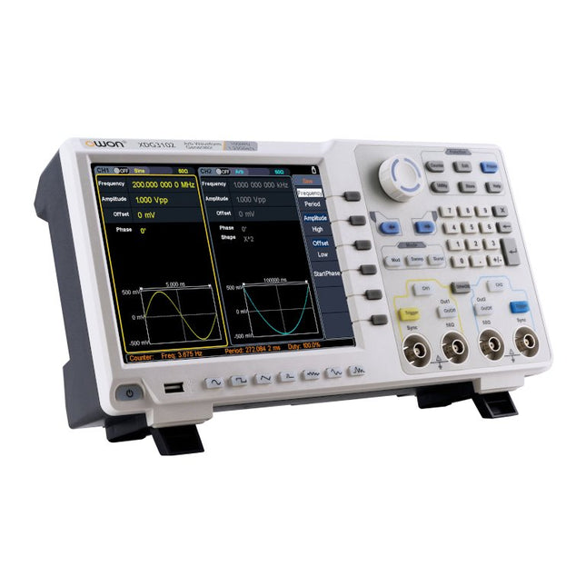
OWON OWON XDG3102 2-ch Arbitrary Waveform Generator (100 MHz)
Features Advanced DDS technology, up to 250 MHz frequency output 1.25 GS/s sampling rate, and 1 μHz frequency resolution Up to 1M arbitrary waveform length Vertical resolution: 14 bits Comprehensive waveform output: 6 groups waveforms, and 152 group built-in arbitrary waveforms Comprehensive modulation options: AM, FM, PM, FSK, 3FSK, 4FSK, PSK, OSK, ASK, BPSK, PWM, sweep, and burst High-accuracy frequency counter integrated, ranging from 100MHz till 200MHz SCPI and LabVIEW supported 8-inch 800 x 600 pixels touch screen LCD Specifications XDG3102 Channel 2 Frequency Output 100MHz Sample Rate 1.25GSa/s Vertical Resolution 14 bits Waveform Standard Waveform sine, square, pulse, ramp, noise, and harmonic Arbitrary Waveform exponential rise, exponential fall, sin(x)/x, step wave, and others, total of 150 built-in waveforms, and user-defined arbitrary waveform Frequency (resolution 1μHz) Sine 1μHz - 100MHz Square 1μHz - 40MHz Pulse 1μHz - 25MHz Ramp 1μHz - 5MHz Harmonic 1μHz - 50MHz Noise 120MHz (-3dB, typical) Arbitrary Waveform built-in waveform: 1uHz - 15MHzuser-defined waveform: 1uHz - 50MHz Accuracy ±1ppm, 0°C - 40°C Amplitude Amplitude (50Ω) 1mVpp - 10Vpp (≤40MHz); 1mVpp - 5Vpp (≤80MHz) 1mVpp - 2.5Vpp (≤120MHz); 1mVpp - 1Vpp (≤250MHz) Amplitude(high impedance) 2mVpp - 20Vpp (≤40MHz); 2mVpp - 10Vpp (≤80MHz); 2mVpp - 5Vpp (≤120MHz); 2mVpp - 2Vpp (≤250MHz) Resolution 1mV or 4 digits DC Offset Range (50Ω) ±(5 Vpk - Amplitude Vpp/2) Range (high-Z, open circuit) ±(10 Vpk - Amplitude Vpp/2) Accuracy ±(1% of |setting| + 1mV + Amplitude Vpp x 0.5%) Resolution 1mV or 4 digits Load Impedance 50Ω (typical) Accuracy ±(1% of setting + 1 mVpp) (typical, 1kHz sine, 0V offset) Sine Wave Spectrum Purity Harmonic Distortion Typical (0dB) DC - 1MHz: <-65dBc 1MHz - 10MHz: <-60dBc 10MHz - 120MHz: <-50dBc 120MHz - 200MHz: <-45dBc Total Harmonic Distortion <0.05 %, 10 Hz to 20 kHz, 1 Vpp Spurious (non-harmonic), Typical (0dB) ≤10MHz: <-70dBc >10MHz: <-70dBc + 6dB/ octave Phase Noise Typical (0 dBm, 10 kHz deviation) 10MHz: ≤-110dBc/Hz Square Rise/Fall Time <5ns Overshoot <3% Duty Cycle 50.0% (fixed) Jitter (rms) 300ps + 100ppm Pulse Pulse Width 12ns - 996875s Leading/Trailing Edge Time ≧7ns Overshoot <3% Jitter (rms) 300ps + 100ppm Ramp Linearity ≤1% of peak output (typical, 1kHz, 1 Vpp, 50% symmetry) Symmetry 0% to 100% Harmonic Harmonic Order ≤16 Harmonic Type even, odd, all, user Harmonic Amplitude could be set for all the harmonics Harmonic Phase Arbitrary Waveform Length 2 points - 1M points Vertical Resolution 14 bits Minimum Rise/Fall Time <7ns Jitter (rms) 3ns Modulation Type AM, FM, PM, PWM, FSK, 3FSK, 4FSK, PSK, OSK, ASK, BPSK, sweep, and burst AM Carrier Waveform sine, square, ramp, and arbitrary (except DC) Source internal / external Modulating Waveform sine, square, ramp, noise, and arbitrary Depth 0.0% - 100.0% Modulating Frequency 2 mHz - 100 kHz FM Carrier Waveform sine, square, ramp, and arbitrary (except DC) Source internal / external Modulating Waveform sine, square, ramp, noise, and arbitrary Modulating Frequency 2 mHz - 100 kHz PM Carrier Waveform sine, square, ramp, and arbitrary (except DC) Source internal / external Modulating Waveform sine, square, ramp, noise, and arbitrary Phase Deviation 0° - 180° Modulating Frequency 2 mHz - 100 kHz PWM Carrier Waveform pulse Source internal / external Modulating Waveform sine, square, ramp, noise, and arbitrary Width Deviation 0 ~ minimum (pulse duty ratio, 100% - pulse duty ratio) Modulating Frequency 2 mHz - 100 kHz FSK / 3FSK / 4FSK Carrier Waveform sine, square, ramp, and arbitrary (except DC) Source internal / external Modulating Waveform square with 50% duty cycle Key Frequency 2 mHz - 1MHz PSK Carrier Waveform sine, square, ramp, and arbitrary (except DC) Source internal / external Modulating Waveform square with 50% duty cycle Key Frequency 2 mHz - 1MHz OSK Carrier Waveform sine, square, ramp, and arbitrary (except DC) Source internal Oscillation Time square with 50% duty cycle Key Frequency 2 mHz - 1MHz ASK Carrier Waveform sine, square, ramp, and arbitrary (except DC) Source internal / external Modulating Waveform square with 50% duty cycle Key Frequency 2 mHz - 1MHz BPSK Carrier Waveform sine, square, ramp, and arbitrary (except DC) Source internal Modulating Waveform square with 50% duty cycle Key Frequency 2 mHz - 1MHz Sweep Carrier Waveform sine, square, ramp, and arbitrary (except DC) Type linear, and log Direction up, and down Sweep Time 1 ms to 500s, ± 0.1% Trigger Source internal, external, and manual Burst Carrier Waveform sine, square, ramp, pulse, and arbitrary (except DC) Burst Count 1 to 50,000 period, infinite, gating Internal Period 10 ns - 500 s Gated Source external trigger Frequency Counter Function frequency period, +width, -width, +duty, and -duty Frequency Range 100 MHz - 200 MHz Frequency Resolution 7 digits Input / Output Display 8”800 x 600 pixels touch screen LCD Type frequency counter, external modulation input,external trigger input,external reference clock input / output Communication Interface USB Host, USB Device, and LAN Dimension 340 x 177 x 90 mm Weight 2.50 kg
€ 650,00
-

Elektor Digital Elektor Juillet/Août 2025 (PDF) FR
Le téléchargement intégral de ce numéro est disponible pour nos membres GOLD et GREEN sur le site Elektor Magazine ! Pas encore membre ? Cliquez ici. tableau de bord OBD2Des cadrans anciens aux données en temps réel OBD2 : ajoutez un compte-tours et un indicateur de changement de vitesse à votre voitureRétro, mais extrêmement utile capteurs de vision et LiDAR pour la robotique Sensor+Test 2025 et PCIM 2025 mesures sans contact du champ électrique (1)Membrane vibrante pour mesurer des tensions continues ou des champs électriques statiques détecteur de courrier sans filCapteurs optiques, radars… quelques options à explorer Elektor Mini-WheelieUn robot auto-équilibré cellules solairesDrôles de composants, la série premiers pas avec un capteur radar moderneUn capteur précis qui ne passe pas inaperçu sur le vifUsine de papier CybersécuritéDes temps difficiles pour les hackers Infographie : IdO et capteurs le Bluetooth 6.0 pour des applications de télémétrie amélioréesCette nouvelle version offre des fonctions de localisation améliorées découvrez la communication sans fil avec BeagleY-AI Projet 2.0Corrections, mises à jour et courrier des lecteurs démarrer en électronique……Conclusion sur les ampli-op un puissant assistant de codage de l'IAAccélérez votre développement avec Continue et Visual Studio Code contrôleur de charge solaire avec MPPT (2)Le circuit détecteur d'obstacles à ultrasonsUn projet simple pour aider les malvoyants une odyssée de l'IABilan du premier semestre synthétiseur MIDI autonome Raspberry Pi (3)plus intelligent avec une interface utilisateur Meshtastic : un projet de démoUn réseau intelligent de noeuds LoRa générateur analogique de fréquences audioGénérateur de signaux sinusoïdaux de haute qualité à fréquence réglable
€ 10,95
-

Elektor Digital Elektor Maart/April 2025 (PDF) NL
Elektor GREEN en GOLD leden kunnen deze uitgave hier downloaden. Nog geen lid? Klik hier om een lidmaatschap af te sluiten. De open-source processorarchitectuur RISC-V16 boards en MCU's die je moet kennen Een FPGA-gebaseerde audiospeler met equalizer (1)Digitaal audio mixen met een Arduino MKR Vidor 4000 Laserkop voor pico-gebaseerde zandklokTekenen met licht Doe mee aan de STM32 Edge AI Contest Een multi-sensor plantenmonitor-systeemdraadloze meting van watertoevoer en lichtomstandigheden Maixduino AI-gestuurde automatische portiergezichtsdetectie met een camera Embedded Electronics 2024AI gaat de industrie opnieuw vormgeven Lading-gebaseerde in-Memory computing bij EnCharge AI AI-Inferentie met 10 Keer Lager Energieverbruik en 20 Keer Lagere Kosten Click board ondersteunt het ontwikkelen en trainen van ML-modellen voor trillingsanalyse De Elektor Mini-WheelieEen kit voor een zelfbalancerende robot MCU, ik zie jeMCUViewer: open-source multiplatform debugging-tool USB 2.0-isolatorelektrisch geïsoleerde USB-aansluiting Voorkomen is betervoorspellend onderhoud in de praktijk SPoE – Elektromagnetische compatibiliteitSingle pair met Power-over-Ethernet door de ogen van EMC Retro techEen nieuwe wereld met kleurentelevisie ECG-monitorimplementatie met Hexabitz-modules en een STM32CubeMonitor De strijd om AI aan de edge Met HaLow Wi-Fi is een record afstand bereikt van 16 km op 900 MHz Eerste CHERI RISC-V Embedded Chip en Early Access programma Derde generatie bosbranddetectie maakt gebruik van satellietverbindingen Uit het leven gegrepenkeuzestress Alle begin......filtert verder en regelt tonen Quasi-analoog uurwerkwedergeboorte van een Elektor-klassieker Een modulaire sensortesterSensor-evaluatieboard met ESP32-S3 2025: Een AI-OdysseeDe opkomst van foundation modellen en hun rol in het democratiseren van AI Raspberry Pi standalone MIDI-synthesizer (1)voorbereiding van een platform voor enkele edge-AI-experimenten Err-lectronicsCorrecties, updates en brieven van lezers Universele AI RISC-V processor doet ze allemaal - CPU, GPU, DSP, FPGA Interview met de CEO: Ventiva's dunne en coole technologie Dual-core programmeren met een Raspberry Pi Picoduik in de wereld van parallel programmeren
€ 9,95
-

Elektor Januari/Februari 2026 (NL)
Elektor GREEN en GOLD leden kunnen deze uitgave hier downloaden. Nog geen lid? Klik hier om een lidmaatschap af te sluiten. Low-noise laboratorium voeding (1)Een stabiele voedingsbron voor gevoelige circuits STM32 Edge-AI Contest 2025: De winnaars Batterijen van vandaagTechnologie en verschillen in lithiumbatterijen Instelbare elektronische belastingStatische en dynamische DC-belasting Step-down converter van 48 V naar 5 VHet verhaal achter de ontwikkeling van een schakeling Autonome sensornode v2.0Deel 2: Hardware-validatie en vermogensoptimalisatie VaristorenVreemde onderdelen Grafische netfrequentiemeterControleer de kwaliteit van het stroomnet Alle begin......maakt er een eind aan Piekstroombelasting SMD-ferrietenBeter bestand tegen stroompieken Elektor Live! Expert Day 2025 Energy harvesting belooft de implementatie van IoT- en IIoT-toepassingen te zullen versnellenHoe energy harvesting IoT loskoppelt van het stroomnet Fnirsi DPS-150Compacte draagbare voeding en converter Instelbare USB-C voedingsbronMaak van uw USB-C-lader een regelbare voeding Eenvoudige lader en capaciteitstesterMet twee goedkope kant-en-klaar modules Slimme kleurendetector met AI-stem en afspeelfunctie PbMonitor v2.0Overzicht van het vernieuwde accu-bewakingssysteem Een ventilator voor de mini-reflow plateSlimme aanpassingen die de resultaten verbeteren Uit het leven gegrepende tsunami der verwendheid Err-lectronicsCorrecties, updates en lezersbrieven 2026: Een AI-odysseeWanneer modellen de hardware bepalen Precisie pico-ampèremeter (2)Montage, kalibratie en test Draadloze energievoorziening van apparatenMet inductieve technologie Autonoom rijden op basis van AIDe Self Driving Challenge 2024 van de RDW Geluidskaart als signaalgeneratorPC als DCF77-testzender
€ 15,95


