
Search results for "usb OR digital OR microscope OR v160"
-

FNIRSI FNIRSI LC1020E High Precision LCR Meter
The FNIRSI LC1020E High-Precision LCR Meter with ESR tester is a portable and intelligent solution for testing electronic components, offering a basic accuracy of up to 0.3%. It is ideal for engineers, technicians, and makers. The device supports L/Q, C/D, and R/D measurements using both series and parallel equivalent circuit models, and features a 2.8-inch TFT color display. With preset thresholds and audio-visual alerts, it enables fast pass/fail evaluation, making it perfect for batch testing and quality control. Supporting test frequencies up to 100 kHz, it is well suited for high-frequency analysis of inductors, capacitors, and resistors. Features ±0.05% accuracy with 4.5-digit resolution Automatic R/L/C identification for fast measurements 5 test frequencies (100 Hz–100 kHz) & 3 voltage levels (0.1–0.6 V) Dual display: L/C/R/Z + X/D/Q/θ/ESR Sorting mode & bias voltage for batch testing Dual ports (3-/5-terminal) with 4-wire Kelvin support Data hold & logging for efficient workflow Compact, rechargeable (3000 mAh) – ideal for lab & field use Specifications General Test Frequency 100 Hz, 120 Hz, 1 kHz, 10 kHz, 100 kHz Basic Accuracy 0.3% Display 2.8-inch TFT LCD display Display Digits Main Parameter: 4.5 digits Secondary Parameter: 4.5 digits Measurement Parameters Main Parameters: AUTO/R/C/L/Z Secondary Parameters: X/D/Q/θ/ESR Measurement Range L: 0-100H C: 0-100mF R: 0-10M Internal Bias 0.0 V, 0.5 V Test Level 0.1 V, 0.3 V, 0.6 V Calibration Functions Open circuit calibration, Short circuit calibration Comparison Function Used to calculate the relative error between the component measurement value and the nominal value, displayed as a percentage, and provides filtering results. Nominal values and tolerance can be set, with tolerance range adjustable from 0.1% to 99.9% Function Record Checks if the measured component data meets the set nominal value and tolerance, recording the number of successful and failed measurements Test Terminal Configuration Three-terminal, Five-terminal Output Impedance 100Ω Interface USB-C (Virtual serial port) Others Language settings, Screen brightness, Sound settings, Auto power-off, Calibration settings, System information Battery 3000 mAh Lithium battery Dimensions 18.5 x 8.5 x 3.5 cm Weight 680 g Capacitance (C) Range: 1mF-100mF 100 Hz: 5% ±5 digits 1 kHz: 3% ±5 digits 10 kHz: / 100 kHz: / Range: 1uF-1mF 100 Hz: 1% ±4 digits 1 kHz: 0.5% ±5 digits 10 kHz: 2% ±5 digits 100 kHz: 3% ±4 digits Range: 1nF-1uF 100 Hz: / 1 kHz: 0.3% ±2 digits 10 kHz: 0.4% ±2 digits 100 kHz: 1% ±4 digits Range: 1pF-1nF 100 Hz: / 1 kHz: 2% ±2 digits 10 kHz: 1.5% ±2 digits 100 kHz: 2% ±4 digits Inductance (L) Range: 1H-100H 100 Hz: 2% ±5 digits 1 kHz: 2% ±5 digits 10 kHz: / 100 kHz: / Range: 1mH-1H 100 Hz: 0.4% ±5 digits 1 kHz: 0.3% ±2 digits 10 kHz: 0.4% ±3 digits 100 kHz: 2.5% ±5 digits Range: 10uH-1mH 100 Hz: 3% ±5 digits 1 kHz: 0.5% ±4 digits 10 kHz: 0.5% ±3 digits 100 kHz: 1.5% ±5 digits Range: 1uH-10uH 100 Hz: / 1 kHz: 2% ±5 digits 10 kHz: 2% ±5 digits 100 kHz: 4% ±5 digits Resistance (R) Range: 1MΩ-10MΩ 100 Hz: 5% ±4 digits 1 kHz: 3% ±3 digits 10 kHz: / 100 kHz: / Range: 1KΩ-1MΩ 100 Hz: 0.4% ±4 digits 1 kHz: 0.2% ±2 digits 10 kHz: 0.3% ±3 digits 100 kHz: 0.6% ±5 digits Range: 1Ω-1KΩ 100 Hz: 1.5% ±4 digits 1 kHz: 0.3% ±2 digits 10 kHz: 0.3% ±3 digits 100 kHz: 0.6% ±5 digits Range: 10mΩ-1Ω 100 Hz: 4% ±4 digits 1 kHz: 2% ±5 digits 10 kHz: 2% ±5 digits 100 kHz: 5% ±5 digits Included 1x FNIRSI LC1020E LCR Meter 1x Kelvin Test Clip 2x Test Leads (1x black, 1x red) 1x Shorting Plate 1x USB-C Cable 1x Manual Downloads Manual Firmware V1.1
€ 84,95€ 69,95Best Price
-

Siglent Siglent SDS1104X-U 4-ch Oscilloscope (100 MHz)
The SDS1000X-U series employs SPO (Super Phosphor Oscilloscope) technology that provides excellent signal fidelity and performance. It comes with an innovative digital trigger system with high sensitivity and low jitter, and a waveform capture rate of 400,000 frames/sec (sequence mode). The SDS1000X U also employs a 256 level intensity grading display function and a color temperature display mode not found in other models in this class. Another powerful addition is the new 128 k point FFT math function that gives the SDS1000X-U a very high-frequency resolution when observing signal spectra. SDS1000X-U also supports searching and navigating. The features and performance of SIGLENT’s new SDS1000X-U cannot be matched anywhere else in this price class. Features 100 MHz bandwidth Real-time sampling rate up to 1 GSa/s The newest generation of SPO technology Waveform capture rates up to 100,000 wfm/s (normal mode) and 400,000 wfm/s (sequence mode) Supports 256-level intensity grading and color temperature display modes Record length up to 14 Mpts Digital trigger system Intelligent trigger: Edge, Slope, Pulse Width, Window, Runt, Interval, Time out (Dropout), Pattern Serial bus triggering and decoding (Standard), supports protocols I²C, SPI, UART, CAN, LIN Video trigger, supports HDTV 10 types of one-button shortcuts, supports Auto Setup, Default, Cursors, Measure, Roll, History, Display/Persist, Clear Sweep, Zoom and Print Segmented acquisition (Sequence) mode, divides the maximum record length into multiple segments (up to 80,000), according to trigger conditions set by the user Automatic measurement function for 38 parameters as well as Measurement Statistics, Zoom, Gating, Math, History and Reference functions History waveform record (History) function (maximum recorded waveform length is 80,000 frames) 128 k pts FFT, supports Peaks and Markers Math functions (FFT, addition, subtraction, multiplication, division, integration, differential, square root) Large 7 inch TFT LCD display with 800 x 480 resolution Downloads Datasheet Manual Programming Guide
€ 401,00
-
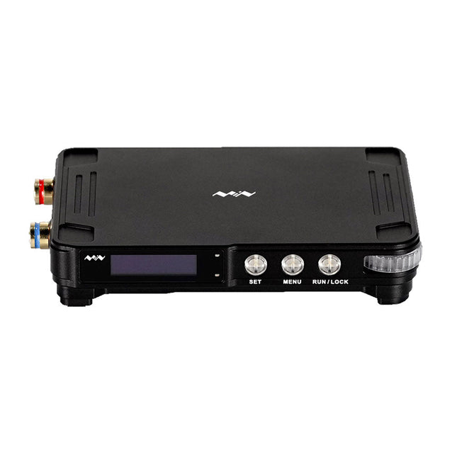
Miniware Miniware MDP-P906 Digital Power Supply (300 W)
MDP-P906 has a built-in cooling fan, and maximum output power of up to 300 W, which meets a wider range of testing needs and application scenarios. Through 2.4 GHz wireless communication, it can be connected to MDP-M01 Smart Digital Monitor module to realize the free combination of multiple channels of 300 W per channel. MDP-P906 has the index, stability and reliability comparable to a professional power supply. It can output pure current, and provide powerful functions such as programmable output, timing output, timing control, automatic compensation, boost mode, etc., making itself a real cost-effective, smart and customized programmable linear DC power supply. MDP-P906 adopts a precision CNC machined aluminum alloy shell, with fine workmanship, novel, mini and beautiful appearance, it completely subverts the rigid image of traditional desktop power supply. With stackable modular design and wireless communication function, MDP-P906 can work independently or paired, both on the workbench, and be carried out for on-site maintenance. MDP-P906 is a perfect solution for electronic engineer, especially field application engineers to meet different needs of power sources. Built-in silent cooling fan, instant cooling, ensure a stable and efficient output! Smart linear compensation, constant voltage & constant current Positive & negative output, series boost, parallel current sharing Applications Universal tests and teaching experiments in R&D laboratory Maintenance of digital products Property verification and fault diagnosis of devices and circuits Emergency power supply for model airplanes and vehicles Power supply testing of RF and microwave circuits or modules Quality control and quality inspection Supply purified power for high-accuracy digital-analog hybrid circuits and Hi-Fi audio devices Specifications Input DC 4.2-30 V/14 A (Max)QC 3.0/PD2.0, 20 V/5 A (Max) Output 0-30 V/0-10 A, 300 W (Max) Conversion efficiency 95% Output resolution 10 mV/2 mA, up to 1 mV/1 mA via Display Control module Output accuracy 0.03%+5 mV0.05%+2 mV Adjustment rate Load adjustment rate <±0.01%Power adjustment rate <±0.01% Ripple and noise <250 uVrms, 3 mVpp; 2 mArms Transient response <4 uS Safety protections Input over-voltage, under-voltage, reverse connection protection, output over-current, back-flow protection and over-temperature protection Others Automatically shut-down and enter micro-power modeSupport USB firmware upgrade Dimensions 112 x 66 x 20 mm Weight 181 g Included 1x MDP-P906 Digital Power Supply 2x Output Cable 1x User Manual Downloads User Manual v1.1 Firmware v1.32
€ 171,95
-

OWON OWON SDS1104 4-ch Oscilloscope (100 MHz)
The OWON SDS1104 oscilloscope is a practical choice for engineers, technicians, students, and hobbyists who need accurate signal analysis without the cost of high-end instruments. With its 100 MHz bandwidth and 1 GSa/s sampling rate, it reliably captures low- to mid-frequency signals, making it well suited for electronics development, troubleshooting, and educational use. Equipped with a 7-inch color TFT display, the SDS1104 provides clear waveform visualization, while automatic measurement functions and FFT analysis help users quickly evaluate frequency, voltage, and timing parameters. Advanced math operations, cursor measurements, and multiple trigger modes add further flexibility, making the oscilloscope a versatile tool for a wide range of testing scenarios. Specifications Bandwidth 100 MHz Sample Rate 1 GS/s Horizontal Scale (s/div) 5ns/div - 1000s/div, step by 1 - 2 - 5 Channel 4 Display 7" color LCD, 800 x 480 pixels Input Coupling DC, AC and GND Vertical Resolution (A/D) Vertical Resolution (A/D) Vertical Sensitivity 5mV/div - 5V/div (at input) Trigger Type Edge, Video Trigger Mode Auto, Normal and Single Waveform Math +, -, x, ÷, invert, FFT Fuse 2A, T class, 250 V Dimension (W x H x D) 301 x 152 x 70 mm Weight 1.1 kg Included 1x OWON SDS1104 Oscilloscope 1x Mains power cord 1x CD Rom 1x Quickstart Guide 1x USB Cable 4x Oscilloscope probe 1x Probe Adjust Downloads Datasheet Manual
€ 249,00
-
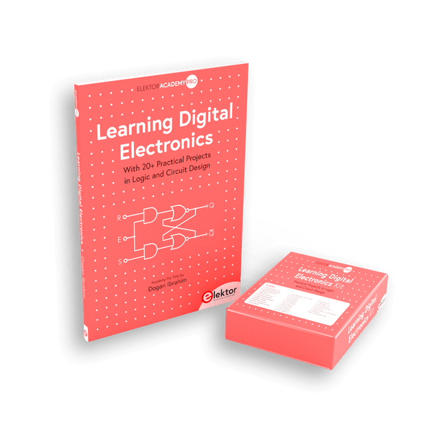
Elektor Bundles Learning Digital Electronics (Bundle)
Master digital electronics – the hands-on way! This bundle includes the book Learning Digital Electronics, featuring 20+ practical projects in Logic and Circuit design, as well as a 100-piece kit – so you can start building logic circuits, counters, displays, and more right away. Learning Digital Electronics (Book) This book is a practical guide to digital electronics, covering the essential components of modern digital systems: number systems, logic gates, Boolean algebra, combinational and sequential logic, and more. Through more than 20 structured projects, you’ll design and build digital systems using real-world components such as logic gates, multiplexers, decoders, flip-flops, counters, and shift registers. The projects range from basic LED logic circuits to digital locks, display systems, traffic light controllers, and timing-based designs. Selected projects introduce the use of tools such as CircuitVerse for circuit simulation, while several designs make use of 74HC-series logic devices, commonly used in digital hardware prototyping. Inside, you’ll find: Clear coverage of number systems and binary arithmetic Logic gate fundamentals and universal gate implementations Step-by-step projects using flip-flops, counters, and registers Real-world design with 74HC-series logic chips Techniques for designing combinational and sequential systems This book takes a design-first, application-driven approach to digital electronics—built around working circuits, tested logic, and hands-on experimentation. Learning Digital Electronics (Kit) This kit has been specially developed to complement the book "Learning Digital Electronics". Since all necessary components are included, you can complete every practical project in the book directly. Kit contents 2x 74HC08 AND gate chip 2x 74HC00 NAND gate chip 1x 74HC86 XOR gate chip 1x 555 timer chip 1x 74HC161 counter chip 1x 74HC164 shift register 1x CD4511 7-segment decoder 1x CD4027 JK flip-flop 1x BC337 NPN transistor 1x KPS-5161 7-segment common-cathode display 1x Light dependent resistor (LDR) 4x 10 KΩ resistors 8x 1 KΩ resistor 2x 47 KΩ resistors 1x 100 KΩ resistor 4x 2.7 KΩ resistors 1x 5.6 KΩ resistor 1x 150 KΩ resistor 1x 10 μF capacitor 2x 0.01 μF capacitor 2x 100 nF capacitor 8x Small red LED 1x Small green LED 1x Small orange LED 4x Pushbutton switches 1x Active buzzer 1x Battery holder for 3x AA batteries (batteries not included) 1x Breadboard 40x Male-to-male jumper wires (length: 200 mm)
€ 69,95€ 59,95Best Price
-

FNIRSI FNIRSI GC-03 Multifunctional Radiation Detector
The FNIRSI GC-03 is a multifunctional radiation detector designed for professional nuclear radiation measurement in everyday environments such as the home, office, car, and outdoors. Equipped with a 2.4-inch high-definition color display, it provides real-time monitoring of nuclear radiation as well as electric and magnetic field strength. For added safety, the device features three alarm modes: audible alert, vibration, and visual light warning. Features 3-in-1 Detection: Monitors electric, magnetic, and nuclear radiation with one device. High-Precision GM Tube: Accurately detects gamma, X-rays, and hard beta radiation with low power consumption. Real-Time Curve + 50 Alarm Records: Tracks radiation trends and stores alarm history for easy review. Custom Triple Alarms: Supports visual, audible, and vibration alerts with adjustable thresholds. Long Battery Life: 1500 mAh battery for extended and reliable field use. Specifications Nuclear Radiation Range: 0.01μSv/h-999.99μSv/h Accuracy: 0.01μSv/h Electric Field Range: 1V/m-1999V/m Accuracy: 1V/m Magnetic Field Range: 0.01μT-99.99μT Accuracy: 0.01μT Radiation Power 0.2-1000mW/m² Detection Radiation Type Ionizing radiation (gamma rays, etc.) Detector Energy compensation GM tube (Geiger counter tube) Dose Current Rate 0.00-10000μSv/h (10mSv/h) Cumulative Dose Equivalent 0.00μSv-500.0mSv Energy Range 48keV-1.5MeV ≤ ±30% (for 137Cs-) Sensitivity 80CPM/μSv Dose Unit μSv/h, uGy/h, mR/h, CPS, CPM Alarm Mode Light, vibration, sound Display 2.4-inch color screen Backlight Brightness Adjustable Power Supply USB-C (5 V/1 A) Battery 1500 mAh Languages English, Chinese Dimensions 138 x 63 x 32 mm Weight 141 g Included 1x FNIRSI GC-03 Radiation Detector 1x USB cable 1x Manual Downloads Manual Firmware v1.0.4
€ 99,95€ 84,95Best Price
-

Rigol Rigol DS1054Z 4-ch Oscilloscope (50 MHz)
Specifications Bandwidth: 50 MHz Analog Channels: 4 Real-time sample rate up to 1 GS/s Memory depth up to 24 Mpts Up to 30,000 wfms/s waveform capture rate Up to 60,000 frames hardware real-time waveform recording and playback functions Innovative 'UltraVision' technology Various trigger and bus decoding functions Low noise floor, vertical scale range: 1 mV/div to 10 V/div Various interfaces: USB Host&Device, LAN (LXI), AUX Compact size, light weight, easy to use 7 inch WVGA (800x480) TFT LCD, intensity graded color display Included 1x Rigol DS1054Z Oscilloscope 1x Power cord 1x USB cable 4x PVP2150 Passive oscilloscope probe (150 MHz)
€ 409,00
-
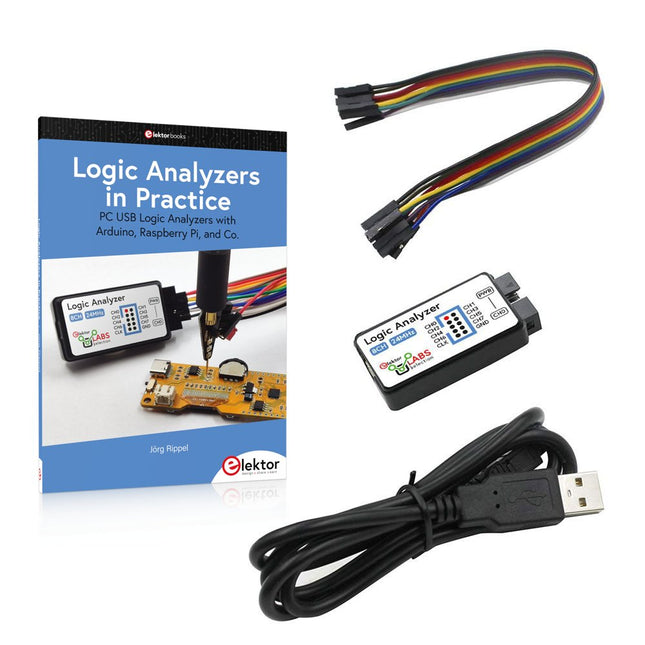
Elektor Bundles Logic Analyzers in Practice (Bundle)
Book: Logic Analyzers in Practice Step-by-step instructions guide you through the analysis of modern protocols such as I²C, SPI, UART, RS-232, NeoPixel, WS28xx, HD44780 and 1-Wire. With the help of numerous experimental circuits based on the Raspberry Pi Pico, Arduino Uno and the Bus Pirate, you will learn the practical application of popular USB logic analyzers. All the experimental circuits presented in this book have been fully tested and are fully functional. The necessary program listings are included – no special programming or electronics knowledge is required for these circuits. The programming languages used are MicroPython and C along with the development environments Thonny and Arduino IDE. This book uses several models of flexible and widely available USB logic analyzers and shows the strengths and weaknesses of each price range. You will learn about the criteria that matter for your work and be able to find the right device for you. Whether Arduino, Raspberry Pi or Raspberry Pi Pico, the example circuits shown allow you to get started quickly with protocol analysis and can also serve as a basis for your own experiments. After reading this book, you will be familiar with all the important terms and contexts, conduct your own experiments, analyze protocols independently, culminating in a comprehensive knowledge set of digital signals and protocols. USB Logic Analyzer (8-ch, 24 MHz) This USB Logic Analyzer is an 8-channel logic analyzer with each input dual purposed for analog data recording. It is perfect for debugging and analyzing signals like I²C, UART, SPI, CAN and 1-Wire. It operates by sampling a digital input connected to a device under test (DUT) at a high sample rate. The connection to the PC is via USB. Specifications Channels 8 digital channels Maximum sampling rate 24 MHz Maximum input voltage 0 V ~ 5 V Operating temperature 0°C ~ 70°C Input impedance 1 MΩ || 10 pF Supported protocols I²C, SPI, UART, CAN, 1-Wire, etc. PC connection USB Dimensions 55 x 28 x 14 mm Downloads Software This bundle contains: Book 'Logic Analyzers in Practice' (normal price: €35) USB Logic Analyzer (8-ch, 24 MHz) (normal price: €20) USB Cable Jumper Wire Ribbon Cable
€ 54,95€ 44,95Best Price
-

Seeed Studio Seeed Studio RF Explorer 3G Combo Spectrum Analyzer
The Seeed Studio RF Explorer 3G Combo is a handheld digital spectrum analyzer and an affordable tool for working across a wide range of popular frequency bands. It is based on a highly integrated frequency synthesizer and a double-balanced mixer, providing high performance, compact dimensions, low power consumption, and excellent value. Designed for both indoor and outdoor use, the RF Explorer 3G Combo can also be connected to a PC via a standard Mini-USB 2.0 connector for additional functionality. This model combines a WSUB1G base unit with an RFEMWSUB3G expansion module, supplied fully assembled and tested. It features two SMA connectors and includes two antennas: a dual-band 144/430 MHz telescopic antenna for sub-GHz frequencies and a helical whip antenna for the 2.4 GHz band. Additional frequency-specific antennas may be required for optimal performance in certain supported frequency ranges. This combination provides the wide frequency coverage of the WSUB3G module together with the high sensitivity and fast response of the WSUB1G unit in the commonly used sub-1 GHz frequency range. Features Pocket size and light weight Solid aluminum metal case Includes a transport EVA carry case for RF Explorer Spectrum Analyzer mode with Peak Max and Hold, Normal, Overwrite and Averaging modes Lifetime free firmware upgrades available, open to community requested features High capacity Lipo for 16+ hours of continuous run, rechargeable by USB Windows PC client Open Source Can be extended with internal Expansion Modules for additional band and functionality Wide band coverage to all popular RF frequencies, starting at 15 MHz and going up to 2.7 GHz. This includes very interesting frequency areas such as 2 m HAM radio, all VHF and UHF, FM radio, GPS, WiFi and WiMax, Bluetooth, etc. Firmware: RF Explorer 3G Combo is delivered with upgraded firmware v1.09. Note some of the features and operation accuracy will be improved in upcoming free firmware revisions. Specifications Battery Lithium Cells / Batteries contained in equipment UN3481 - PI967 Frequency band 15-2700 MHz Frequency span 112 KHz - 600 MHz Graphics LCD 128 x 64 pixels, great visibility outdoors PC Windows client Supports Windows (32 and 64 bits) Backlight For great indoor visibility 2 standard SMA 50 ohms connector, One for Sub-GHz wideband Nagoya NA-773 telescopic antenna included and another 2.4 GHz one for 15-2700 MHz band with helical antenna included. Amplitude resolution 0.5 dBm Dynamic range Left SMA port (WSUB1G) -115 dBm to 0 dBm Right SMA port (WSUB3G) -110 dBm to -10 dBm Absolute Max input power Left SMA port (WSUB1G) +5 dBm Right SMA port (WSUB3G) +30 dBm Average noise level (typical) -110 dBm Frequency stability and accuracy (typical) ±10 ppm Amplitude stability and accuracy (typical) ±6 dBm Frequency resolution 1 KHz Resolution bandwidth (RBW) Automatic 3 KHz to 600 KHz Weight 185 g Dimensions 113 x 70 x 25 mm Included Seeed Studio RF Explorer 3G Combo Spectrum Analyzer Nagoya NA-773 wideband telescopic antenna 2.4 GHz band antenna EVA Case Documentation For more info and to get started with your RF Explorer, visit the start page. For questions and support, please visit https://support.rf-explorer.com
€ 279,95
-
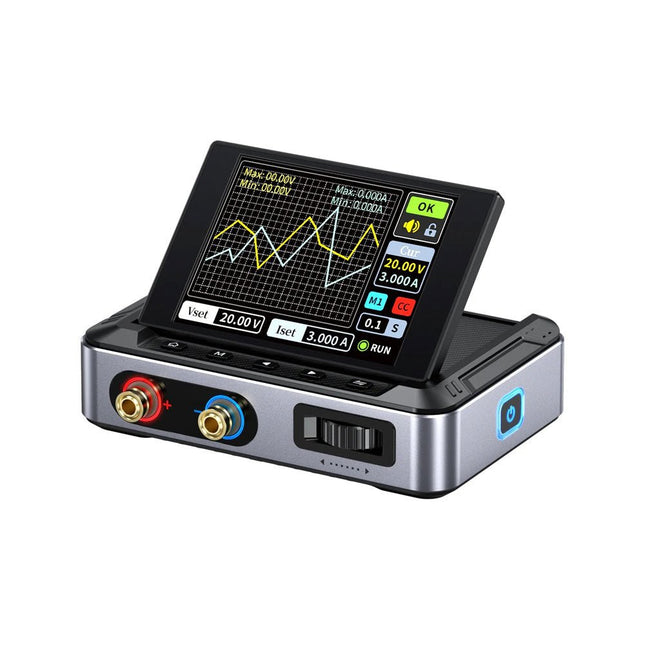
FNIRSI FNIRSI DPS150 DC Power Supply (150 W)
The FNIRSI DPS150 is a high-performance adjustable DC power supply that features a USB-C input interface and multiple power supply modes, allowing precise adjustment of output voltage (0-30 V) and current (0-5 A). It provides efficient, low-consumption, and stable output, equipped with multiple safety protection functions including overvoltage, overcurrent, overload, overheating, and reverse connection. It can be flexibly applied to serial connection of multiple devices, with rich and user-friendly display and operation, compact and portable design, meeting various application needs. Features 30 V, 5 A, 150 W variable DC power with 0.01 V, 0.001 A precision, CC/CV modes, and <20 mV ripple to protect sensitive electronics. Supports PC, QC, and DC inputs with programmable outputs and 6 preset voltage/current settings. Compatible with 4 mm banana plugs, U-shaped terminals, and copper wires for various equipment. 8 safety mechanisms including overvoltage, current, short circuit, and overheating protection. 2.8-inch HD IPS screen with 90° flip, numerical and curve displays for easy monitoring. Small, space-saving design for use in labs, repairs, and DIY projects. Specifications Input Voltage 5~32 V DC Input Current 100 mA-5 A Output Voltage 0-30 V Output Current 0~5 A Output Power 0-150 W Input Way PD fast charger QC fast charger Power bank DC power adapters Operating Environment 0-40°C Load Regulation 0.49% Full Load Efficiency 96.30% Display 2.8 inch (320 x 240) Dimensions 106 x 76 x 28 mm Weight 178 g Included 1x DPS150 Power Supply 2x Alligator clip wires (black & red) 1x Micro USB cable 1x Manual Downloads Manual Firmware V0.0.1
€ 59,00
-
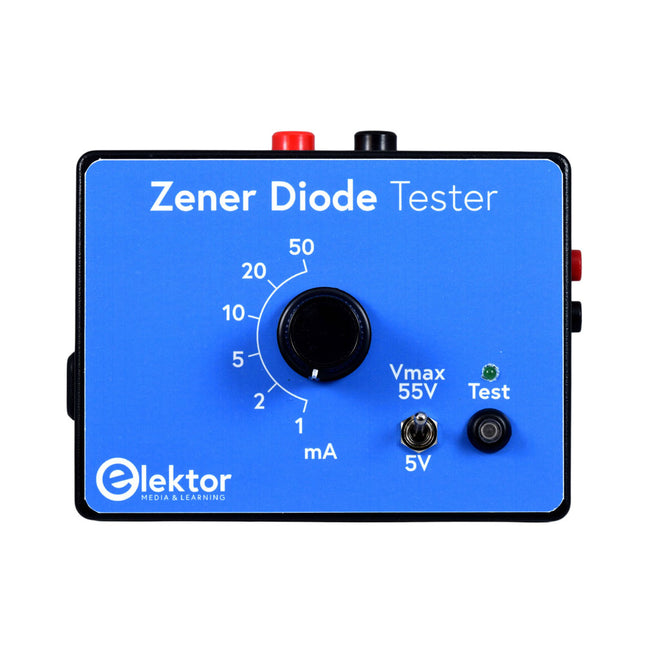
Elektor Zener Diode Tester
The Elektor Zener Diode Tester is essentially a constant-current source that can be switched in steps from 1 to 50 mA. It can be used to test Z-diodes up to a maximum of 54 V. Thanks to a 60-V step-up converter, the device can be powered by the usual 5 to 12 V. The principle of this tester is straightforward. A Z-diode or other DUT (device under test, such as an LED) is biased by an adjustable current source. The voltage across the DUT can be measured with a multimeter. The voltage of most (small) Z-diodes is specified at a current of 5 mA. Depending on the application, the voltage at other currents can also be of interest. That is why six current settings are available: 1, 2, 5, 10, 20, and 50 mA. LEDs are often specified at a current of 20 mA. What can be tested is: Whether a Z-diode is defective (short circuit or high impedance). Whether a Z-diode exhibits the correct Z-voltage. How a Z-voltage changes with different currents. What exact voltage is present at an integrated voltage reference. Whether LEDs in a series chain differ in brightness (hence the 20 mA current). What the current gain is for different base currents in (power) transistors. The kit contains all parts listed in the bill of materials including PCB and enclosure. Specifications Supply voltage 5…12 V/2 A (USB-C) Supply current (Itest = 50 mA) 1.1 A @ 5 V / 412 mA @ 12 V Selectable currents 1, 2, 5, 10, 20, and 50 mA Max. test voltage >54 V @ Itest ≥1 mA Max. output voltage 60 V @ Itest = 0 mA Voltage limit at 5 V 4.5 V @ Itest = 1 mA / 5.18 V @ Itest = 50 mA Enclosure dimensions 110 x 82 x 44 mm PCB size 105.4 x 67.3 mm Connections 4 mm banana sockets for multimeter 2 mm banana sockets for test clips USB-C socket for power supply Included Resistors R1 = 3.3 kΩ, 600 mW, 1% R2 = 0.15 Ω, 1 W, 5%, LS 12.7 mm, ø 3.5 mm R3, R8 = 180 Ω, 600 mW, 1% R4, R6, R16 = 1 kΩ, 600 mW, 1% R5, R19 = 47 kΩ, 600 mW, 1% R7 = 3.9 kΩ, 1 W, 5%, LS 12.7 mm, ø 3.5 mm R9, R10, R12 = 10 kΩ, 600 mW, 1% R11, R13 = 100 Ω, 600 mW 1% R14 = 249 Ω, 600 mW, 1% R15 = 499 Ω, 600 mW, 1% R17 = 2.49 kΩ, 250 mW, 1% R18 = 4.99 kΩ, 250 mW, 1% Capacitors C1 = 470 uF / 35 V, 20%, Ir = 1.86 A, ø 12.5 mm, LS 5 mm, ESR = 0.038 Ω (Panasonic EEUTP1V471) C2 = 1 uF / 100 V, 10%, X7R, LS 5 mm C3 = 2.2 nF / 50 V, 10%, X7R, LS 5 mm C4, C7 = 100 nF / 100 V, 10%, X7R, LS 5 mm C5 = 100 uF / 100 V, 20%, ø 14 mm max., LS 5 mm C6 = 1 nF / 100 V, 10%, X7R, LS 5 mm Inductor L1 = 100 uH, Irms = 2.4 A, Isat = 3.5 A, 0.09 Ω, radial, pitch 2.5/5/10 mm, ø 14 mm max. (Kemet SBC8-101-242) Semiconductors D1 = MUR120G, DO-41 D2, D4 = STPS3150RL, DO-201AD D3 = Z-diode, 18 V, 1.3 W (BZX85C18) D5 = Z-diode, 5.1 V, 0.5 W (1N5231B) LED1 = LED in pushbutton S1 LED2 = LED, green, 3 mm IC1 = MC34063, DIP-8 IC2 = LM4040BIZ-5.0/NOPB, TO-92 (TO-226AA-3) IC3 = TL051CP, DIP-8 T1 = BC327.25, TO-92 T2 = STP40NF10L, TO-220 T3 = IRF9510PBF, TO-220 T4 = 2N7000, TO-92 Others K1, K2, S1, S3 = 2-way screw terminal block, LS 3.5 mm, max. 1.5 mm² connected to K1 = USB-C socket, 30 V/3 A, chassis mounted, wired, 9 x 16 mm connected to K2 = Banana Connector, 2 mm, Socket, 60 VDC, Panel Mount, red (Multicomp 24.102.1) connected to K2 = Banana Connector, 2 mm, Socket, 60 VDC, Panel Mount, black (Multicomp 24.102.2) Test clip, red, 30 VAC/60 VDC (Hirschmann 931467101) Test clip, black, 30 VAC/60 VDC (Hirschmann 931467100) S1 = Pushbutton, panel mount, SPST-NO, 30 DC/100 mA, with red LED S2 = Rotary Switch, 6 position, 2 pole, 30°, 250 V/150 mA S3 = Toggle switch, panel mount, SPDT, solder lugs, 28 VDC T2, T3 = Heat sink, 15°C/W, FK 214 SA-CB Enclosure Hammond 1591XXSSBK, ABS, 110 x 82 x 44 mm Knob for S2, round shaft 6 mm, ø 21 mm, with indicator line (Multicomp CP-LB21-6-6D) 4 x Self-tapping screw #4-1/4", carbon steel, pan head Banana plug, red, 2 mm, 60 VDC (Multicomp 25.205.1) Banana plug, black, 2 mm, 60 VDC (Multicomp 25.205.2) Banana socket, black 4 mm, panel mount Banana socket, red 4 mm, panel mount for LED1, LED2 = Pin header, 1 x 2, vertical, pitch 2.54 mm for LED1, LED2 = Pin socket, 1 x 2, vertical, pitch 2.54 mm for T2, T3 = M3 screw, 10 mm, steel, pan head 2 x M3 washer, plain, steel 4 x M3 nut for IC1, IC3 = DIP-8 socket Wire, black, 0.25 mm² (24 AWG), stranded 14 x 0.15 mm, 1 m Wire, red, 0.25 mm² (24 AWG), stranded 14 x 0.15 mm, 1 m PCB 250772-1 v1.1 Links Article Elektor Labs
€ 99,95€ 79,95Best Price
-
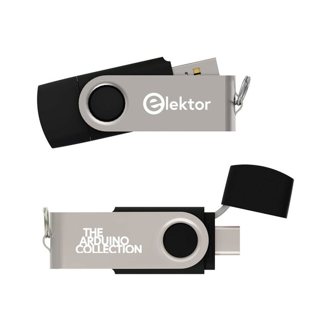
Elektor Classics The Elektor Arduino Collection (USB Stick)
This USB Stick contains more than 300 Arduino-related articles published in Elektor Magazine. The content includes both background articles and projects on the following topics: Software & hardware development: Tutorials on Arduino software development using Arduino IDE, Atmel Studio, Shields, and essential programming concepts. Learning: The Microcontroller Bootcamp offers a structured approach to programming embedded systems. Data acquisition & measurement: Projects such as a 16-bit data logger, lathe tachometer, and an AC grid analyzer for capturing and analyzing real-time signals. Wireless communication: Learn how to implement wireless networks, create an Android interface, and communicate effectively with microcontrollers. Robotics and automation: This covers the Arduino Nano Robot Controller, supporting boards for automation, and explores various Arduino shields to enhance functionality. Self-build projects: Unique projects such as laser projection, Numitron clock and thermometer, ELF receiver, Theremino, and touch LED interfaces highlight creative applications. Whether you're a beginner or an experienced maker, this collection is a valuable resource for learning, experimenting, and pushing the boundaries of Arduino technology.
€ 49,95€ 34,95Best Price


