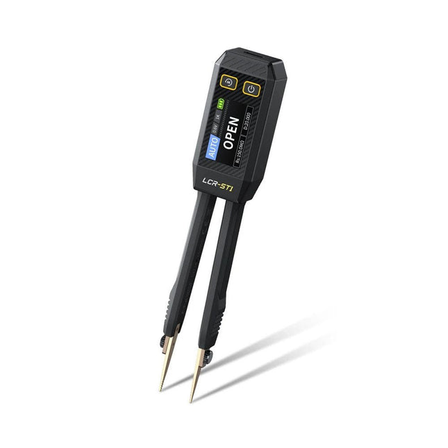
The FNIRSI LCR-ST1 is a compact, multifunctional, and smart LCR tester that supports automatic measurements of resistance, capacitance, inductance, diode testing, and continuity.
Its 1.14-inch color display combined with a convenient magnetic adsorption function enhances ease of use, while the built-in 250 mAh lithium battery ensures long-lasting performance. The device supports three frequency ranges (100 Hz, 1 kHz and 10 kHz) and offers 0.3 V and 0.6 V RMS test levels for versatile testing applications.
The unique tweezer-shaped design of the LCR-ST1 is ideal for delicate tasks in confined spaces and enables fast and accurate testing of electronic components. Its light weight and portable design make it an invaluable tool for both field and laboratory use.
Whether you are an experienced engineer or just starting out in electronics, the LCR-ST1 delivers reliable and accurate measurement results, allowing you to complete your tasks with greater efficiency and precision.
Features
Offers 3 test frequencies (100 Hz, 1 kHz, 10 kHz) and 2 test voltage levels.
Features automatic component identification for faster and more reliable measurements.
High-resolution 1.14-inch color display for clear readouts.
Supports automatic data recording and storage.
The tweezer tips are made from gold-plated brass for enhanced durability and conductivity.
Specifications
Resistance Range
10 mΩ – 10 MΩ
Capacitance Range
1 pF – 22 mF
Inductance Range
1 μh – 10 H
Diode
On voltage 0.7 V
Frequency Test
100 Hz, 1k Hz, 10 KHz
Level Test
0.3 V, 0.6 V RMS
Parameter Display
ESR, D value, Q value, Z value, X value
Display
1.14" HD color screen
Charging Interface
USB-C, 5 V/1 A
Power Supply
Built-in 250 mAh lithium battery
Auto Recognition Measurement
Yes
Replaceable Tweezer Head
Yes
Auto Shutdown
Yes
Data Hold
Yes
History Record
Connect to PC to view and export
Dimensions
28 x 19 x 150 mm
Weight
41 g
Included
1x LCR-ST1 SMD Tweezers
2x Hook Tips
1x Magnetic Patch
1x USB cable
1x Tool bag
1x Manual
Downloads
Manual
Firmware V1.6
The Elektor Super Servo Tester can control servos and measure servo signals. It can test up to four servo channels at the same time.
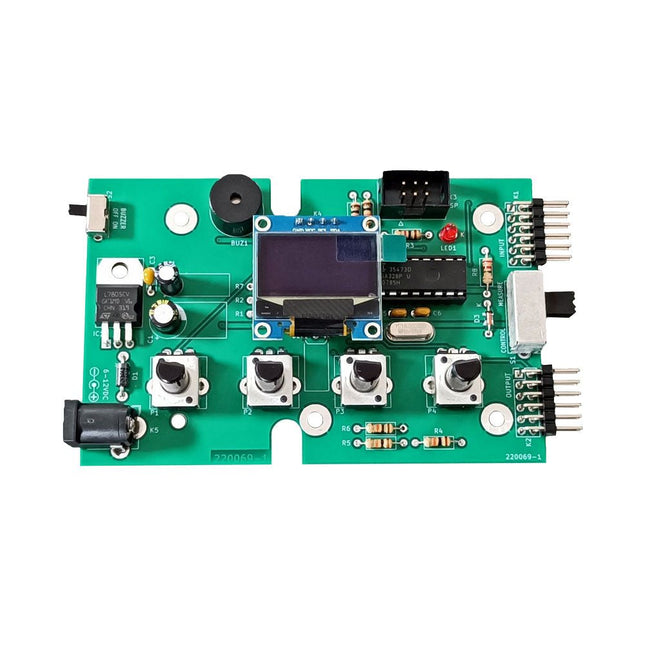
The Super Servo Tester comes as a kit. All the parts required to assemble the Super Servo Tester are included in the kit. Assembling the kit requires basic soldering skills. The microcontroller is already programmed.
The Super Servo Tester features two operating modes: Control/Manual and Measure/Inputs.
In Control/Manual mode the Super Servo Tester generates control signals on its outputs for up to four servos or for the flight controller or ESC. The signals are controlled by the four potentiometers.
In Measure/Inputs the Super Servo Tester measures the servo signals connected to its inputs. These signals may come from for instance an ESC, a flight controller, or the receiver or another device. The signals are also routed to the outputs to control the servos or the flight controller or ESC. The results are shown on the display.
Specifications
Operating modes
Control/Manual & Measure/Inputs
Channels
3
Servo signal inputs
4
Servo signal outputs
4
Alarm
Buzzer & LED
Display
0.96' OLED (128 x 32 pixels)
Input voltage on K5
7-12 VDC
Input voltage on K1
5-7.5 VDC
Input current
30 mA (9 VDC on K5, nothing connected to K1 and K2)
Dimensions
113 x 66 x 25 mm
Weight
60 g
Included
Resistors (0.25 W)
R1, R3
1 kΩ, 5%
R2, R4, R5, R6, R7, R9, R10
10 kΩ, 5%
R8
22 Ω, 5%
P1, P2, P3, P4
10 kΩ, lin/B, vertical potentiometer
Capacitors
C1
100 µF 16 V
C2
10 µF 25 V
C3, C4, C7
100 nF
C5, C6
22 pF
Semiconductors
D1
1N5817
D2
LM385Z-2.5
D3
BZX79-C5V1
IC1
7805
IC2
ATmega328P-PU, programmed
LED1
LED, 3 mm, red
T1
2N7000
Miscellaneous
BUZ1
Piezo buzzer with oscillator
K1, K2
2-row, 12-way pinheader, 90°
K5
Barrel jack
K4
1-row, 4-way pin socket
K3
2-row, 6-way boxed pinheader
S1
Slide switch DPDT
S2
Slide switch SPDT
X1
Crystal, 16 MHz
28-way DIP socket for IC2
Elektor PCB
OLED display, 0.96', 128 x 32 pixels, 4-pin I²C interface
Links
Elektor Magazine
Elektor Labs
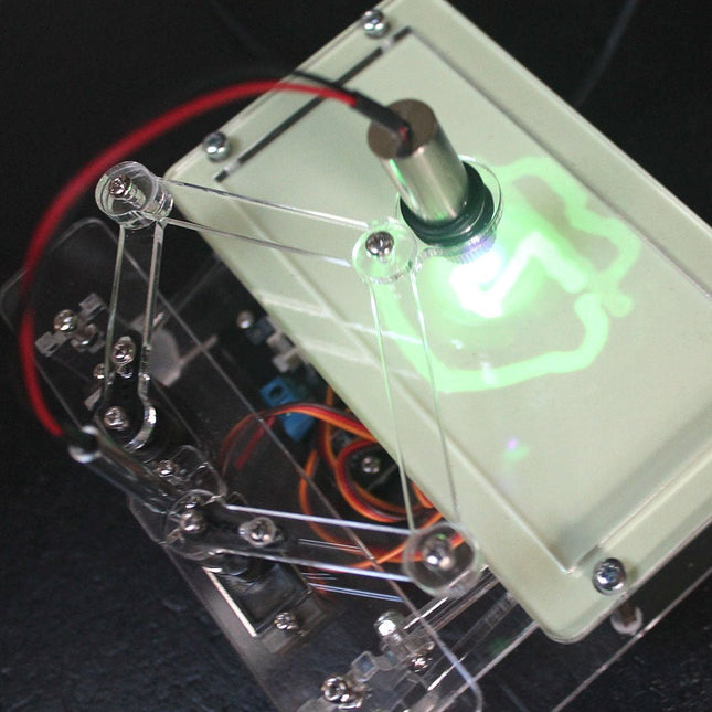
This bundle contains the popular Elektor Sand Clock for Raspberry Pi Pico and the new Elektor Laser Head Upgrade, offering even more options for displaying the time. Not only can you "engrave" the current time in sand, you can now alternatively write it on a glow-in-the-dark foil or create green drawings.
Contents of the bundle
Elektor Sand Clock for Raspberry Pi Pico (normal price: €50)
Elektor Laser Head Upgrade for Sand Clock (normal price: €35)
Elektor Sand Clock for Raspberry Pi (Raspberry Pi-based Eye Catcher)
A standard sand clock just shows how time passes. In contrast, this Raspberry Pi Pico-controlled sand clock shows the exact time by "engraving" the four digits for hour and minute into the layer of sand. After an adjustable time the sand is flattened out by two vibration motors and everything begins all over again.
At the heart of the sand clock are two servo motors driving a writing pen through a pantograph mechanism. A third servo motor lifts the pen up and down. The sand container is equipped with two vibration motors to flatten the sand. The electronic part of the sand clock consists of a Raspberry Pi Pico and an RTC/driver board with a real-time clock, plus driver circuits for the servo motors.
A detailed construction manual is available for downloading.
Features
Dimensions: 135 x 110 x 80 mm
Build time: approx. 1.5 to 2 hours
Included
3x Precut acrylic sheets with all mechanical parts
3x Mini servo motors
2x Vibration motors
1x Raspberry Pi Pico
1x RTC/driver board with assembled parts
Nuts, bolts, spacers, and wires for the assembly
Fine-grained white sand
Elektor Laser Head Upgrade for Sand Clock
The new Elektor Laser Head transforms the Sand Clock into a clock that writes the time on glow-in-the-dark film instead of sand. In addition to displaying the time, it can also be used to create ephemeral drawings. The 5 mW laser pointer, with a wavelength of 405 nm, produces bright green drawings on the glow-in-the-dark film. For best results, use the kit in a dimly lit room. Warning: Never look directly into the laser beam!
The kit includes all the necessary components, but soldering three wires is required.
Note: This kit is also compatible with the original Arduino-based Sand Clock from 2017. For more details, see Elektor Magazine 1-2/2017 and Elektor Magazine 1-2/2018.
The Elektor Laser Head transforms the Elektor Sand Clock into a clock that writes the time on glow-in-the-dark film instead of sand. In addition to displaying the time, it can also be used to create ephemeral drawings. The 5 mW laser pointer, with a wavelength of 405 nm, produces bright green drawings on the glow-in-the-dark film. For best results, use the kit in a dimly lit room. Warning: Never look directly into the laser beam!
The kit includes all the necessary components, but soldering three wires is required.
Note: This kit is also compatible with the original Arduino-based Sand Clock from 2017. For more details, see Elektor Magazine 1-2/2017 and Elektor Magazine 1-2/2018.
The FNIRSI GC-03 is a multifunctional radiation detector designed for professional nuclear radiation measurement in everyday environments such as the home, office, car, and outdoors. Equipped with a 2.4-inch high-definition color display, it provides real-time monitoring of nuclear radiation as well as electric and magnetic field strength. For added safety, the device features three alarm modes: audible alert, vibration, and visual light warning.
Features
3-in-1 Detection: Monitors electric, magnetic, and nuclear radiation with one device.
High-Precision GM Tube: Accurately detects gamma, X-rays, and hard beta radiation with low power consumption.
Real-Time Curve + 50 Alarm Records: Tracks radiation trends and stores alarm history for easy review.
Custom Triple Alarms: Supports visual, audible, and vibration alerts with adjustable thresholds.
Long Battery Life: 1500 mAh battery for extended and reliable field use.
Specifications
Nuclear Radiation
Range: 0.01μSv/h-999.99μSv/h
Accuracy: 0.01μSv/h
Electric Field
Range: 1V/m-1999V/m
Accuracy: 1V/m
Magnetic Field
Range: 0.01μT-99.99μT
Accuracy: 0.01μT
Radiation Power
0.2-1000mW/m²
Detection Radiation Type
Ionizing radiation (gamma rays, etc.)
Detector
Energy compensation GM tube (Geiger counter tube)
Dose Current Rate
0.00-10000μSv/h (10mSv/h)
Cumulative Dose Equivalent
0.00μSv-500.0mSv
Energy Range
48keV-1.5MeV ≤ ±30% (for 137Cs-)
Sensitivity
80CPM/μSv
Dose Unit
μSv/h, uGy/h, mR/h, CPS, CPM
Alarm Mode
Light, vibration, sound
Display
2.4-inch color screen
Backlight
Brightness Adjustable
Power Supply
USB-C (5 V/1 A)
Battery
1500 mAh
Languages
English, Chinese
Dimensions
138 x 63 x 32 mm
Weight
141 g
Included
1x FNIRSI GC-03 Radiation Detector
1x USB cable
1x Manual
Downloads
Manual
Firmware v1.0.4
Practical Low-Cost Methods for Reliable PCB Production
This book explains how to carry out reliable SMD assembly using affordable tools and small-scale equipment. It follows the complete workflow step by step, including tool selection, solder paste handling, stencil use, component placement, reflow methods, inspection, and rework.
The focus is on bench-level and small-lab production rather than industrial assembly lines. It shows practical methods for building single and double-sided SMD boards with repeatable results.
Topics include solder paste and flux, temperature profiles, hot air and hotplate techniques, small reflow ovens, inspection methods, and defect correction. Checklists and example workflows are included to help reduce errors and improve consistency.
Key features:
Tools and supplies for SMD assembly and rework
Solder paste types, storage, and handling
Stencils and paste application methods
Pick and place workflow and component orientation
Temperature profiles and reflow methods
Hot air, hotplate, and reflow oven processes
Inspection and quality control
Common defects such as tombstoning and solder bridges
Practical rework and component replacement
Bench-level professional workflows and checklists
This book is designed as a practical bench reference for anyone who wants to assemble and troubleshoot their own SMD boards with reliable results.
Oscilloscope, multimeter and waveform generator in the same battery-powered device, to work on the go.
Features
Oscilloscope + multimeter + waveform generator, multifunction in one
3.5-inch high-resolution, high-contrast colour LCD display, suitable for outdoor use
18650 lithium battery, comprehensive power consumption ≤3 W, can work continuously for about 6 hours
USB-C interface, support power bank, support PC software connection
Self-calibration function
SCPI supported, facilitate secondary development
Specifications
Oscilloscope
Bandwidth
70 MHz
Channels
2-ch Oscilloscope + 1-ch Generator
Sample Rate
250 MSa/s
Acquisition Model
Normal, Peak detect
Record Length
8K
Display
3.5-inch LCD
Waveform Refresh Rate
10,000 wfrms/s
Input Coupling
DC, AC, and Ground
Input Impedance
1 MΩ ±2%, in parallel with 16pF±10pF
Probe Attenuation Factors
1X,10X,100X,1000X,10000X
Max. input Voltage
400 V (DC+AC, PK-PK, 1MΩ input impedance) (10:1 probe attenuation)
Bandwidth Limit (typical)
20 MHz
Horizontal Scale
5 ns/div - 1000 s/div, step by 1 - 2 - 5
Vertical Sensitivity
10 mV/div - 10 V/div
Vertical Resolution
8 bits
Trigger Type
Edge
Trigger Modes
Auto, Normal, single
Automatic Measurement
Period, Frequency, Mean, PK-PK, Max, Min
Cursor Measurement
ΔV, ΔT, ΔT& ΔV between cursors
Communication Interface
USB Type-C
Multimeter
Max. Resolution
20,000 counts
Testing Mode
Voltage, Current, Resistance, Capacitance, Diode, and Continuity test
Input Impedance
10 MΩ
Max Input Voltage
AC: 750 V | DC: 1000 V
Max Input Current
DC: 10 A | AC: 10 A
Diode
0-2 V
Waveform Generator
Frequency Output
Sine
0.1 Hz - 25 MHz
Square
0.1 Hz - 5 MHz
Ramp
0.1 Hz - 1 MHz
Pulse
0.1 Hz - 5 MHz
Arbitrary
0.1 Hz - 5 MHz
Sampling Rate
125 MSa/s
Channel
1-ch
Amplitude Range
20 mVpp - 5 Vpp
Waveform Length
8K
Vertical Resolution
14 bits
Output Impedance
50Ω
Downloads
User Manual for HDS200 Series
SCPI Protocol for HDS200 Series
Quick Guide for HDS200 Series
PC Software for OWON HDS200 Series
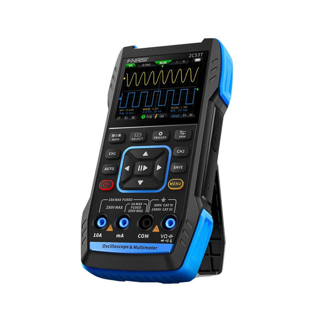
The FNIRSI 2C53T, an enhanced version of its 10 MHz predecessor, is a compact and versatile 3-in-1 device. It combines a dual-channel 50 MHz oscilloscope, a 4.5-digit True RMS multimeter, and a signal generator with 13 waveform types, making it an essential tool for maintenance and research professionals.
Oscilloscope: Features 50 MHz bandwidth, 250 MS/s sampling rate, ±400 V protection, FPGA + ARM + ADC architecture, and waveform saving for analysis.
Multimeter: 4.5-digit True RMS with 19999 counts, supports AC/DC voltage, current, capacitance, resistance, diode, and continuity measurements.
Signal Generator: Outputs 13 signal types up to 50 KHz, with adjustable frequency, amplitude, and duty cycle.
With a 2.8-inch LCD, 3000 mAh battery (6-hour runtime), and a portable design, it delivers powerful functionality in a user-friendly package.
Specifications
Oscilloscope
Channels
2
Analog Bandwidth
50 MHz
Real-time Sampling Rate
250 MS/s
Storage Depth
1 Kpts
Impedance
1 MΩ
Time Base Range
10ns-20s
Vertical Sensitivity
10 mV/div-10 V/div (x1)
Maximum Measured Voltage
±400 V
Trigger Mode
Auto/Normal/Single
Trigger Type
Rising edge, Falling edge
Display Mode
Y-T/Rolling/X-Y
Coupling Method
AC/DC
Persistence
OFF, 500ms, 1s, ∞
Math
8 Basic Operations + FFT
Supported
Waveform Screenshot Save, Export Waveform Image, Cursor Measurement, Infinite Afterglow
Multimeter
DC Voltage
1.9999V/19.999V/199.99V/1000V
±(0.5%+3)
AC Voltage
1.9999V/19.999V/199.99V/750.0V
±(1%+3)
DC Current
19.999mA/199.99mA/1.9999A/9.999A
±(1.2%+3)
AC Current
19.999mA/199.99mA/1.9999A/9.999A
±(1.5%+3)
Resistance
19.999MΩ/1.9999MΩ/199.99KΩ/19.999KΩ
±(0.5%+3)
1.9999KΩ/199.99Ω
±(2.0%+3)
Capacitance
999.9uF/99.99uF/9.999uF/999.9nF/99.99nF/9.999nF
±(2.0%+5)
9.999mF/99.99mF
±(5.0%+20)
Temperature
−55~1300°C (−67~2372°F)
±(2.5%+5)
Continuity Test
Yes
Diode
Yes
Signal Generator
13 Signal Waveforms
Sine wave, rectangular wave, sawtooth wave, half wave, full wave, positive step wave, reverse step wave, exponential rise, exponential fall, DC, multi-audio, Sinker pulse, Lorentz wave
Output Frequency
0-50 KHz
Output Amplitude
0-3 V
Output Duty Cycle
0-100%
General
Display
2.8" HD color screen
Resolution
320 x 240
Charging
USB-C (5 V/1 A)
Battery
3000 mAh Lithium battery
Standby Time
6 hours
Languages
English, Chinese
Dimensions
167 x 89 x 35 mm
Weight
300 g
Differences New vs Old Version
Model
2C53T Upgrade
2C53T Predecessor
Bandwidth
50 MHz
10 MHz
Display Mode
Y-T/Rolling/X-Y
Y-T/Rolling
Math
8 Basic Operations + FFT
N/A
Cursor Function
Yes
N/A
XY Lissau Graph
Yes
N/A
Afterglow Function
Yes
N/A
Multimeter Accuracy
19999 Counts
9999 Counts
Signal Generator
50 KHz
2 MHz
Included
1x FNIRSI 2C53T Oscilloscope (50 MHz)
2x P6100 Oscilloscope probes (10X)
1x Multimeter probe
1x Alligator clip probe
1x USB-C charging cable
1x Storage bag
1x Manual
Downloads
Manual
Firmware V1.2.0
Electronic devices increasingly come with glued displays and batteries. And while the adhesive seal serves as a protection against dirt and water, it complicates the opening procedure of the device and hence its repair.
The iOpener: Warm it through, unstick the glue!
With the help of our iOpener, you can easily and quickly loosen adhesive without risking damage to your device due to overheating with a heat gun. Originally designed for opening Apple iPads, the iOpener is just as suitable for Samsung tablets, Sony smartphones, and devices from any other manufacturer who prefers adhesive over screws.
How it works
Heat the iOpener and place it on your device: Simply heat up the iOpener in the microwave or a pot of boiling water and position it on the edge of your device. The heat will soften the adhesive without damaging your gadget so you can insert an opening pick between the display and the case. Repeat this procedure for all glued areas, the iOpener is reusable any number of times.
Use opening tools to remove adhesive residue: With the right tools, you’re now ready to open your device without hassle. The opening picks are sharp-edged enough to cut through the adhesive strips. Complete the opening procedure by prying up the case with an opening tool or lift your display with a suction cup or an iSclack.
A must-have for electronic repairs
The most annoying part of your repair is done, the rest will be almost a cinch. Whether you are a beginner or a professional, the iOpener should be part and parcel of every toolbox worthy of its name.
Your advantages
Loosen adhesive fastenings
Uncomplicated to heat up in the microwave or boiling water
Reusable
Optionally available with opening tools
Contains food grade glycerine
Saves money and the planet
Included
iOpener
Spudger
iFixit Opening Tool
6x iFixit Opening Picks
iFixit Battery Isolation Pick
Plastic Cards
Suction Cup
Angled Tweezers
Plastic bit driver with magnetic bit socket (4 mm), rubberized handle and swivel cap
Precision bits (4 mm)
Phillips #00
Flathead 2.5 mm
This bundle includes the Arduino UNO Q (2 GB) and the book "Arduino UNO Q and AI".
The Arduino UNO Q is the first UNO board with a hybrid dual-brain architecture, combining a powerful Linux processor with a real-time microcontroller – bringing advanced computing and precise control together on one board.
Powered by a Qualcomm Dragonwing QRB2210 MPU running Debian Linux and a STM32U585 MCU for real-time tasks, the UNO Q is built for next-generation applications. From Edge Computing and AI to robotics and automation, it delivers high performance without sacrificing ease of use.
Simply connect your peripherals and get started – no extra hardware required.
Features
Dual-core architecture: Linux MPU + real-time MCU
Qualcomm Dragonwing QRB2210 with Debian Linux support
STM32U585 microcontroller for deterministic control
Runs Arduino sketches via Zephyr OS
Ideal for AI, IoT, robotics, and industrial projects
Specifications
Microprocessor (MPU)
Qualcomm Dragonwing QRB2210:Quad-core Arm Cortex-A53 @ 2.0 GHzAdreno GPU 3D graphics accelerator2× ISP (13 MP + 13 MP or 25 MP) @ 30 fps
Microcontroller (MCU)
STM32U585Arm Cortex-M33 up to 160 MHz2 MB flash memory786 KB SRAM
RAM
2 GB LPDDR4
Power Supply
From USB-C connector 5 V max at 3 AInput Voltage (VIN): 7-24 V
Storage
16 GB eMMC
USB
1× USB-C port with host/device role switching, power role switch and video output
Connectivity
Wi-Fi 5 (2.4/5 GHz) with onboard antennaBluetooth 5.1 with onboard antenna
Interfaces
I²C/I³CSPIPWMCANUARTPSSIGPIOJTAGADC
Video
Video output support via USB-CMIPI DSI pins on JMEDIA header
Extra
4× RGB user-controllable LEDs8×13 Blue LED Matrix1× Qwiic connector voltage 3V3, I²C1× User push-buttonJCTL: MPU Remote Debug connector
Audio
Microphone IN / Headphone OUT / Line OUT on JMISC
MPU Operating System
Linux Debian OS with upstream support
Real-time Operating System
Arduino Core on Zephyr OS
Containerization
Docker and Docker Compose support
Support Operating Systems for Arduino App Lab
Windows: Windows 10 or later (64-bit)macOS: macOS 11 or later (64-bit)Linux: Ubuntu 22.04 or later, and Debian Trixie (64-bit)
Dimensions
68.85 × 53.34 mm (UNO form factor)
Downloads
Datasheet
User Manual
Pinout
Schematics
Book: Arduino UNO Q and AI – Learn to Build Intelligent Embedded Systems
Build smarter embedded systems with Arduino UNO Q. This book gives you the tools, knowledge, and confidence to turn ideas into intelligent, working solutions using the Arduino UNO Q platform. Discover how to build intelligent embedded systems with the Arduino UNO Q and AI.
Unlock the full potential of the Arduino UNO Q, a next-generation platform that combines the real-time power of the STM32U585 microcontroller with the flexibility of a Qualcomm Dragonwing QRB2210 microprocessor.
Learn how to rapidly prototype real-world applications using the Arduino IDE for low-level embedded control and Python in Arduino App Lab for high-level development.
Build confidence through hands-on projects that guide you step by step from basic board features to complete working systems.
Explore ready-to-use, AI based Arduino App Lab examples and see how they can jump-start your development and reduce time to deployment.
Step into the world of Edge AI with a clear, practical introduction to Edge Impulse Studio—no prior AI experience required.
Follow a complete, real-world workflow to create a Keyword Spotting AI application, covering data collection, model training, optimization, and on-device inference using the Edge Impulse Studio.
Bridge the gap between embedded systems and machine learning and learn how to bring intelligence directly onto your hardware.
Perfect for embedded engineers, educators, students, and makers looking to stay ahead in AI-enabled product development.
This bundle contains:
Arduino UNO Q (2 GB) (normal price: €50)
Book: Arduino UNO Q and AI (normal price: €35)
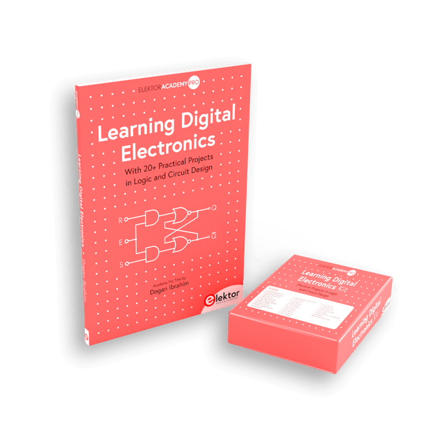
Master digital electronics – the hands-on way!
This bundle includes the book Learning Digital Electronics, featuring 20+ practical projects in Logic and Circuit design, as well as a 100-piece kit – so you can start building logic circuits, counters, displays, and more right away.
Learning Digital Electronics (Book)
This book is a practical guide to digital electronics, covering the essential components of modern digital systems: number systems, logic gates, Boolean algebra, combinational and sequential logic, and more.
Through more than 20 structured projects, you’ll design and build digital systems using real-world components such as logic gates, multiplexers, decoders, flip-flops, counters, and shift registers. The projects range from basic LED logic circuits to digital locks, display systems, traffic light controllers, and timing-based designs.
Selected projects introduce the use of tools such as CircuitVerse for circuit simulation, while several designs make use of 74HC-series logic devices, commonly used in digital hardware prototyping.
Inside, you’ll find:
Clear coverage of number systems and binary arithmetic
Logic gate fundamentals and universal gate implementations
Step-by-step projects using flip-flops, counters, and registers
Real-world design with 74HC-series logic chips
Techniques for designing combinational and sequential systems
This book takes a design-first, application-driven approach to digital electronics—built around working circuits, tested logic, and hands-on experimentation.
Learning Digital Electronics (Kit)
This kit has been specially developed to complement the book "Learning Digital Electronics". Since all necessary components are included, you can complete every practical project in the book directly.
Kit contents
2x 74HC08 AND gate chip
2x 74HC00 NAND gate chip
1x 74HC86 XOR gate chip
1x 555 timer chip
1x 74HC161 counter chip
1x 74HC164 shift register
1x CD4511 7-segment decoder
1x CD4027 JK flip-flop
1x BC337 NPN transistor
1x KPS-5161 7-segment common-cathode display
1x Light dependent resistor (LDR)
4x 10 KΩ resistors
8x 1 KΩ resistor
2x 47 KΩ resistors
1x 100 KΩ resistor
4x 2.7 KΩ resistors
1x 5.6 KΩ resistor
1x 150 KΩ resistor
1x 10 μF capacitor
2x 0.01 μF capacitor
2x 100 nF capacitor
8x Small red LED
1x Small green LED
1x Small orange LED
4x Pushbutton switches
1x Active buzzer
1x Battery holder for 3x AA batteries (batteries not included)
1x Breadboard
40x Male-to-male jumper wires (length: 200 mm)
This bundle includes the Red Pitaya STEMlab 125-14 PRO Gen 2 Starter Kit and the new book "Experimenting with Red Pitaya STEMlab Gen 2".
The Red Pitaya STEMlab 125-14 PRO Gen 2 Starter Kit is a powerful and flexible platform for signal processing, data acquisition, and electronic measurement applications. Designed for engineers, developers, researchers, and educators, this kit provides everything required to start building advanced measurement and control systems.
At the core of the kit is the STEMlab 125-14 PRO Gen 2 board, an upgraded and ultra-lightweight development platform. Powered by the Xilinx Zynq-7010 SoC with 512 MB of RAM, it combines FPGA programmability with ARM processing power to enable high-performance instrumentation and custom signal-processing solutions.
The board offers 14-bit ADC and DAC resolution, a 125 MS/s sampling rate, an input range of ±20 V, and up to 60 MHz bandwidth. Its improved low-noise analog front-end, USB-C connectivity, and compact design make it suitable for demanding applications such as RF development, radar systems, photonics research, software-defined radio (SDR), and industrial automation.
The Starter Kit includes all essential accessories for immediate use: a microSD card with preinstalled operating system, power supply, Ethernet cable for remote access, two 100 MHz oscilloscope probes, and SMA-to-BNC adapters for flexible signal connections.
The Red Pitaya STEMlab 125-14 PRO Gen 2 Starter Kit is an excellent platform for rapid prototyping, FPGA development, measurement instrumentation, and advanced electronics experimentation.
Features
14-bit ADC and DAC resolution
125 MS/s sampling rate
±20 V input range
Up to 60 MHz bandwidth
Xilinx Zynq-7010 SoC (FPGA + ARM processor)
512 MB RAM
Low-noise analog front- and back-ends
Applications
RF development and testing
Radar and wireless systems
Software-defined radio (SDR)
Photonics and optical research
Industrial automation and control systems
Signal analysis and instrumentation
Rapid prototyping of electronic measurement systems
Specifications
Processor
Dual-core ARM Cortex-A9
FPGA
AMD Xilinx Zynq-7010 SoC
RAM
512 MB (4 Gb)
Storage
microSD card (up to 32 GB)
Operating System
Linux-based Red Pitaya OS
ADC Resolution
14-bit
DAC Resolution
14-bit
Bandwidth
60 MHz (DC)
Sampling Rate
125 MS/s
Analog Input Channels
2
Analog Output Channels
2
Input Voltage Range
±1 V (LV) / ±20 V (HV)
Input Impedance
1 MΩ / 10 pF
Output Voltage Range
±1 V
Ethernet
1x Gigabit Ethernet (RJ45)
USB
2x USB-C 2.0 (for power and console)
Digital I/O
16x GPIO (3.3 V)
Communication Interfaces
I²C, SPI, UART, CAN
Power Supply
5 V/3 A via USB-C
Dimensions
106.8 x 60.0 x 17.9 mm
Included
1x Red Pitaya STEMlab 125-14 PRO Gen 2 board
2x 100 MHz oscilloscope probes
2x SMA-to-BNC adapters
1x microSD card with preinstalled OS
1x USB-C Power supply
1x Ethernet cable
Downloads
Documentation
Schematics
Book: Experimenting with Red Pitaya STEMlab Gen 2
With this new book, Red Pitaya goes beyond a versatile board. It becomes a powerful laboratory instrument for precision measurement, analysis, and control.
From the fundamentals of electronic project development, monitoring, control, and design to testing, this book walks you step-by-step through everything you need to know to harness the full potential of Red Pitaya hardware and software.
The book presents real-time, FPGA-based projects that are developed on a PC using the Vivado environment, then transferred to the Red Pitaya for execution and testing.
You will learn about enhanced performance, expanded I/O capabilities, improved FPGA features, and advanced connectivity options that open up new frontiers for precision measurement, monitoring, and control in your embedded applications.
Inside the book you will discover:
A deep dive into Red Pitaya architecture and hardware design
Electronic experiments using Red Pitaya for measurement and monitoring
Hands-on projects using the Python programming language
Practical guidance for FPGA programming using Red Pitaya
Red Pitaya FPGA projects using the Verilog HDL under Vivado IDE
Practical design of electronic projects including measurement and testing
Step-by-step examples that bridge theory and real-world implementation
Whether you are designing your own electronic circuits, developing signal analysis tools, or creating real-time control or monitoring systems, this book provides you the knowledge and confidence you need to fully learn and customize the Red Pitaya platform.