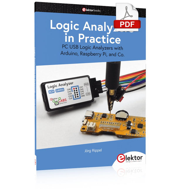
PC USB Logic Analyzers with Arduino, Raspberry Pi, and Co.
Step-by-step instructions guide you through the analysis of modern protocols such as I²C, SPI, UART, RS-232, NeoPixel, WS28xx, HD44780 and 1-Wire. With the help of numerous experimental circuits based on the Raspberry Pi Pico, Arduino Uno and the Bus Pirate, you will learn the practical application of popular USB logic analyzers.
All the experimental circuits presented in this book have been fully tested and are fully functional. The necessary program listings are included – no special programming or electronics knowledge is required for these circuits. The programming languages used are MicroPython and C along with the development environments Thonny and Arduino IDE.
This book uses several models of flexible and widely available USB logic analyzers and shows the strengths and weaknesses of each price range.
You will learn about the criteria that matter for your work and be able to find the right device for you.
Whether Arduino, Raspberry Pi or Raspberry Pi Pico, the example circuits shown allow you to get started quickly with protocol analysis and can also serve as a basis for your own experiments.
After reading this book, you will be familiar with all the important terms and contexts, conduct your own experiments, analyze protocols independently, culminating in a comprehensive knowledge set of digital signals and protocols.
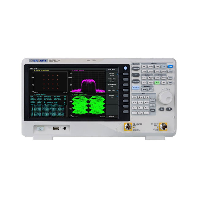
The Siglent SSA3021X Plus spectrum analyzer is a powerful and flexible tool for RF signal and network analysis. With a frequency range of 2.1 GHz, the analyzer delivers reliable automatic measurements and multiple modes of operation: spectrum analyzer the base, optional functions include RF power measurement, vector signal modulation analysis, reflection measurement, and EMI test.
Applications include broadcast monitoring/evaluation, site surveying, S-parameter measurement, analog/digital modulation analysis, EMI pre-compliance test, research and development, education, production, and maintenance.
Features
Spectrum Analyzer Frequency Range from 9 kHz to 2.1 GHz
–161 dBm/Hz Displayed Average Noise Level (Typ.)
–98 dBc/Hz. @ 10 kHz Offset Phase Noise (1 GHz, Typ.)
Level Measurement Uncertainty <0.7 dB (Typ.)
1 Hz Minimum Resolution Bandwidth (RBW)
Preamplifier (Std.)
Tracking Generator (incl. free of charge)
Analog and Digital Signal Modulation Analysis Mode (opt.)
Reflection Measurement Kit (opt.)
EMI Filter and Quasi-Peak Detector Kit (opt.)
Advanced Measurement Kit (opt.)
10.1-inch Multi-Touch Screen , Mouse and Keyboard supported
Web Browser Remote Control on PC and Mobile Terminals and File Operation
Specifications
SSA3015X Plus
SSA3021X Plus
SSA3032X Plus
SSA3075X Plus
Frequency Range
9 kHz ~ 1.5 GHz
9 kHz ~ 2.1 GHz
9 kHz ~ 3.2 GHz
9 kHz ~ 7.5 GHz
Resolution Bandwidth
1 Hz ~ 1 MHz
1 Hz ~ 1 MHz
1 Hz ~ 1 MHz
1 Hz ~ 3 MHz
Phase Noise
<–99 dBc/Hz
<–98 dBc/Hz
<–98 dBc/Hz
<–98 dBc/Hz
Total Amplitude Accuracy
<1.2 dB
<0.7 dB
<0.7 dB
<0.7 dB
Display Average Noise Level
–156 dBm/Hz
–161 dBm/Hz
–161 dBm/Hz
–165 dBm/Hz
Included
Siglent SSA3021X Plus spectrum analyzer
USB cable
Power cord
Quick start guide
Downloads
Datasheet
Manual
Documentation
Firmware
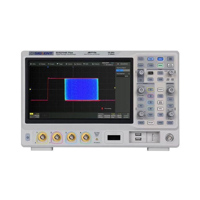
Siglent's SDS2000X Plus series Digital Storage Oscilloscopes are available in bandwidths of 100 MHz, 200 MHz, and 350 MHz, have a maximum sample rate of 2 GSa/s, a maximum record length of 200 Mpts/ch, and up to 4 analog channels + 16 digital channels mixed-signal analysis ability.
The SDS2000X Plus series employs Siglent’s SPO technology with a maximum waveform capture rate of up to 120,000 wfm/s (normal mode, up to 500,000 wfm/s in Sequence mode), 256-level intensity grading display function plus a color temperature display mode. It also employs an innovative digital trigger system with high sensitivity and low jitter. The trigger system supports multiple powerful triggering modes including serial bus triggering. History waveform recording, Sequence acquisition, Search and Navigate functions allow for extended waveform records to be captured, stored, and analyzed. An impressive array of measurement and math capabilities, options for a 50 MHz waveform generator, as well as serial decoding, mask test, bode plot, and power analysis are also features of the SDS2000X Plus. A 10-bit acquisition mode helps to satisfy applications that require more than 8-bit resolution.
The large 10.1’’ capacitive touch screen supports multi-touch gestures, while the remote web control, mouse and external keyboard support greatly improve the operating efficiency of the SDS2000X Plus.
Features
100 MHz, 200 MHz, 350 MHz (upgradable to 500 MHz) models
Real-time sampling rate up to 2 GSa/s
Record length up to 200 Mpts
Serial bus triggering and decoder, supports I²C, SPI, UART, CAN, LIN, CAN FD, FlexRay, I²S and MIL-STD-1553B
Provide 10 bit mode, Vertical and Horizontal Zoom
Capacitive touch screen supports multi-touch gestures
Siglent SDS2000X Plus Oscilloscopes
SDS2102X Plus
SDS2104X Plus
SDS2204X Plus
SDS2354X Plus
Bandwidth
100 MHz
100 MHz
200 MHz
350 MHz
Channels
2
4
4
4
Real-time sampling rate
2 GSa/s
2 GSa/s
2 GSa/s
2 GSa/s
Capture rate
120,000 wfm/s
120,000 wfm/s
120,000 wfm/s
120,000 wfm/s
Memory depth
200 Mpts/ch
200 Mpts/ch
200 Mpts/ch
200 Mpts/ch
Included
Siglent SDS2104X Plus Oscilloscope
Passive probes
Power cord
USB cable
Manual
Downloads
Datasheet
Manual
Quick guide
Manual
Firmware
This bundle is all about designing projects based on the 555 timer IC. The book features over 45 fully tested and documented projects. Together with the kit, which contains more than 130 through-hole components, you can build all the projects described on a breadboard. The setup also makes it easy to modify and experiment with the projects.
Over 45 Builds for the Legendary 555 Chip (and the 556, 558)
Some of the projects in the book are:
Alternately Flashing Two LEDs
Changing LED Flashing Rate
Touch Sensor On/Off Switch
Switch On/Off Delay
Light-Dependent Sound
Dark/Light Switch
Tone Burst Generator
Long Duration Timer
Chasing LEDs
LED Roulette Game
Traffic Lights
Continuity Tester
Electronic Lock
Switch Contact Debouncing
Toy Electronic Organ
Multiple Sensor Alarm System
Metronome
Voltage Multipliers
Electronic Dice
7-Segment Display Counter
Motor Control
7-Segment Display Dice
Electronic Siren
Various Other Projects
Kit Contents
Resistors
1x 15 kΩ
1x 68 kΩ
2x 47 kΩ
1x 82 kΩ
2x 820 Ω
1x 8.2 kΩ
3x 10 kΩ
1x 1.8 kΩ
1x 6.8 kΩ
14x 2.2 kΩ
10x 680 Ω
1x 27 kΩ
1x 5.6 kΩ
1x 560 kΩ
1x 4.7 kΩ
1x 3.3 kΩ
3x 33 kΩ
1x 36 kΩ
2x 100 kΩ
5x 1 kΩ
1x 3.9 kΩ
2x 56 kΩ
2x 12 kΩ
1x 10 kΩ potentiometer
1x 1 MΩ potentiometer
2x 50 kΩ potentiometer
3x 20 kΩ potentiometer
1x 10 kΩ potentiometer
1x 10 kΩ potentiometer
1x 50 kΩ potentiometer
1x 100 kΩ potentiometer
1x 50 kΩ potentiometer
Capacitors
1x 0.33 μF
1x 1 μF
1x 10 nF
1x 22 nF
1x 47 nF
1x 100 nF
1x 10 μF electrolytic
1x 33 μF electrolytic
2x 100 μF electrolytic
LEDs
10x 5 mm red LED
10x 3 mm red LED
3x 3 mm yellow LED
3x 3 mm green LED
1x Common-cathode 7-segment LED
Semiconductors
3x 555 timer
1x CD4017 counter
1x CD4026 counter
1x CD4011 NAND gate
4x 1N4148 diode
1x IRFZ46N MOSFET
1x Thermistor
1x Light dependent resistor (LDR)
Miscellaneous
1x Passive buzzer
1x Active buzzer
1x SG90 servo
1x 8 Ω mini loudspeaker
1x 9 V DC brushed motor
1x 5 V relay
1x 9 V battery clip
7x Pushbutton switches
1x Breadboard
1x Breadboard jumper wires
Pull Down Lever For Highest Score!
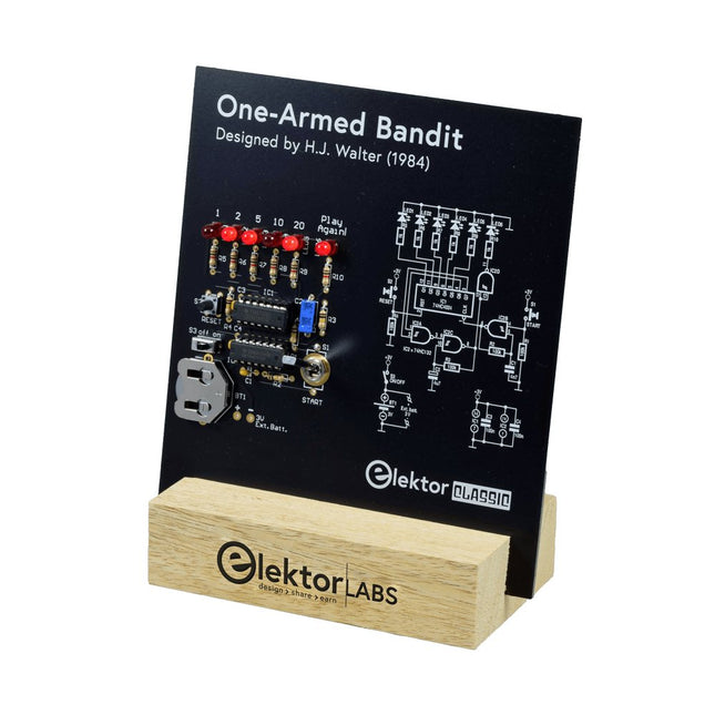
This Elektor Circuit Classic from 1984 shows a playful application of CMOS 400x series logic ICs in combination with LEDs, a highly popular combination at the time. The project imitates a spinning-digit type slot machine.
The Game
To play the game, first agree on the number of rounds. Player 1 actuates the switch lever as long as desired and releases it. The LEDs then show the score which is the sum of the 50-20-10-5 digits lit up. If the Play Again! LED lights, Player 1 has another, “free” round. If not, it’s Player 2’s turn. The players keep tab of their scores, and the highest score wins.
Features
LEDs Indicate Score
Multi-Player and Play Again!
Elektor Heritage Circuit Symbols
Tried & Tested by Elektor Labs
Educational & Geeky Project
Through-Hole Parts Only
Included
Printed Circuit Board
All Components
Wooden Stand
Bill of Materials
Resistors (5%, 250 mW)
R1,R2,R3,R4 = 100kΩ
R5,R6,R7,R8,R9,R10 = 1kΩ
Capacitors
C1 = 4.7nF, 10%, 50V, 5mm
C2 = 4.7μF, 10%, 63V, axial
C3,C4 = 100nF, 10 %, 50V, ceramic X7R, 5mm
Semiconductors
LED1-LED6 = red, 5mm (T1 3/4)
IC1 = 74HC4024
IC2 = 74HC132
Miscellaneous
S1 = switch, toggle, 21mm lever, SPDT, momentary
S2 = switch, tactile, 24V, 50mA, 6x6mm
S3 = switch, slide, SPDT
IC1,IC2 = IC socket, DIP14
BT1 = PCB-mount CR2032 battery retainer clip
Desktop Stand
PCB 230098-1
Not included: BT1 = CR2032 coin cell battery
USB-Logikanalysatoren am PC mit Arduino, Raspberry Pi und Co
Schritt-für-Schritt-Anleitungen führen Sie in die Analyse moderner Protokolle von I²C, SPI, UART, RS-232, NeoPixel, WS28xx, HD44780 und 1-Wire ein. Anhand von zahlreichen Experimentierschaltungen mit dem Raspberry Pi Pico, Arduino Uno und dem Bus Pirate üben Sie die praxisnahe Anwendung gängiger USB-Logikanalysatoren ein.
Alle in diesem Buch vorgestellten Experimentierschaltungen wurden vollständig getestet und sind funktionsfähig. Die notwendigen Programmlistings sind enthalten, es sind keine besonderen Programmier- oder Elektronikkenntnisse für diese Schaltungen notwendig. Es werden die Programmiersprachen MicroPython und C mit den Entwicklungsumgebungen Thonny und Arduino IDE eingesetzt.
Dieses Buch verwendet mehrere Modelle flexibler und weit verbreiteter USB-Logikanalysatoren und zeigt die Stärken und Schwächen jeder Preisklasse. Sie werden kennenlernen, welche Kriterien für Ihre Arbeit wichtig sind und in der Lage sein, das für Sie passende Gerät zu finden.
Egal ob Arduino, Raspberry Pi oder Raspberry Pi Pico: Die abgebildeten Beispielschaltungen ermöglichen einen schnellen Start in die Protokollanalyse und können auch als Grundlage für eigene weitere Experimente dienen.
Sie werden alle wichtigen Begriffe und Zusammenhänge kennenlernen, eigene Experimente durchführen, selbstständig Protokolle analysieren und nach der Lektüre dieses Buches – im Bereich der digitalen Signale und Protokolle – ein umfassendes Wissen aufgebaut haben.
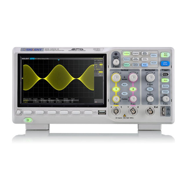
SIGLENT’s SDS1000X-E Series Super Phosphor Oscilloscope is available in one bandwidth, 200 MHz. It has a maximum sample rate of 1 GSa/s and a standard record length of 1 Mpts. For ease-of-use, the most commonly used functions can be accessed with its user-friendly front panel design.
The SDS1000X-E series employs a new generation of SPO (Super Phosphor Oscilloscope) technology that provides excellent signal fidelity and performance. The system noise is also lower than similar products in the industry. It comes with a minimum vertical input range of 500 uV/div, an innovative digital trigger system with high sensitivity and low jitter, and a waveform capture rate of 400,000 frames/ sec (sequence mode).
The SDS1000X-E also employs a 256-level intensity grading display function and a color temperature display mode not found in other models in this class. Siglent’s latest oscilloscopes offering supportsmultiple powerful triggering modes including serial bus triggering. Decoding is standard configuration including IIC,SPI,UART,CAN,LIN. History waveform recording and sequential triggering enable extended waveform recording and analysis.
Another powerful addition is the new 1 million points FFT math function that gives the SDS1000X-E very high frequency resolution when observing signal spectra. The new design also includes a hardware co-processor that delivers measurements quickly and accurately.
The features and performance of Siglent’s new SDS1000X-E cannot be matched anywhere else in this price class.
Specifications
Bandwidth
200 MHz
Channels
2CH+1EXT
Real time sampling rate
1 GSa/s
Memory depth
7 Mpts/CH (Dual-Channel); 14 Mpts/CH (Single-Channel)
Waveform Capture Rate (Max.)
100,000 wfm/s (normal mode); 400,000 wfm/s (sequence mode)
Serial Trigger (Standard)
I²C, SPI, UART/RS232, CAN, LIN
Decode Type (Standard)
I²C, SPI, UART/RS232, CAN, LIN
Trigger Type
Edge, Slope, Pulse Width, Window, Runt, Interval, Dropout, Pattern, Video
Probe (Std)
2 pcs passive probe PP215
Display
7 inch TFT-LCD (800x480)
Weight
Without package 2.5 kg; with package 3.5 kg
Downloads
Datasheet
Manual
Programming Guide
The OWON SDS1102 is an affordable benchtop digital oscilloscope that combines solid performance with essential measurement features. This 2-channel oscilloscope offers a 100 MHz bandwidth, a 1 GS/s sampling rate, a 7-inch LCD display, and a 10 kpts memory depth, making it a practical choice for everyday electronics testing, troubleshooting, and education.
The SDS1102 features a simplified trigger system with level and edge triggering, making it easy to capture and analyze common signals. It is designed for applications that do not require deep memory or advanced trigger functions, offering a straightforward and cost-effective solution for basic signal analysis.
Features
Bandwidth: 100 MHz
2 channels
Sample rate: 1 GS/s
Ultra-thin body
7-inch high-res LCD
SCPI and LabVIEW supported
Specifications
Bandwidth
100 MHz
Horizontal Scale (s/div)
5 ns/div – 1000 s/div
Channel
2
Vertical Sensitivity
5 mV/div – 5 V/div (at input)
DC Gain Accuracy
3%
Vertical Resolution (A/D)
8 bits (2 channels simultaneously)
Input
Input Impedance
1 MΩ, 10 pF
Input Coupling
AC, DC, GND
Max Input Voltage
±400 V, CATI, CATII
Passive probes
х1; х10
Probe Attenuation Factor
х1; х10; х100; х1000
Trigger System
Trigger Mode
Auto, Normal, Single
Trigger Type
Edge, Video
Edge Trigger Source
CH1, CH2
Video Trigger
Sampling Type
Real-time
Sample Rate
1 GS/s
Equivalent Sample Rate
No
Wavelength
10K pts
Interpolation
sin(x)/x
Measurement and Mathematical Treatment System
Automatic Measurement
Vpp, Vavg, RMS, Frequency, Period, Vmax, Vmin, Vtop, Vbase, Width, Overshoot, Pre-shootRise time, Fall time, +Width, -Width, +Duty, -Duty, Delay A→B, Delay A→B, area, cycle area
Math Functions
Addition, Subtraction, Multiplication, Division, FFT
General Characteristics
Display type
7" color LCD
Display Resolution
800 x 480
Power
100-240 V, 45-440 Hz, <15 W
Dimensions
301 x 70 x 152 mm
Weight
1.1 kg
Included
1x OWON SDS1102 Oscilloscope
2x Oscilloscope probes
1x Probe adjust
1x Mains power cord
1x USB cable
1x CD-Rom
1x Quick guide
Downloads
Quick Guide
Manual
PC Software
SCPI Commands
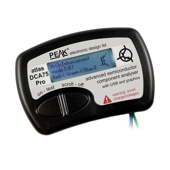
The DCA75 Pro is a great instrument that combines ease-of-use with amazing features. It can automatically identify a huge range of semiconductors, automatically identify pinouts and measure detailed parameters.
Features
Built-in graphics display (now backlit) to show detailed schematic of the component you're testing as well as pinout and measurement data
USB connectivity to allow curve tracing, data storage/retrieval and device matching on your Windows PC (Windows 7 and higher)
Single internal AAA alkaline cell for standalone operation
Component Support
Bipolar transistors (NPN/PNP inc Silicon/Germanium)
Darlington transistors (NPN/PNP)
Enhancement mode MOSFETs (N-Ch and P-Ch)
Depletion mode MOSFETs (N-Ch and P-Ch)
Junction FETs (N-Ch and P-Ch). Both symmetrical and asymmetrical types
Enhancement IGBTs (N-Ch and P-Ch)
Diodes and diode networks (2 and 3 lead types)
Zener diodes (up to about 9 V)
Voltage regulators (up to about 8 V)
LEDs and bi-colour LEDs (2 lead and 3 lead types)
Low power sensitive Triacs and Thyristors (<10 mA trigger and hold)
Measurements
BJT current gain (hFE)
BJT base emitter voltage (Vbe)
BJT collector leakage current
MOSFET on and off gate threshold voltages
MOSFET transconductance
JFET pinch-off voltage
JFET transconductance
JFET IDSS (drain current for Vgs=0)
IGBT on and off gate threshold voltages
IGBT transconductance
Voltage regulator output voltage
Voltage regulator quiescent current consumption
Voltage regulator drop-out voltage
Zener voltage
Diode forward voltage drop
Specifications
Analyzer type
Semiconductor components
Component detection
Automatic
Pinout detection
Automatic, connect any way round
Display type
Graphic LCD (now backlit)
Interface type
USB for optional PC connection
PC functions
Curve tracing (Windows 7 and higher)
Software
Included on USB drive for Windows 7 and higher
Battery
Single AAA cell (supplied)
Included
Peak Atlas DCA75 Pro
PC software on a USB Flash Drive for Windows 11, 10, 8, 7, XP
Micro USB cable
Fitted universal premium hook probes
AAA Alkaline battery
Downloads
Datasheet (EN)
User Guide (EN)
User Guide (IT)
Software Installation Guide (EN)
Software and Firmware Package
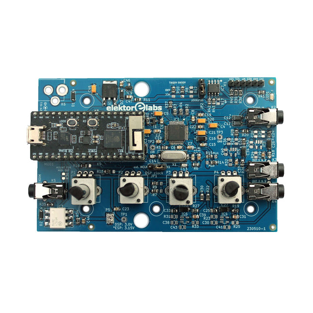
The Elektor Audio DSP FX Processor combines an ESP32 microcontroller and an ADAU1701 Audio DSP from Analog Devices. Besides a user-programmable DSP core, the ADAU1701 has high-quality analog-to-digital and digital-to-analog converters built-in and features an I²S port. This makes it suitable as a high-quality audio interface for the ESP32.
Programs for the ESP32 can be created with Arduino, Platform IO, CMake or by using the Espressif IDF in another way. Programs for the ADAU7101 audio DSPs are created with the free visual programming tool SigmaStudio by dragging and dropping pre-defined algorithm blocks on a canvas.
Applications
Bluetooth/Wi-Fi audio sink (e.g. loudspeaker) & source
Guitar effect pedal (stomp box)
Music synthesizer
Sound/function generator
Programmable cross-over filter for loudspeakers
Advanced audio effects processor (reverb, chorus, pitch shifting, etc.)
Internet-connected audio device
DSP experimentation platform
Wireless MIDI
MIDI to CV converter
and many more...
Specifications
ADAU1701 28-/56-bit, 50-MIPS digital audio processor supporting sampling rates of up to 192 kHz
ESP32 32-bit dual-core microcontroller with Wi-Fi 802.11b/g/n and Bluetooth 4.2 BR/EDR and BLE
2x 24-bit audio inputs (2 V RMS, 20 kΩ)
4x 24-bit audio outputs (0.9 V RMS, 600 Ω)
4x Control potentiometer
MIDI in- and output
I²C expansion port
Multi-mode operation
Power supply: 5 V DC USB or 7.5-12 V DC (barrel jack, center pin is GND)
Current consumption (average): 200 mA
Included
1x ESP32 Audio DSP FX Processor board (assembled)
1x ESP32-PICO-KIT
2x Jumpers
2x 18-pin headers (female)
4x 10 KB potentiometers
Downloads
Documentation
GitHub
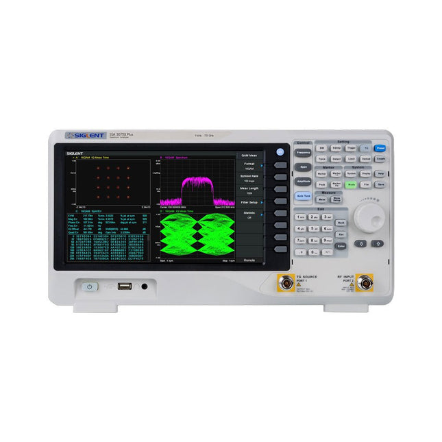
The Siglent SSA3075X Plus spectrum analyzer is a powerful and flexible tool for RF signal and network analysis. With a frequency range of 7.5 GHz, the analyzer delivers reliable automatic measurements and multiple modes of operation: spectrum analyzer the base, optional functions include RF power measurement, vector signal modulation analysis, reflection measurement, and EMI test.
Applications include broadcast monitoring/evaluation, site surveying, S-parameter measurement, analog/digital modulation analysis, EMI pre-compliance test, research and development, education, production, and maintenance.
Features
Spectrum Analyzer Frequency Range from 9 kHz to 7.5 GHz
–165 dBm/Hz Displayed Average Noise Level (Typ.)
–98 dBc/Hz. @ 10 kHz Offset Phase Noise (1 GHz, Typ.)
Level Measurement Uncertainty <0.7 dB (Typ.)
1 Hz Minimum Resolution Bandwidth (RBW)
Preamplifier (Std.)
Tracking Generator (incl. free of charge)
Analog and Digital Signal Modulation Analysis Mode (opt.)
Reflection Measurement Kit (opt.)
EMI Filter and Quasi-Peak Detector Kit (opt.)
Advanced Measurement Kit (opt.)
10.1-inch Multi-Touch Screen , Mouse and Keyboard supported
Web Browser Remote Control on PC and Mobile Terminals and File Operation
Specifications
SSA3015X Plus
SSA3021X Plus
SSA3032X Plus
SSA3075X Plus
Frequency Range
9 kHz ~ 1.5 GHz
9 kHz ~ 2.1 GHz
9 kHz ~ 3.2 GHz
9 kHz ~ 7.5 GHz
Resolution Bandwidth
1 Hz ~ 1 MHz
1 Hz ~ 1 MHz
1 Hz ~ 1 MHz
1 Hz ~ 3 MHz
Phase Noise
<–99 dBc/Hz
<–98 dBc/Hz
<–98 dBc/Hz
<–98 dBc/Hz
Total Amplitude Accuracy
<1.2 dB
<0.7 dB
<0.7 dB
<0.7 dB
Display Average Noise Level
–156 dBm/Hz
–161 dBm/Hz
–161 dBm/Hz
–165 dBm/Hz
Included
Siglent SSA3075X Plus spectrum analyzer
USB cable
Power cord
Quick start guide
Downloads
Datasheet
Manual
Documentation
Firmware
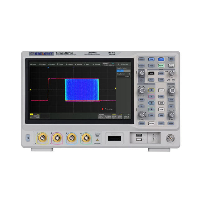
Siglent's SDS2000X Plus series Digital Storage Oscilloscopes are available in bandwidths of 100 MHz, 200 MHz, and 350 MHz, have a maximum sample rate of 2 GSa/s, a maximum record length of 200 Mpts/ch, and up to 4 analog channels + 16 digital channels mixed-signal analysis ability.
The SDS2000X Plus series employs Siglent’s SPO technology with a maximum waveform capture rate of up to 120,000 wfm/s (normal mode, up to 500,000 wfm/s in Sequence mode), 256-level intensity grading display function plus a color temperature display mode. It also employs an innovative digital trigger system with high sensitivity and low jitter. The trigger system supports multiple powerful triggering modes including serial bus triggering. History waveform recording, Sequence acquisition, Search and Navigate functions allow for extended waveform records to be captured, stored, and analyzed. An impressive array of measurement and math capabilities, options for a 50 MHz waveform generator, as well as serial decoding, mask test, bode plot, and power analysis are also features of the SDS2000X Plus. A 10-bit acquisition mode helps to satisfy applications that require more than 8-bit resolution.
The large 10.1" capacitive touch screen supports multi-touch gestures, while the remote web control, mouse and external keyboard support greatly improve the operating efficiency of the SDS2000X Plus.
Features
100 MHz, 200 MHz, 350 MHz (upgradable to 500 MHz) models
Real-time sampling rate up to 2 GSa/s
Record length up to 200 Mpts
Serial bus triggering and decoder, supports I²C, SPI, UART, CAN, LIN, CAN FD, FlexRay, I²S and MIL-STD-1553B
Provide 10 bit mode, Vertical and Horizontal Zoom
Capacitive touch screen supports multi-touch gestures
Siglent SDS2000X Plus Oscilloscopes
SDS2102X Plus
SDS2104X Plus
SDS2204X Plus
SDS2354X Plus
Bandwidth
100 MHz
100 MHz
200 MHz
350 MHz
Channels
2
4
4
4
Real-time sampling rate
2 GSa/s
2 GSa/s
2 GSa/s
2 GSa/s
Capture rate
120,000 wfm/s
120,000 wfm/s
120,000 wfm/s
120,000 wfm/s
Memory depth
200 Mpts/ch
200 Mpts/ch
200 Mpts/ch
200 Mpts/ch
Included
Siglent SDS2354X Plus Oscilloscope
Passive probes
Power cord
USB cable
Manual
Downloads
Datasheet
Manual
Quick guide
Manual
Firmware