
Search results for "official OR case OR for OR raspberry OR pi OR 4 OR black OR gray"
-
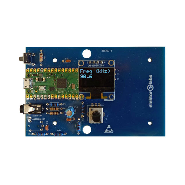
Elektor Labs Elektor AM Transmitter Kit
Build Your Own Vintage Radio Broadcaster The Elektor AM Transmitter Kit allows streaming audio to vintage AM radio receivers. Based on a Raspberry Pi Pico microcontroller module, the AM Transmitter can transmit on 32 frequencies in the AM band, from 500 kHz up to 1.6 MHz in 32 steps of approx. 35 kHz. The frequency is selected with a potentiometer and shown on a 0.96" OLED display. A pushbutton allows toggles the transmitting mode between On and Off. The range of the transmitter depends on the antenna. The onboard antenna provides a range of a few centimeters, requiring the AM Transmitter to be placed close to or inside the radio. An external loop antenna (not included) can be connected to increase the range. The Elektor AM Transmitter Kit comes as a kit of parts that you must solder to the board yourself. Features The board is compatible with a Hammond 1593N enclosure (not included).A 5 VDC power supply with micro-USB connector (e.g., an old phone charger) is needed to power the kit (not included). Current consumption is 100 mA. The Arduino software (requiring Earle Philhower’s RP2040 Boards Package) for the Elektor AM Transmitter Kit plus more information is available at the Elektor Labs page of this project. Component List Resistors R1, R4 = 100 Ω R2, R3, R8 = 10 kΩ R5, R6, R9, R10, R11 = 1 kΩ R7 = optional (not included) P1 = potentiometer 100 kΩ, linear Capacitors C1 = 22 µF 16V C2, C4 = 10 nF C3 = 150 pF Miscellaneous K1 = 4×1 pin socket K2, K3 = 3.5 mm socket Raspberry Pi Pico pushbutton, angle mount 0.96" monochrome I²C OLED display PCB 150292-1
€ 29,95
Best Price
-
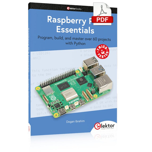
Elektor Digital Raspberry Pi 5 Essentials (E-book)
Program, build, and master over 60 projects with Python The Raspberry Pi 5 is the latest single-board computer from the Raspberry Pi Foundation. It can be used in many applications, such as in audio and video media centers, as a desktop computer, in industrial controllers, robotics, and in many domestic and commercial applications. In addition to the well-established features found in other Raspberry Pi computers, the Raspberry Pi 5 offers Wi-Fi and Bluetooth (classic and BLE), which makes it a perfect match for IoT as well as in remote and Internet-based control and monitoring applications. It is now possible to develop many real-time projects such as audio digital signal processing, real-time digital filtering, real-time digital control and monitoring, and many other real-time operations using this tiny powerhouse. The book starts with an introduction to the Raspberry Pi 5 computer and covers the important topics of accessing the computer locally and remotely. Use of the console language commands as well as accessing and using the desktop GUI are described with working examples. The remaining parts of the book cover many Raspberry Pi 5-based hardware projects using components and devices such as LEDs and buzzers LCDs Ultrasonic sensors Temperature and atmospheric pressure sensors The Sense HAT Camera modules Example projects are given using Wi-Fi and Bluetooth modules to send and receive data from smartphones and PCs, and sending real-time temperature and atmospheric pressure data to the cloud. All projects given in the book have been fully tested for correct operation. Only basic programming and electronics experience are required to follow the projects. Brief descriptions, block diagrams, detailed circuit diagrams, and full Python program listings are given for all projects described.
€ 32,95
Members: € 29,66
-
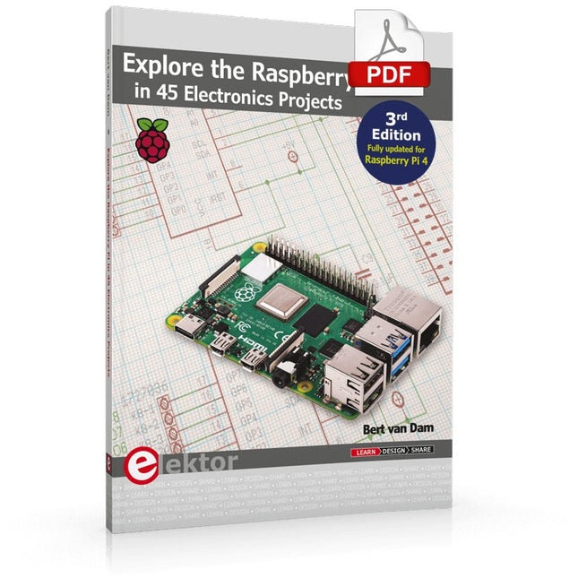
Elektor Digital Explore the Raspberry Pi in 45 Electronics Projects (3rd Edition | E-book)
3rd Edition – Fully updated for Raspberry Pi 4 The Raspberry Pi is a very cheap but complete computer system that allows all sorts of electronics parts and extensions to be connected. This book addresses one of the strongest aspects of the Raspberry Pi: the ability to combine hands-on electronics and programming. Combine hands-on electronics and programming After a short introduction to the Raspberry Pi you proceed with installing the required software. The SD card that can be purchased in conjunction with this book contains everything to get started with the Raspberry Pi. At the side of the (optional) Windows PC, software is used which is free for downloading. The book continues with a concise introduction to the Linux operating system, after which you start programming in Bash, Python 3 and Javascript. Although the emphasis is on Python, the coverage is brief and to the point in all cases – just enabling you to grasp the essence of all projects and start adapting them to your requirements. All set, you can carry on with fun projects. The book is ideal for self-study No fewer than 45 exciting and compelling projects are discussed and elaborated in detail. From a flashing lights to driving an electromotor; from processing and generating analog signals to a lux meter and a temperature control. We also move to more complex projects like a motor speed controller, a web server with CGI, client-server applications and Xwindows programs. Each project has details of the way it got designed that way The process of reading, building, and programming not only provides insight into the Raspberry Pi, Python, and the electronic parts used, but also enables you to modify or extend the projects any way you like. Also, feel free to combine several projects into a larger design.
€ 32,95
Members: € 29,66
-

Elecrow Elecrow AI Starter Kit for Jetson Orin Nano
All-in-One AI Learning and Development Platform for Edge Intelligence This NVIDIA Jetson-based AI Starter Kit is a versatile platform for learning, development, and hands-on experimentation in Edge AI. Designed for use with the NVIDIA Jetson Orin Nano, the kit combines an 11.6-inch IPS display, an 8-megapixel pan-tilt camera, and an AI voice interaction system. It includes 30 functional modules and 38 carefully designed Python courses that progress from beginner to advanced level. The course content covers Python fundamentals, sensor technology, AI vision, and image recognition. With step-by-step practical exercises ranging from basic programming to real-world computer vision applications, this kit provides an ideal platform for students, makers, developers, and anyone looking to explore artificial intelligence and edge computing. Please note: The NVIDIA Jetson Orin Nano is not included. Features Designed for the NVIDIA Jetson Orin Nano AI voice interaction module 8 MP camera with pan-tilt control Supports object and face tracking No soldering or complex wiring required Built-in 11.6-inch IPS display 30 functional modules 38 step-by-step Python lessons I²C, UART, and GPIO expansion interfaces Portable carrying case included Specifications Main Processor Jetson Orin Nano Number of Sensors 30 Sensor Board Design Integrated sensor board, no soldering or complex wiring required Screen 11.6-inch IPS Screen Screen Resolution 1366 x 768 Camera IMX219 8MP Expansion Interfaces 2x I²C, 1x UART, 1x IO D13, 1xIO D12 Programming Environment Based on Python Number of Tutorials 38 creative tutorials Target Audience Students, teachers, hardware enthusiasts Application Scenarios Ideal for learning AI programming, Jetson Orin Nano basics Dimensions 300 x 200 x 100 mm Module List Module Quantity Temperature & Humidity Sensor 1 pcs Button 4 pcs Ultrasonic Ranging Sensor 1 pcs Light Sensor 1 pcs Linear Potentiometer 1 pcs Buzzer 1 pcs LCD 1 pcs Infrared Remote 1 pcs Relay 1 pcs NFC 1 pcs PIR Motion Sensor 1 pcs Joystick 1 pcs 4-Digital Display 1 pcs LED 1 pcs Microphone 1 pcs Speaker 1 pair Vibration Motor 1 pcs Touch Sensor 1 pcs 8x8 RGB Matrix 1 pcs Atmospheric pressure sensor 1 pcs Tilt Switch 1 pcs Stepper Motor 1 pcs Accelerometer & Gyro 1 pcs Gas Sensor (MQ2) 1 pcs Hall Sensor 1 pcs Rotary Encoder 1 pcs U-shaped photoelectric switch 1 pcs NTC 1 pcs Servo 2 pcs Monocular camera 1 pcs Included 1x Elecrow AI Starter Kit for Jetson Orin Nano 1x IR Remote Control 1x NFC Card 1x 128 GB SD Card 1x 40-pin GPIO Cable 2x 22-pin FPC Cable 2x 24-pin FPC Cable 1x Jetson DP & USB Adapter Board Not included NVIDIA Jetson Orin Nano Downloads Manual Wiki OpenClaw Install and Config Guide
€ 249,00
Members: € 224,10
-
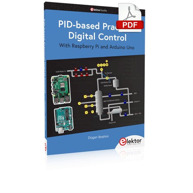
Elektor Digital PID-based Practical Digital Control with Raspberry Pi and Arduino Uno (E-book)
The Arduino Uno is an open-source microcontroller development system encompassing hardware, an Integrated Development Environment (IDE), and a vast number of libraries. It is supported by an enormous community of programmers, electronic engineers, enthusiasts, and academics. The libraries in particular really smooth Arduino programming and reduce programming time. What’s more, the libraries greatly facilitate testing your programs since most come fully tested and working. The Raspberry Pi 4 can be used in many applications such as audio and video media devices. It also works in industrial controllers, robotics, games, and in many domestic and commercial applications. The Raspberry Pi 4 also offers Wi-Fi and Bluetooth capability which makes it great for remote and Internet-based control and monitoring applications. This book is about using both the Raspberry Pi 4 and the Arduino Uno in PID-based automatic control applications. The book starts with basic theory of the control systems and feedback control. Working and tested projects are given for controlling real-life systems using PID controllers. The open-loop step time response, tuning the PID parameters, and the closed-loop time response of the developed systems are discussed together with the block diagrams, circuit diagrams, PID controller algorithms, and the full program listings for both the Raspberry Pi and the Arduino Uno. The projects given in the book aim to teach the theory and applications of PID controllers and can be modified easily as desired for other applications. The projects given for the Raspberry Pi 4 should work with all other models of Raspberry Pi family. The book covers the following topics: Open-loop and closed-loop control systems Analog and digital sensors Transfer functions and continuous-time systems First-order and second-order system time responses Discrete-time digital systems Continuous-time PID controllers Discrete-time PID controllers ON-OFF temperature control with Raspberry Pi and Arduino Uno PID-based temperature control with Raspberry Pi and Arduino Uno PID-based DC motor control with Raspberry Pi and Arduino Uno PID-based water level control with Raspberry Pi and Arduino Uno PID-based LED-LDR brightness control with Raspberry Pi and Arduino Uno
€ 32,95
Members: € 29,66
-
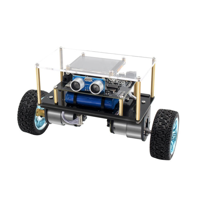
Elektor Labs Elektor Mini-Wheelie Self-Balancing Robot
Arduino-compatible, ESP32-controlled, 2-wheeled Balancing Robot The Elektor Mini-Wheelie is an experimental autonomous self-balancing robot platform. Based on an ESP32-S3 microcontroller, the self-balancing robot is fully programmable using the Arduino environment and open-source libraries. Its wireless capabilities allow it to be controlled remotely over Wi-Fi, Bluetooth or ESP-NOW or to communicate with a user or even another robot. An ultrasonic transducer is available for detecting obstacles. Its color display can be used for displaying cute facial expressions or, for the more down-to-earth users, cryptic debug messages. The robot comes as a neat kit of parts that you must assemble yourself. Everything is included, even a screwdriver. Note: The Mini-Wheelie is an educational development platform intended for learning, experimentation, and robotics development. It is not classified as a toy for children, and its features, documentation, and intended audience reflect this purpose. The product is aimed at students, educators, and developers who wish to explore robotics, programming, and hardware integration in an educational setting. Specifications ESP32-S3 microcontroller with Wi-Fi and Bluetooth MPU6050 6-axis Inertial Measurement Unit (IMU) Two independently controlled 12 V electric motors with tachometer Ultrasonic transducer 2.9" TFT color display (320 x 240) MicroSD card slot Battery power monitor 3S rechargeable Li-Po battery (11.1 V/2200 mAh) Battery charger included Arduino-based open-source software Dimensions (W x L x H): 23 x 8 x 13 cm Included 1x ESP32-S3 Mainboard + MPU6050 module 1x LCD board (2.9 inch) 1x Ultrasonic sensor 1x Battery pack (2200 mAh) 1x Battery charger 1x Motor tyre kit 1x Case board 1x Acrylic board 1x Screwdriver 1x Protective strip 1x Flex cable B (8 cm) 1x Flex cable A (12 cm) 1x Flex cable C 4x Copper column A (25 mm) 4x Copper column B (55 mm) 4x Copper column C (5 mm) 2x Plastic nylon column 8x Screws A (10 mm) 24x Screws B (M3x5) 8x Nuts 24x Metal washers 2x Zip tie 1x MicroSD card (32 GB) Downloads Documentation
€ 89,95
Members: € 80,96
-

FNIRSI FNIRSI LC1020E High Precision LCR Meter
The FNIRSI LC1020E High-Precision LCR Meter with ESR tester is a portable and intelligent solution for testing electronic components, offering a basic accuracy of up to 0.3%. It is ideal for engineers, technicians, and makers. The device supports L/Q, C/D, and R/D measurements using both series and parallel equivalent circuit models, and features a 2.8-inch TFT color display. With preset thresholds and audio-visual alerts, it enables fast pass/fail evaluation, making it perfect for batch testing and quality control. Supporting test frequencies up to 100 kHz, it is well suited for high-frequency analysis of inductors, capacitors, and resistors. Features ±0.05% accuracy with 4.5-digit resolution Automatic R/L/C identification for fast measurements 5 test frequencies (100 Hz–100 kHz) & 3 voltage levels (0.1–0.6 V) Dual display: L/C/R/Z + X/D/Q/θ/ESR Sorting mode & bias voltage for batch testing Dual ports (3-/5-terminal) with 4-wire Kelvin support Data hold & logging for efficient workflow Compact, rechargeable (3000 mAh) – ideal for lab & field use Specifications General Test Frequency 100 Hz, 120 Hz, 1 kHz, 10 kHz, 100 kHz Basic Accuracy 0.3% Display 2.8-inch TFT LCD display Display Digits Main Parameter: 4.5 digits Secondary Parameter: 4.5 digits Measurement Parameters Main Parameters: AUTO/R/C/L/Z Secondary Parameters: X/D/Q/θ/ESR Measurement Range L: 0-100H C: 0-100mF R: 0-10M Internal Bias 0.0 V, 0.5 V Test Level 0.1 V, 0.3 V, 0.6 V Calibration Functions Open circuit calibration, Short circuit calibration Comparison Function Used to calculate the relative error between the component measurement value and the nominal value, displayed as a percentage, and provides filtering results. Nominal values and tolerance can be set, with tolerance range adjustable from 0.1% to 99.9% Function Record Checks if the measured component data meets the set nominal value and tolerance, recording the number of successful and failed measurements Test Terminal Configuration Three-terminal, Five-terminal Output Impedance 100Ω Interface USB-C (Virtual serial port) Others Language settings, Screen brightness, Sound settings, Auto power-off, Calibration settings, System information Battery 3000 mAh Lithium battery Dimensions 18.5 x 8.5 x 3.5 cm Weight 680 g Capacitance (C) Range: 1mF-100mF 100 Hz: 5% ±5 digits 1 kHz: 3% ±5 digits 10 kHz: / 100 kHz: / Range: 1uF-1mF 100 Hz: 1% ±4 digits 1 kHz: 0.5% ±5 digits 10 kHz: 2% ±5 digits 100 kHz: 3% ±4 digits Range: 1nF-1uF 100 Hz: / 1 kHz: 0.3% ±2 digits 10 kHz: 0.4% ±2 digits 100 kHz: 1% ±4 digits Range: 1pF-1nF 100 Hz: / 1 kHz: 2% ±2 digits 10 kHz: 1.5% ±2 digits 100 kHz: 2% ±4 digits Inductance (L) Range: 1H-100H 100 Hz: 2% ±5 digits 1 kHz: 2% ±5 digits 10 kHz: / 100 kHz: / Range: 1mH-1H 100 Hz: 0.4% ±5 digits 1 kHz: 0.3% ±2 digits 10 kHz: 0.4% ±3 digits 100 kHz: 2.5% ±5 digits Range: 10uH-1mH 100 Hz: 3% ±5 digits 1 kHz: 0.5% ±4 digits 10 kHz: 0.5% ±3 digits 100 kHz: 1.5% ±5 digits Range: 1uH-10uH 100 Hz: / 1 kHz: 2% ±5 digits 10 kHz: 2% ±5 digits 100 kHz: 4% ±5 digits Resistance (R) Range: 1MΩ-10MΩ 100 Hz: 5% ±4 digits 1 kHz: 3% ±3 digits 10 kHz: / 100 kHz: / Range: 1KΩ-1MΩ 100 Hz: 0.4% ±4 digits 1 kHz: 0.2% ±2 digits 10 kHz: 0.3% ±3 digits 100 kHz: 0.6% ±5 digits Range: 1Ω-1KΩ 100 Hz: 1.5% ±4 digits 1 kHz: 0.3% ±2 digits 10 kHz: 0.3% ±3 digits 100 kHz: 0.6% ±5 digits Range: 10mΩ-1Ω 100 Hz: 4% ±4 digits 1 kHz: 2% ±5 digits 10 kHz: 2% ±5 digits 100 kHz: 5% ±5 digits Included 1x FNIRSI LC1020E LCR Meter 1x Kelvin Test Clip 2x Test Leads (1x black, 1x red) 1x Shorting Plate 1x USB-C Cable 1x Manual Downloads Manual Firmware V1.1
€ 69,95
Best Price
-

Elektor Publishing Le manuel officiel du Raspberry Pi
Réalisés par les créateurs du MagPi, le magazine officiel de Raspberry Pi Démarrez avec le Raspberry Pi 5, le dernier-né et le plus performant de la famille des nano-ordinateurs Raspberry Pi. Apprenez à coder et à réaliser des projets avec cet ordinateur étonnant. Dans ce manuel dédié au Raspberry Pi 5, nous vous proposons aussi de nombreuses idées de projets également réalisables avec le Raspberry Pi 4, le Raspberry Pi Zero 2 W et le Raspberry Pi Pico W. Avec des tutoriels, des projets pratiques, des essais techniques, des guides et bien plus encore, il s’agit de la ressource ultime pour le Raspberry Pi ! 228 pages sur le Raspberry Pi Tout ce que vous devez savoir sur le Raspberry Pi 5 Prise en main de tous les Raspberry Pi Amusez-vous et apprenez l’électronique avec le Pico W Des projets inspirants pour vous donner des idées de réalisations Apprenez μPython en construisant une mini-console Démarrez avec le module caméra Raspberry Pi Intelligence artificielle, codage de son propre agent ChatGP
€ 34,95
Members: € 31,46
-
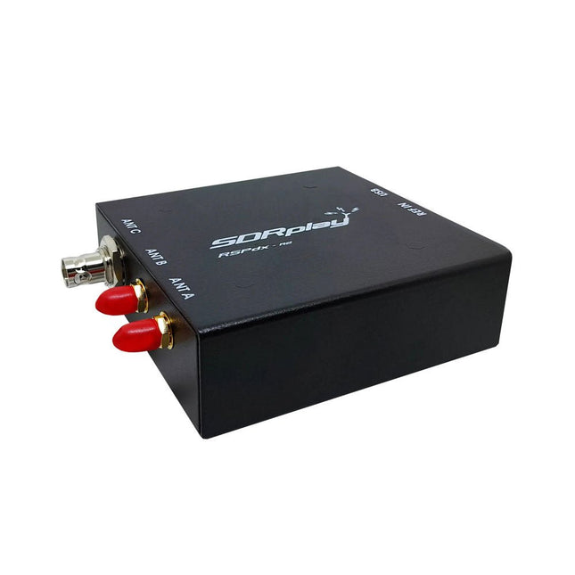
SDRplay SDRplay RSPdx-R2 Single-Tuner 14-bit SDR Receiver (1 kHz to 2 GHz)
The SDRplay RSPdx-R2 is a wideband full featured single-tuner 14-bit SDR receiver which covers the entire RF spectrum from 1 kHz to 2 GHz giving up to 10 MHz of spectrum visibility. It contains three antenna ports, two of which use SMA connectors and operate across the full 1 kHz to 2 GHz range and the third uses a BNC connector which operates up to 200 MHz. The RSPdx-R2 is an enhanced version of the RSPdx with further design improvements for use at frequencies below 2 MHz. Housed in a strong steel case, in addition to the functionality of the RSP1B, the RSPdx-R2 provides three software selectable antenna inputs and an external clock input. It offers excellent performance through HF and VHF frequencies all the way up to 2 GHz. The RSPdx-R2 also supports an "HDR mode" optimised for the demanding radio reception conditions below 2 MHz. The RSPdx-R2, when used in conjunction with SDRplay’s own software, introduces a special HDR (High Dynamic Range) mode for reception within selected bands below 2 MHz. HDR mode delivers improved intermodulation performance and fewer spurious responses for those challenging bands. Features Covers all frequencies from 1 kHz through VLF, LF, MW, HF, VHF, UHF and L-band to 2 GHz, with no gaps Receive, monitor and record up to 10 MHz of spectrum at a time Significantly improved noise performance below 1 MHz (i.e. for some MF, LF and below) Improved dynamic range below 2 MHz both in tuner mode and HDR mode HDR mode below 2 MHz giving overall dynamic range and selectivity advantages Software selectable choice of 3 antenna ports External clock input for synchronisation purposes, or connection to GPS reference clock for extra frequency accuracy Excellent dynamic range for challenging reception conditions Free use of Windows-based SDRuno software (check website for versions supported) Free use of SDRconnect SDR and server software for Windows, MacOS and Linux (Check website for versions supported) Multiplatform driver and API support including Windows, Linux, Mac and Raspberry Pi 4/5 Strong and growing software support network Calibrated S meter/RF power and SNR measurement with SDRuno (including datalogging to .CSV file capability) Documented API provided to allow demodulator or application development on multiple platforms Applications (Amateur) Shortwave radio listening Broadcast DXing (AM/FM/TV) Panadaptor Aircraft (ADS-B and ATC) Slow Scan TV Multi-amateur band monitoring WSPR & digital modes Weather fax (HF and satellite) Satellite monitoring Geostationary environmental satellites Trunked radio Utility and emergency service monitoring Fast and effective antenna comparison Applications (Industrial) Spectrum Analyser Surveillance Wireless microphone monitoring RF surveying IoT receiver chain Signal logging RFI/EMC detection Broadcast integrity monitoring Spectrum monitoring Power measurement Applications (Educational/Scientific) Teaching Receiver design Radio astronomy Passive radar Ionosonde Spectrum analyser Receiver for IoT sensor projects Antenna research Specifications Frequency Range 1 kHz – 2 GHz Antenna Connector SMA Antenna Impedance 50 Ohms Current Consumption (Typical) 190 mA @ >60 MHz (excl. Bias-T)120 mA @ <60 MHz (excl. Bias-T) USB Connector USB-B Maximum Input Power +0 dBm Continuous+10 dBm Short Duration ADC Sample Rates 2-10.66 MSPS ADC Number of Bits 14 bit 2-6.048 MSPS12 bit 6.048-8.064 MSPS10 bit 8.064-9.216 MSPS8 bit >9.216 MSPS Bias-T 4.7 V100 mA guaranteed Reference 0.5ppm 24 MHz TCXOFrequency error trimmable to 0.01ppm in field Operating Temperature −10˚C to +60˚C Dimensions 113 x 94 x 35 mm Weight 315 g Downloads Datasheet Software RSPdx-R2 vs RSPduo RSPdx-R2 RSPduo Continuous coverage from 1 kHz to 2 GHz ✓ ✓ Up to 10 MHz visible bandwidth ✓ ✓ 14-bit ADC silicon technology plus multiple high-performance input filters ✓ ✓ Software selectable AM/FM & DAB broadcast band notch filters ✓ ✓ 4.7 V Bias-T for powering external remote antenna amplifier ✓ ✓ Powers over the USB cable with a simple type B socket ✓ ✓ 50Ω SMA antenna input(s) for 1 kHz to 2 GHz operation (software selectable) 2 2 Additional software selectable Hi-Z input for up to 30 Mhz operation ✓ Additional software selectable 50Ω BNC input for up to 200 MHz operation ✓ Additional LF/VLF filter for below 500 kHz ✓ 24 MHz reference clock input (+ output on RSPduo) ✓ ✓ Dual tuners enabling reception on 2 totally independent 2 MHz ranges ✓ Dual tuners enabling diversity reception using SDRuno ✓ Rugged black painted steel case ✓ ✓ Overall performance below 2 MHz for MW and LF ++ + Multiple simultaneous applications + ++ Performance in challenging fading conditions (*using diversity tuning) + *++
€ 263,00
-
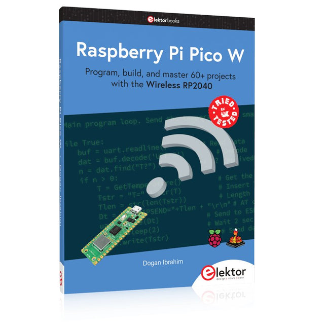
Elektor Publishing Raspberry Pi Pico W (Book)
Program, build, and master 60+ projects with the Wireless RP2040 The Raspberry Pi Pico and Pico W are based on the fast, efficient, and low-cost dual-core ARM Cortex M0+ RP2040 microcontroller chip running at up to 133 MHz and sporting 264 KB of SRAM and 2 MB of Flash memory. Besides spacious memory, the Pico and Pico W offer many GPIO pins, and popular peripheral interface modules like ADC, SPI, I²C, UART, PWM, timing modules, a hardware debug interface, and an internal temperature sensor. The Raspberry Pi Pico W additionally includes an on-board Infineon CYW43439 Bluetooth and Wi-Fi chipset. At the time of writing this book, the Bluetooth firmware was not yet available. Wi-Fi is however fully supported at 2.4 GHz using the 802.11b/g/n protocols. This book is an introduction to using the Raspberry Pi Pico W in conjunction with the MicroPython programming language. The Thonny development environment (IDE) is used in all of the 60+ working and tested projects covering the following topics: Installing the MicroPython on Raspberry Pi Pico using a Raspberry Pi or a PC Timer interrupts and external interrupts Analogue-to-digital converter (ADC) projects Using the internal temperature sensor and external sensor chips Using the internal temperature sensor and external temperature sensor chips Datalogging projects PWM, UART, I²C, and SPI projects Using Bluetooth, WiFi, and apps to communicate with smartphones Digital-to-analogue converter (DAC) projects All projects are tried & tested. They can be implemented on both the Raspberry Pi Pico and Raspberry Pi Pico W, although the Wi-Fi-based subjects will run on the Pico W only. Basic programming and electronics experience are required to follow the projects. Brief descriptions, block diagrams, detailed circuit diagrams, and full MicroPython program listings are given for all projects.
€ 44,95
Best Price
-
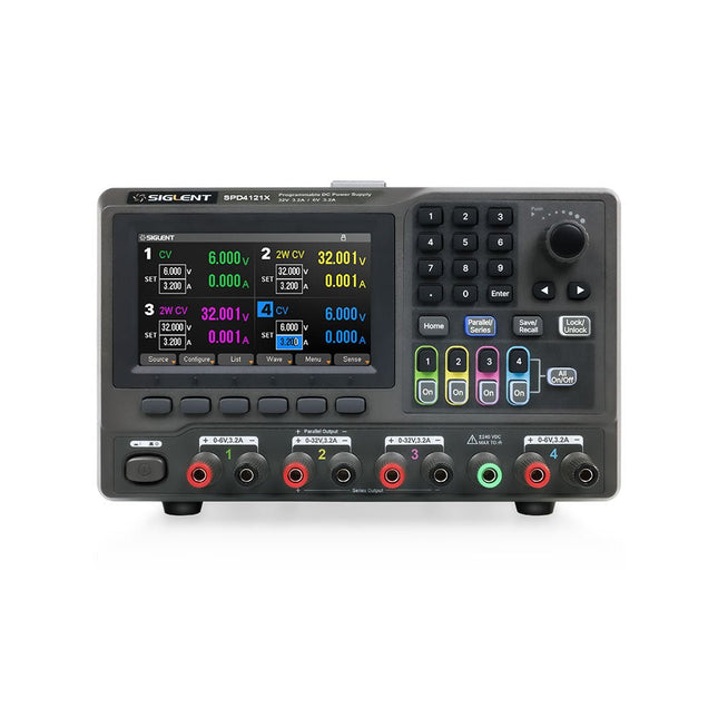
Siglent Siglent SPD4121X 4-ch DC Power Supply (285 W)
The Siglent SPD4121X is a 4-channel DC Linear Programmable Power Supply equipped with a 4.3-inch TFT-LCD display, friendly human-machine interface, and excellent performance indicators. Real-time waveform display provides engineers with an informative user interface. SPD4121X offers a total output power of 285 W with a resolution of 1 mV/1 mA. The maximum voltage and current for each channel are as follows: CH1: 15 V/1.5 A CH2: 12 V/10 A CH3: 12 V/10 A CH4: 15 V/1.5 A Features Rated output power: 285 W Rated voltage: 32 V, 12 V, 30 V Up to four high-precision power supplies with independent controllable outputs, supporting CH2 and CH3 series and parallel connections Clear graphical interface with waveform and timer display modes 5-digit voltage and current display with minimum resolution of 1 mV, 1 mA Fast output response time: <50us The high current channel support remote voltage compensation sense function. The maximum compensation voltage is 0.6 V Overvoltage protection and overcurrent protection or safe and accurate operation Equipped with a 4.3-inch TFT-LCD display (480 x 272 resolution) USB and LAN standard communication USB-GPIB module is optional Excellent channel density with up to 4 channels in a 3U half rack package Internal data storage for setups and parameters Embedded Web Server with instrument communication that doesn’t require software installation Fully SCPI programming command set support as well as a LabView driver for remote control and system automation Specifications SPD4323X SPD4121X SPD4306X Channel Output CH1: Voltage 0 to 6 V Current 0 to 3.2 ACH2: Voltage 0 to 32 V Current 0 to 3.2 ACH3: Voltage 0 to 32 V Current 0 to 3.2 ACH4: Voltage 0 to 6 V Current 0 to 3.2 A CH1: Voltage 0 to 15 V Current 0 to 1.5 ACH2: Voltage 0 to 12 V Current 0 to 10 ACH3: Voltage 0 to 12 V Current 0 to 10 ACH4: Voltage 0 to 15 V Current 0 to 1.5 A CH1: Voltage 0 to 15 V Current 0 to 1.5 ACH2: Voltage 0 to 30 V Current 0 to 6 ACH3: Voltage 0 to 30 V Current 0 to 6 ACH4: Voltage 0 to 15 V Current 0 to 1 A Resolution 1 mV, 1 mA 1 mV, 1 mA 1 mV, 1 mA Setting Accuracy Voltage: ±(0.03% of reading+10) mV, Current: ±(0.3% of reading+10) mA Voltage: ±(0.03% of reading+10) mV, Current: ±(0.3% of reading+10) mA Voltage: ±(0.03% of reading+10) mV, Current: ±(0.3% of reading+10) mA Readback Accuracy Voltage: ±(0.03% of reading+10) mV, Current: ±(0.3% of reading+10) mA Voltage: ±(0.03% of reading+10) mV, Current: ±(0.3% of reading+10) mA Voltage: ±(0.03% of reading+10) mV, Current: ±(0.3% of reading+10) mA Display 4.3" TFT-LCD 5-digit voltage and current display 4.3" TFT-LCD 5-digit voltage and current display 4.3" TFT-LCD 5-digit voltage and current display Output power 240 W 285 W 400 W Included 1x Siglent SPD4121X Power Supply 1x Power cord (EU) 1x Output test cord (3 A) 1x USB cable 1x Quick start guide Downloads Datasheet Manual Quick start
€ 871,20
-

FNIRSI FNIRSI DLA-16/32 Plus Logic Analyzer (16/32 Channels)
The FNIRSI DLA Series combines high-performance USB 3.0 logic analysis with flexible multi-channel signal capture for debugging and analyzing digital circuits and embedded systems. The series is available in two versions: the DLA-16 Plus with 16 digital channels and the DLA-32 Plus with 32 digital channels. Both models offer sampling rates of up to 1 GSa/s, 4 Gbit of onboard memory, and support for 120+ protocol decoders. With Buffer, Stream, and Roll acquisition modes, they are suitable for both high-speed signal analysis and long-term monitoring. Choose the DLA-16 Plus for higher sampling rates when using all channels, or the DLA-32 Plus when you need more channels and advanced serial and parallel triggering. Features Available with 16 or 32 digital input channels Up to 1 GSa/s sampling rate DLA-16 Plus: up to 500 MSa/s with all 16 channels DLA-32 Plus: up to 250 MSa/s with all 32 channels 4 Gbit onboard memory High-speed USB 3.0 interface Acquisition modes: Buffer, Stream, and Roll Support for 120+ protocol decoders Advanced triggering options 4 PWM outputs with 1 Hz–20 MHz frequency range CSV and BIN data export Specifications DLA-16 Plus DLA-32 Plus Digital Channels 16 32 Max. Sampling Rate 1 GSa/s Sampling Rate (1 Channel) 1 GSa/s Sampling Rate (8 Channels) 1 GSa/s Max. Buffer Sampling 16 CH @ 500 MSa/s 32 CH @ 250 MSa/s Max. Stream Sampling 16 CH @ 125 MSa/s 32 CH @ 50 MSa/s Hardware Memory 4 Gbit Interface USB 3.0 / USB-C Max. USB Transfer Rate 5 Gbit/s Acquisition Modes Buffer / Stream / Roll Protocol Decoders 120+ Custom Protocol Support Yes Trigger Modes Rising Edge, Falling Edge, High, Low, Any Edge Advanced Trigger Standard Triggering Serial and Parallel Parallel Trigger Stages – Up to 16 PWM Outputs 4 PWM Output Voltage 3.3 V PWM Frequency 1 Hz–20 MHz Data Export CSV, BIN Dimensions 90 x 81 x 11.5 mm Included 1x FNIRSI DLA-16/32 Plus Logic Analyzer 4 Sets x 5 Shielded Cables 18x Mini IC Test Hooks (High Configuration Version) 1x USB 3.0 Data Cable 10x IC Test Hooks 1x Transparent Storage Case for Test Hooks 1x Storage Bag 1x Manual Downloads Manual Software for Windows Software for macOS (Apple Silicon) Software for macOS (Intel)


