
Search results for "mixer OR geek OR theremin OR musical OR instrument"
-

Elektor Digital Experimenting with Red Pitaya STEMlab Gen 2 (E-book)
Practical Projects and Programs With Experimenting with Red Pitaya STEMlab Gen 2, Red Pitaya goes beyond a versatile board. It becomes a powerful laboratory instrument for precision measurement, analysis, and control. From the fundamentals of electronic project development, monitoring, control, and design to testing, this book walks you step-by-step through everything you need to know to harness the full potential of Red Pitaya hardware and software. The book presents real-time, FPGA-based projects that are developed on a PC using the Vivado environment, then transferred to the Red Pitaya for execution and testing. You will learn about enhanced performance, expanded I/O capabilities, improved FPGA features, and advanced connectivity options that open up new frontiers for precision measurement, monitoring, and control in your embedded applications. Inside the book you will discover: A deep dive into Red Pitaya architecture and hardware design Electronic experiments using Red Pitaya for measurement and monitoring Hands-on projects using the Python programming language Practical guidance for FPGA programming using Red Pitaya Red Pitaya FPGA projects using the Verilog HDL under Vivado IDE Practical design of electronic projects including measurement and testing Step-by-step examples that bridge theory and real-world implementation Whether you are designing your own electronic circuits, developing signal analysis tools, or creating real-time control or monitoring systems, this book provides you the knowledge and confidence you need to fully learn and customize the Red Pitaya platform.
€ 32,95
Members: € 29,66
-

Elektor November/December 2025 (EN)
Elektor GREEN and GOLD members can download their digital edition here. Not a member yet? Click here. Relio v1.0 - Presence Detection and Remote ControlA Matter-Enabled Smart Controller for AC Appliances Designing Better PCBsA Practical Guide for Professionals and Makers KiCad 9Top New and Updated Features Precision Picoammeter (1)With Curve Tracer Functionality Down to the pA range! Christmas Star 2025A Star Is Soldered 100 mV Continuity Tester Who’s Pushing the Boundaries of European Electronics?Companies to Watch productronica 2025: What’s New in Electronics Development and Production Automation to Tackle Reshoring Manufacturing, Tariffs and Labour Shortages Beyond Future ProofCircularity in Electronics Passive ComponentsLow-Loss Inductors Enabling High-Efficiency DC/DC Converters How Desktop Manufacturing Machines Are Democratizing PCB Production Starting Out in Electronics...Needs Power UHD Displays Driven with EaseYour Guide to Easily Put Various TFT-LCDs Into Operation Quickly Soldering in 2025Practical Soldering Tips Straight from the Workbench SimulIDEAn All-in-One Tool for Circuit Prototyping 2025: An AI OdysseyFrom Autocomplete to Colleague Wordy Christmas TreeA Festive Electronics Project with a Linguistic Twist Err-lectronicsCorrections, Updates, and Readers’ Letters Analog Pipeline DistortionA Cool Audio Effect For Guitars and Other Instruments ESP32 Audio Transceiver Board (Part 3)Stereo Transmission and Dual Radio
€ 14,90
-

Elektor Digital Elektor 11-12/2025 (PDF) DE
Diese Ausgabe steht allen GOLD- und GREEN-Mitgliedern auf der ElektorMagazine-Website zum Download bereit! Sie sind noch kein Mitglied? Hier klicken! Relio v1.0 – Anwesenheitserkennung und FernsteuerungEin Matter-fähiger Smart-Controller für Hausgeräte Bessere Leiterplatten entwerfenEin praxisnaher Leitfaden für Profis und Maker KiCad 9Die wichtigsten neuen und aktualisierten Funktionen Präzisions-Picoamperemeter (Teil 1)Mit Kennlinienschreiber-Funktion bis in den pA-Bereich Analoger Pipeline-VerzerrerEin cooler Audioeffekt für Gitarren und andere Instrumente Halogene in LötmittelnFakten statt Mythen 100-mV-Durchgangsprüfer Wer treibt die europäische Elektronik voran?Unternehmen im Fokus productronica 2025Neuheiten in Elektronikentwicklung und -fertigung Automatisierung bewältigt Herausforderungenwie Reshoring, Zölle und Arbeitskräftemangel Mehr als ZukunftssicherheitKreislaufwirtschaft in der Elektronik Passive BauelementeVerlustarme Induktivitäten für hocheffiziente DC/DC-Wandler PCB-Produktion im WandelDesktop-Maschinen eröffnen neue Wege für die Leiterplattenfertigung Aller Anfang ...... braucht Spannung UHD-Displays mühelos ansteuernIhr Leitfaden, um unterschiedliche TFT-LCDs schnell in Betrieb zu nehmen Löten im Jahr 2025Praktische Tipps direkt von der Werkbank Weihnachtsstern 2025Ein Stern wird gelötet SimulIDEEin All-in-One-Werkzeug für die Schaltungsentwicklung 2025: Eine KI-OdysseeVom Autovervollständiger zum Kollegen Wortreicher WeihnachtsbaumEin festliches Elektronikprojekt mit verbalem Highlight Projekt 2.0Korrekturen, Updates und Leserbriefe ESP32-Audio-Transceiver-Board (Teil 3)Stereosender und Dual Radio
€ 11,90
-
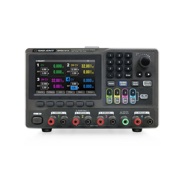
Siglent Siglent SPD4121X 4-ch DC Power Supply (285 W)
The Siglent SPD4121X is a 4-channel DC Linear Programmable Power Supply equipped with a 4.3-inch TFT-LCD display, friendly human-machine interface, and excellent performance indicators. Real-time waveform display provides engineers with an informative user interface. SPD4121X offers a total output power of 285 W with a resolution of 1 mV/1 mA. The maximum voltage and current for each channel are as follows: CH1: 15 V/1.5 A CH2: 12 V/10 A CH3: 12 V/10 A CH4: 15 V/1.5 A Features Rated output power: 285 W Rated voltage: 32 V, 12 V, 30 V Up to four high-precision power supplies with independent controllable outputs, supporting CH2 and CH3 series and parallel connections Clear graphical interface with waveform and timer display modes 5-digit voltage and current display with minimum resolution of 1 mV, 1 mA Fast output response time: <50us The high current channel support remote voltage compensation sense function. The maximum compensation voltage is 0.6 V Overvoltage protection and overcurrent protection or safe and accurate operation Equipped with a 4.3-inch TFT-LCD display (480 x 272 resolution) USB and LAN standard communication USB-GPIB module is optional Excellent channel density with up to 4 channels in a 3U half rack package Internal data storage for setups and parameters Embedded Web Server with instrument communication that doesn’t require software installation Fully SCPI programming command set support as well as a LabView driver for remote control and system automation Specifications SPD4323X SPD4121X SPD4306X Channel Output CH1: Voltage 0 to 6 V Current 0 to 3.2 ACH2: Voltage 0 to 32 V Current 0 to 3.2 ACH3: Voltage 0 to 32 V Current 0 to 3.2 ACH4: Voltage 0 to 6 V Current 0 to 3.2 A CH1: Voltage 0 to 15 V Current 0 to 1.5 ACH2: Voltage 0 to 12 V Current 0 to 10 ACH3: Voltage 0 to 12 V Current 0 to 10 ACH4: Voltage 0 to 15 V Current 0 to 1.5 A CH1: Voltage 0 to 15 V Current 0 to 1.5 ACH2: Voltage 0 to 30 V Current 0 to 6 ACH3: Voltage 0 to 30 V Current 0 to 6 ACH4: Voltage 0 to 15 V Current 0 to 1 A Resolution 1 mV, 1 mA 1 mV, 1 mA 1 mV, 1 mA Setting Accuracy Voltage: ±(0.03% of reading+10) mV, Current: ±(0.3% of reading+10) mA Voltage: ±(0.03% of reading+10) mV, Current: ±(0.3% of reading+10) mA Voltage: ±(0.03% of reading+10) mV, Current: ±(0.3% of reading+10) mA Readback Accuracy Voltage: ±(0.03% of reading+10) mV, Current: ±(0.3% of reading+10) mA Voltage: ±(0.03% of reading+10) mV, Current: ±(0.3% of reading+10) mA Voltage: ±(0.03% of reading+10) mV, Current: ±(0.3% of reading+10) mA Display 4.3" TFT-LCD 5-digit voltage and current display 4.3" TFT-LCD 5-digit voltage and current display 4.3" TFT-LCD 5-digit voltage and current display Output power 240 W 285 W 400 W Included 1x Siglent SPD4121X Power Supply 1x Power cord (EU) 1x Output test cord (3 A) 1x USB cable 1x Quick start guide Downloads Datasheet Manual Quick start
€ 871,20
-
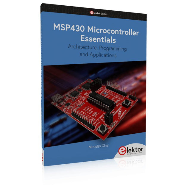
Elektor Publishing MSP430 Microcontroller Essentials
Architecture, Programming and Applications The MSP430 is a popular family of microcontrollers from Texas Instruments. In this book we will work with the smallest type, which is the powerful MSP430G2553. We will look at the capabilities of this microcontroller in detail, as it is well-suited for self-made projects because it is available in a P-DIP20 package. We will take a closer look at the microcontroller and then build, step by step, some interesting applications, including a 'Hello World' blinking LED and a nice clock application, which can calculate the day of the week based on the date. You also will learn how to create code for the MSP microcontroller in assembler. In addition to that, we will work with the MSP-Arduino IDE, which makes it quite easy to create fast applications without special in-depth knowledge of the microcontrollers. All the code used in the book is available for download from the Elektor website.
€ 39,95
Members: € 35,96
-
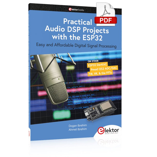
Elektor Digital Practical Audio DSP Projects with the ESP32 (E-book)
Easy and Affordable Digital Signal ProcessingThe aim of this book is to teach the basic principles of Digital Signal Processing (DSP) and to introduce it from a practical point of view using the bare minimum of mathematics. Only the basic level of discrete-time systems theory is given, sufficient to implement DSP applications in real time. The practical implementations are described in real time using the highly popular ESP32 DevKitC microcontroller development board. With the low cost and extremely popular ESP32 microcontroller, you should be able to design elementary DSP projects with sampling frequencies within the audio range. All programming is done using the popular Arduino IDE in conjunction with the C language compiler.After laying a solid foundation of DSP theory and pertinent discussions on the main DSP software tools on the market, the book presents the following audio-based sound and DSP projects: Using an I²S-based digital microphone to capture audio sound Using an I²S-based class-D audio amplifier and speaker Playing MP3 music stored on an SD card through an I²S-based amplifier and speaker Playing MP3 music files stored in ESP32 flash memory through an I²S-based amplifier and speaker Mono and stereo Internet radio with I²S-based amplifiers and speakers Text-to-speech output with an I²S-based amplifier and speaker Using the volume control in I²S-based amplifier and speaker systems A speaking event counter with an I²S-based amplifier and speaker An adjustable sinewave generator with I²S-based amplifier and speaker Using the Pmod I²S2 24-bit fast ADC/DAC module Digital low-pass and band-pass real-time FIR filter design with external and internal A/D and D/A conversion Digital low-pass and band-pass real-time IIR filter design with external and internal A/D and D/A conversion Fast Fourier Transforms (FFT)
€ 32,95
Members: € 29,66
-
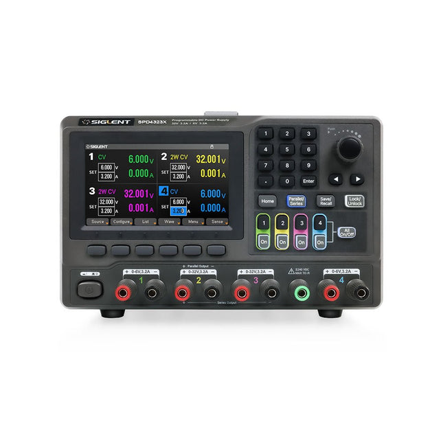
Siglent Siglent SPD4323X 4-ch DC Power Supply (240 W)
The Siglent SPD4323X is a 4-channel DC Linear Programmable Power Supply equipped with a 4.3-inch TFT-LCD display, friendly human-machine interface, and excellent performance indicators. Real-time waveform display provides engineers with an informative user interface. SPD4323X offers a total output power of 240 W with a resolution of 1 mV/1 mA. The maximum voltage and current for each channel are as follows: CH1: 6 V/3.2 A CH2: 32 V/3.2 A CH3: 32 V/3.2 A CH4: 6 V/3.2 A Features Rated output power: 240 W Rated voltage: 32 V, 12 V, 30 V Up to four high-precision power supplies with independent controllable outputs, supporting CH2 and CH3 series and parallel connections Clear graphical interface with waveform and timer display modes 5-digit voltage and current display with minimum resolution of 1 mV, 1 mA Fast output response time: <50us The high current channel support remote voltage compensation sense function. The maximum compensation voltage is 0.6 V Overvoltage protection and overcurrent protection or safe and accurate operation Equipped with a 4.3-inch TFT-LCD display (480 x 272 resolution) USB and LAN standard communication USB-GPIB module is optional Excellent channel density with up to 4 channels in a 3U half rack package Internal data storage for setups and parameters Embedded Web Server with instrument communication that doesn’t require software installation Fully SCPI programming command set support as well as a LabView driver for remote control and system automation Specifications SPD4323X SPD4121X SPD4306X Channel Output CH1: Voltage 0 to 6 V Current 0 to 3.2 ACH2: Voltage 0 to 32 V Current 0 to 3.2 ACH3: Voltage 0 to 32 V Current 0 to 3.2 ACH4: Voltage 0 to 6 V Current 0 to 3.2 A CH1: Voltage 0 to 15 V Current 0 to 1.5 ACH2: Voltage 0 to 12 V Current 0 to 10 ACH3: Voltage 0 to 12 V Current 0 to 10 ACH4: Voltage 0 to 15 V Current 0 to 1.5 A CH1: Voltage 0 to 15 V Current 0 to 1.5 ACH2: Voltage 0 to 30 V Current 0 to 6 ACH3: Voltage 0 to 30 V Current 0 to 6 ACH4: Voltage 0 to 15 V Current 0 to 1 A Resolution 1 mV, 1 mA 1 mV, 1 mA 1 mV, 1 mA Setting Accuracy Voltage: ±(0.03% of reading+10) mV, Current: ±(0.3% of reading+10) mA Voltage: ±(0.03% of reading+10) mV, Current: ±(0.3% of reading+10) mA Voltage: ±(0.03% of reading+10) mV, Current: ±(0.3% of reading+10) mA Readback Accuracy Voltage: ±(0.03% of reading+10) mV, Current: ±(0.3% of reading+10) mA Voltage: ±(0.03% of reading+10) mV, Current: ±(0.3% of reading+10) mA Voltage: ±(0.03% of reading+10) mV, Current: ±(0.3% of reading+10) mA Display 4.3" TFT-LCD 5-digit voltage and current display 4.3" TFT-LCD 5-digit voltage and current display 4.3" TFT-LCD 5-digit voltage and current display Output power 240 W 285 W 400 W Included 1x Siglent SPD4323X Power Supply 1x Power cord (EU) 1x Output test cord (3 A) 1x USB cable 1x Quick start guide Downloads Datasheet Manual Quick start
€ 762,30
-
Siglent Siglent SPD4306X 4-ch DC Power Supply (400 W)
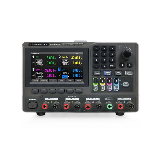
The Siglent SPD4306X is a 4-channel DC Linear Programmable Power Supply equipped with a 4.3-inch TFT-LCD display, friendly human-machine interface, and excellent performance indicators. Real-time waveform display provides engineers with an informative user interface. SPD4306X offers a total output power of 400 W with a resolution of 1 mV/1 mA. The maximum voltage and current for each channel are as follows: CH1: 15 V/1.5 A CH2: 30 V/6 A CH3: 30 V/6 A CH4: 15 V/1 A Features Rated output power: 400 W Rated voltage: 32 V, 12 V, 30 V Up to four high-precision power supplies with independent controllable outputs, supporting CH2 and CH3 series and parallel connections Clear graphical interface with waveform and timer display modes 5-digit voltage and current display with minimum resolution of 1 mV, 1 mA Fast output response time: <50us The high current channel support remote voltage compensation sense function. The maximum compensation voltage is 0.6 V Overvoltage protection and overcurrent protection or safe and accurate operation Equipped with a 4.3-inch TFT-LCD display (480 x 272 resolution) USB and LAN standard communication USB-GPIB module is optional Excellent channel density with up to 4 channels in a 3U half rack package Internal data storage for setups and parameters Embedded Web Server with instrument communication that doesn’t require software installation Fully SCPI programming command set support as well as a LabView driver for remote control and system automation Specifications SPD4323X SPD4121X SPD4306X Channel Output CH1: Voltage 0 to 6 V Current 0 to 3.2 ACH2: Voltage 0 to 32 V Current 0 to 3.2 ACH3: Voltage 0 to 32 V Current 0 to 3.2 ACH4: Voltage 0 to 6 V Current 0 to 3.2 A CH1: Voltage 0 to 15 V Current 0 to 1.5 ACH2: Voltage 0 to 12 V Current 0 to 10 ACH3: Voltage 0 to 12 V Current 0 to 10 ACH4: Voltage 0 to 15 V Current 0 to 1.5 A CH1: Voltage 0 to 15 V Current 0 to 1.5 ACH2: Voltage 0 to 30 V Current 0 to 6 ACH3: Voltage 0 to 30 V Current 0 to 6 ACH4: Voltage 0 to 15 V Current 0 to 1 A Resolution 1 mV, 1 mA 1 mV, 1 mA 1 mV, 1 mA Setting Accuracy Voltage: ±(0.03% of reading+10) mV, Current: ±(0.3% of reading+10) mA Voltage: ±(0.03% of reading+10) mV, Current: ±(0.3% of reading+10) mA Voltage: ±(0.03% of reading+10) mV, Current: ±(0.3% of reading+10) mA Readback Accuracy Voltage: ±(0.03% of reading+10) mV, Current: ±(0.3% of reading+10) mA Voltage: ±(0.03% of reading+10) mV, Current: ±(0.3% of reading+10) mA Voltage: ±(0.03% of reading+10) mV, Current: ±(0.3% of reading+10) mA Display 4.3" TFT-LCD 5-digit voltage and current display 4.3" TFT-LCD 5-digit voltage and current display 4.3" TFT-LCD 5-digit voltage and current display Output power 240 W 285 W 400 W Included 1x Siglent SPD4306X Power Supply 1x Power cord (EU) 1x Output test cord (3 A) 1x USB cable 1x Quick start guide Downloads Datasheet Manual Quick start
€ 1.101,10
-
Elektor Digital The State of Hollow State Audio (E-book)
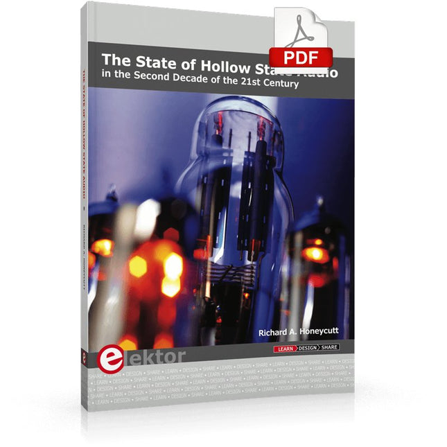
The State of Hollow State Audio in the Second Decade of the 21st Century Vacuum-tube (or valve, depending upon which side of the pond you live on) technology spawned the Age of Electronics early in the 20th Century. Until the advent of solid-state electronics near mid-century, hollow-state devices were the only choice. But following the invention of the transistor (after their process fell to reasonable levels), within a couple of decades, the death of vacuum tubes was widely heralded. Yet here we are some five decades later, and hollow-state equipment is enjoying something of a comeback, especially in the music and high-end audio industries. Many issues surround hollow-state audio: Does it produce—as some claim—better sound? If so, is there science to back up these claims? How do hollow-state circuits work? How do you design hollow-state audio circuits? If hollow-state equipment fails, how do you go about troubleshooting and repairing it? Can we recreate some of the classic hollow-state audio devices for modern listening rooms and recording studios? How can we intelligently modify hollow-state amplifiers to our taste? These and other topics are covered in The State of Hollow State Audio.
€ 32,95
Members: € 29,66
-

QuantAsylum QuantAsylum QA403 24-bit Audio Analyzer
The QA403 is QuantAsylum's fourth-generation audio analyzer. The QA403 extends the functionality of the QA402 with improved noise and distortion performance, in addition to a flatter response at band edges. The compact size of the QA403 means you can take it just about anywhere. Features 24-bit ADC/DAC Up to 192 kS/s Fully isolated from PC Differential Input/Output USB powered Built-in Attenuator Fast Bootup and Driverless The QA403 is a driverless USB device, meaning it’s ready as soon as you plug it in. The software is free and it is quick and easy to move the hardware from one machine to the next. So, if you need to head to the factory to troubleshoot a problem or take the QA403 home for a work-from-home day, you can do it without hassle. No-Cal Design The QA403 comes with a factory calibration in its flash memory, ensuring consistent unit-to-unit performance. On your manufacturing line you can install another QA403 and be confident what you read on one unit will be very similar to the next unit. It is not expected that re-calibration will be required at regular intervals. Measurements Making basic measurements is quick and easy. In a few clicks you will understand the frequency response, THD(+N), gain, SNR and more of your device-under test. Dynamic Range The QA403 offers 8 gain ranges on the input (0 to +42 dBV in 6 steps), and 4 gain ranges on the output (-12 to +18 dBV in 10 dB steps). This ensures consistent performance over very wide ranges of input and output levels. The maximum AC input to the QA403 is +32 dBV = 40 Vrms. The maximum DC is ±40 V, and the maximum ACPEAK + DC = ±56 V. Easy Programmability The QA403 supports a REST interface, making it easy to automate measurements in just about any language you might anticipate. From Python to C++ to Visual Basic—if you know how to load a web page in your favorite language, you can control the QA403 remotely. Measurements are fast and responsive, usually with dozens of commands being processed per second. Isolated and USB Powered The QA403 is isolated from the PC, meaning you are measuring your DUT and not chasing some phantom ground loop. The QA403 is USB powered, like nearly all our instruments. If you are setting up remotely, throw a powered hub in your bag and your entire test setup can be running with a minimum of cables. Goodbye Soundcard, Hello QA403 Tired of trying to make a soundcard work? The calibration nightmare? The lack of gain stages? The limited drive? Are you tired of dealing with the fixed input ranges? The worry that you might destroy it with too much DC or AC? Tired of the ground loops? That’s why QuantAsylum built the QA403. Specifications Case Material Powder-coating Aluminum (2 mm thick front panel, 1.6 mm thick top/bottom) Dimensions 177 x 44 x 97 mm (W x H x D) Weight 435 g Downloads Datasheet Manual GitHub
-

Elektor Labs Elektor Dual DC LISN (150 kHz – 200 MHz)
Measuring conducted emission is the simplest and most affordable method of getting some indication of whether a design can meet EMI/EMC requirements. A Line Impedance Stabilization Network (LISN) is an indispensable part of an EMC pre-compliance test setup. In cooperation with Würth Elektronik, Elektor has developed a 5 µH, 50 Ω Dual DC LISN that supports voltages up to 60 V and currents up to 10 A. The instrument measures RF interferences on both channels (the power supply) by means of 5-μH blocking inductances. The internal 10-dB attenuation network – one in each channel – contains a 3rd-order high-pass filter with a cutoff frequency of 9 kHz to protect the input of instruments like a spectrum analyzer from potentially harmful DC voltages or low frequencies coming from the EUT (Equipment Under Test). Specifications RF path Channels 2 (with clamping diodes) Bandwidth 150 kHz – 200 MHz Inductance 5 μH || 50 Ω Internal attenuation 10 dB Connectors SMA DC path Max. current < 10 ADC Max. voltage < 60 VDC DC resistance < 2 x 70 mΩ PCB size 94.2 x 57.4 mm Connectors 4-mm banana Hammond enclosure Type 1590N Dimensions 121 x 66 x 40 mm Included 1x 4-layer PCB with all SMT parts fitted 1x pre-drilled enclosure with ready-printed front panel layout 5x gold-plated, insulated, 4-mm banana sockets, rated for 24 A, 1 kV 1x Hammond enclosure 1590N1, Aluminum (Die-Cast Alloy) More Info Project on Elektor Labs: Dual DC LISN for EMC pre-compliance testing Elektor 9-10/2021: EMC Pre-Compliance Test for Your DC-Powered Project (Part 1) Elektor 11-12/2021: EMC Pre-Compliance Test for Your DC-Powered Project (Part 2)
-
Elektor Bundles Raspberry Pi 5 RTL-SDR V4 (Bundle)
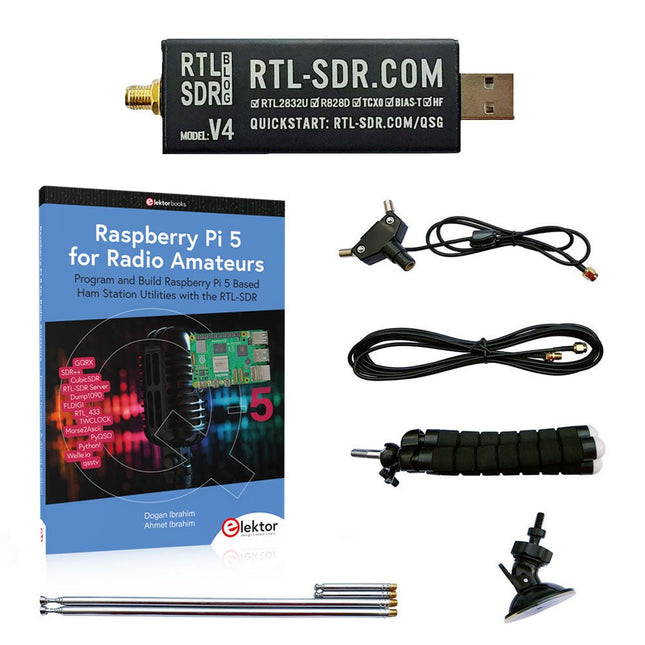
Program and build Raspberry Pi based ham station utilities, tools, and instruments The improved RTL-SDR V4 allows you to receive radio signals between 500 kHz and 1.75 GHz from stations utilizing different bands including MW/SW/LW broadcast, ham radio, utility, air traffic control, PMR, SRD, ISM, CB, weather satellite, and radio astronomy. The book Raspberry Pi 5 for Radio Amateurs gives extensive coverage of deploying the RTL-SDR kit through the use of a Raspberry Pi 5. This bundle contains: RTL-SDR V4 (incl. Dipole Antenna Kit) (normal price: €75) Raspberry Pi 5 for Radio Amateurs (normal price: €40) RTL-SDR V4 (Software Defined Radio) with Dipole Antenna Kit RTL-SDR is an affordable dongle that can be used as a computer-based radio scanner for receiving live radio signals between 500 kHz and 1.75 GHz in your area. The RTL-SDR V4 offers several improvements over generic brands including use of the R828D tuner chip, triplexed input filter, notch filter, improved component tolerances, a 1 PPM temperature compensated oscillator (TCXO), SMA F connector, aluminium case with passive cooling, bias tee circuit, improved power supply, and a built in HF upconverter. RTL-SDR V4 comes with the portable dipole antenna kit. It is great for beginners as it allows for terrestrial and satellite reception and easy to mount outdoors and designed for portable and temporary outside usage. Features Improved HF reception: V4 now uses a built-in upconverter instead of using a direct sampling circuit. This means no more Nyquist folding of signals around 14.4 MHz, improved sensitivity, and adjustable gain on HF. Like the V3, the lower tuning range remains at 500 kHz and very strong reception may still require front end attenuation/filtering. Improved filtering: The V4 makes use of the R828D tuner chip, which has three inputs. The SMA input has been triplexed input into 3 bands: HF, VHF and UHF. This provides some isolation between the 3 bands, meaning out of band interference from strong broadcast stations is less likely to cause desensitization or imaging. Improved filtering x2: In addition to the triplexing, the open drain pin on the R828D can be also used, which allows to add simple notch filters for common interference bands such as broadcast AM, broadcast FM and the DAB bands. These only attenuate by a few dB, but may still help. Improved phase noise on strong signals: Due to an improved power supply design, phase noise from power supply noise has been significantly reduced. Less heat: Another advantage of the improved power supply is low power consumption and less heat generation compared to the V3. Included 1x RTL-SDR V4 dongle (R828D RTL2832U 1PPM TCXO SMA) 2x 23 cm to 1 m telescopic antenna 2x 5 cm to 13 cm telescopic antenna 1x Dipole antenna base with 60 cm RG174 1x 3 m RG174 extension cable 1x Flexible tripod mount 1x Suction cup mount Downloads Datasheet User Guide Quick Start Guide SDR# User Guide Dipole Antenna Guide Book: Raspberry Pi 5 for Radio Amateurs The RTL-SDR devices (V3 and V4) have gained popularity among radio amateurs because of their very low cost and rich features. A basic system may consist of a USB based RTL-SDR device (dongle) with a suitable antenna, a Raspberry Pi 5 computer, a USB based external audio input-output adapter, and software installed on the Raspberry Pi 5 computer. With such a modest setup, it is possible to receive signals from around 24 MHz to over 1.7 GHz. This book is aimed at amateur radio enthusiasts and electronic engineering students, as well as at anyone interested in learning to use the Raspberry Pi 5 to build electronic projects. The book is suitable for both beginners through experienced readers. Some knowledge of the Python programming language is required to understand and eventually modify the projects given in the book. A block diagram, a circuit diagram, and a complete Python program listing is given for each project, alongside a comprehensive description. The following popular RTL-SDR programs are discussed in detail, aided by step-by-step installation guides for practical use on a Raspberry Pi 5: SimpleFM GQRX SDR++ CubicSDR RTL-SDR Server Dump1090 FLDIGI Quick RTL_433 aldo xcwcp GPredict TWCLOCK CQRLOG klog Morse2Ascii PyQSO Welle.io Ham Clock CHIRP xastir qsstv flrig XyGrib FreeDV Qtel (EchoLink) XDX (DX-Cluster) WSJT-X The application of the Python programming language on the latest Raspberry Pi 5 platform precludes the use of the programs in the book from working on older versions of Raspberry Pi computers.


