
Search results for "ft232r OR usb OR serial OR bridge OR bob OR 110553 OR 91"
-

FNIRSI FNIRSI HRM-10 Battery Internal Resistance & Voltage Tester
The FNIRSI HRM-10 is a portable, high-precision battery internal resistance and voltage tester. This device offers true four-wire measurement and is designed for both accuracy and ease of use. It automatically measures internal resistance and voltage values simultaneously, displaying the results on its HD color screen. Users have the option to manually adjust voltage and resistance ranges to suit their needs. The device also includes a sorting mode that automatically filters the good and bad batteries based on user-set thresholds. Additionally, it supports the storage of historical data and allows for exporting measurement records in table format. Features High Measurement Accuracy Tabular Data Export Auto-Evaluate Measurement Results 8 Threshold Settings HD Color Screen Folding Stand 1000 mAh Lithium Battery Specifications Voltage Resistance Measuring range 0-100 V (DC) 0-200 Ω Accuracy ±0.5% ±0.5% Gear Automatic, 1 V, 10 V, 100 V Automatic, 20 mΩ, 200 mΩ, 2 Ω, 20 Ω, 200 Ω Instrument test signal frequency 1 Khz (AC) Rechargeable USB-C (5 V/1 A) Built-in battery 1000 mAh lithium battery User calibration Yes Sorting mode Yes History record Yes Recorded data export Yes Working environment –10°C to +45°C, relative humidity <80% Storage environment –20°C to +80°C, relative humidity <80% Dimensions 158.7 x 80.5 x 28.4 mm Weight 225 g Included 1x FNIRSI HRM-10 Internal Resistance Tester 1x Clip Test Line 1x USB-C data cable 1x Manual Downloads Manual Firmware V0.3
€ 49,95
-
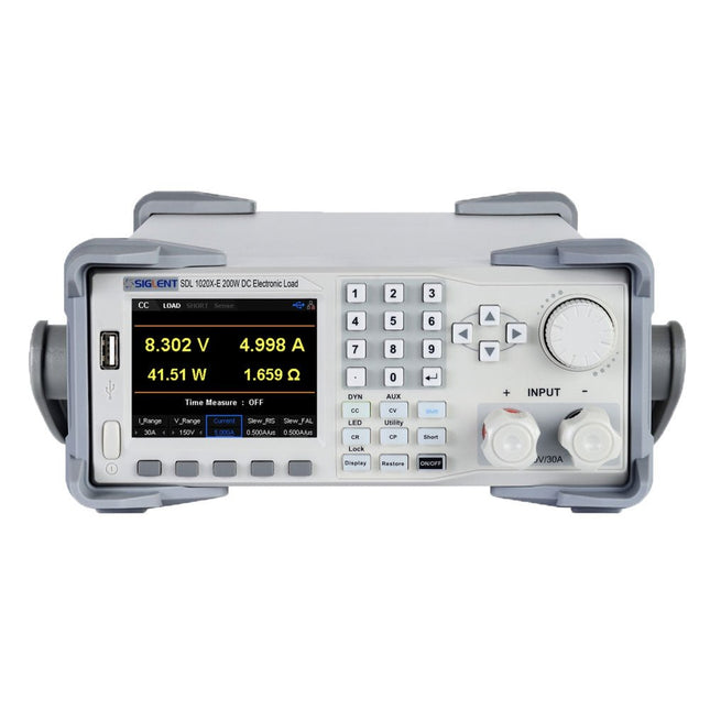
Siglent Siglent SDL1020X-E DC Electronic Load (200 W)
The Siglent SDL1020X-E DC Load leads with measurement resolution of 0.1 mV/0.1 mA and the base SDL1000X-E series resolution is 1 mV/1 mA and adjustable current rise times from 0.001 A/μs~2.5 A/μs. For remote communication and control, the SDL series includes S232/USB/LAN interface types. The SDL1020X-E delivers stability over a wide range of applications and can meet all kinds of testing requirements. including: Power, battery/handheld device design, industry, LED lighting, automotive electronics, and aerospace. Features SDL1020X-E (Single channel): DC 150 V/30 A, total power 200 W 4 static modes / Dynamic mode: CC/CV/CR/CP CC Dynamic mode: Continuous, pulsed, toggled CC Dynamic mode: 25 kHz, CP Dynamic mode: 12.5 kHz, CV Dynamic mode: 0.5 Hz Measuring speed of voltage and current: up to 500 kHz Adjustable current rise time range: 0.001 A/us~2.5 A/us Min. readback resolution: 0.1 mV, 0.1 mA Short-circuit, Battery test, CR-LED mode, and factory test functions 4-wire SENSE compensation mode function List function supports editing as many as 100 steps Program function supports 50 groups of steps OCP, OVP, OPP, OTP and LRV protection External analog control Voltage, Current monitoring via 0-10 V 3.5 inch TFT-LCD display, capable of displaying multiple parameters and states simultaneously Built-in RS232/USB/LAN communication interface, USB-GPIB module (optional) Waveform trend chart and easy-to-use file storage and call functions Includes PC software: Supports SCPI, LabView driver Included 1x Siglent SDL1020X-E DC Programmable Load 1x Quick start guide 1x Guarantee Card 1x Power Cord 1x USB Cable Downloads Datasheet Manual Programming Guide PC Software
€ 531,19
-

Elektor Bundles Elektor Raspberry Pi Pico Kit für Fortgeschrittene (Bundle)
Umfassendes Buch-Hardware-Bundle für den RP2040-Mikrocontroller mit über 80 Projekten Entdecken Sie in diesem Bundle das Potenzial der modernen Controller-Technologie mit dem Raspberry Pi Pico. Das leicht verständliche Handbuch eignet sich sowohl für Anfänger als auch für erfahrene Benutzer und führt Sie von den Grundlagen der Elektronik bis hin zu den komplexen Aspekten der digitalen Signalverarbeitung. Mit dem Raspberry Pi Pico, dem speziellen Hardware-Kit und der MicroPython-Programmierung lernen Sie die wichtigsten Prinzipien des Schaltungsdesigns, der Datenerfassung und -verarbeitung. Machen Sie praktische Erfahrungen mit über 80 Projekten wie einer Stoppuhr mit OLED-Display, einem Laser-Entfernungsmesser und einem servogesteuerten Lüfter. Diese Projekte sollen Ihnen helfen, das Gelernte in realen Szenarien anzuwenden. Das Buch behandelt auch fortgeschrittene Themen wie drahtlose RFID-Technologie, Objekterkennung und Sensorintegration für die Robotik. Ganz gleich, ob Sie Ihre Kenntnisse in der Elektronik erweitern oder tiefer in eingebettete Systeme eintauchen möchten, dieses Bundle ist die perfekte Ressource, um das volle Potenzial des Raspberry Pi Pico zu erkunden. Inhalt des Bundles 1x Projektbuch (287 Seiten) 1x Smart Car Kit Bauteile 2x Lötfreies Steckbrett (400 Löcher) 1x Lötfreies Steckbrett (170 Löcher) 5x bunte 5-mm-LEDs (Grün, Rot, Blau, Gelb und Weiß) 1x Lasersender 1x Passiver Summer 1x Micro-USB-Kabel (30 cm) 1x 65 Überbrückungskabel 1x 20 cm männlicher auf weiblicher Dupont-Draht 1x Transparentes Gehäuse 1x Magnet (Durchmesser: 8 mm, Dicke: 5 mm) 1x Drehpotentiometer 10x 2 KΩ Widerstände 2x M2, 5x30 mm Kupfersäulen 10x Kreuzschlitz-Flachkopfschrauben 10x M2,5 Sechskantmuttern aus Nickel 1x 2-Zoll-Mehrzweckschraubendreher Module 1x RGB-Modul 1x 9G-Servo 1x Dual-Achsen-XY-Joystick-Modul 1x RC522 RFID-Modul 1x 4-Bit-Digital-LED-Display-Modul 1x Ampel-Anzeigemodul 1x Drehgebermodul 1x 1602 LCD-Anzeigemodul (blau) 1x Fotowiderstandsmodul 1x Gleichstrommotor mit männlichem Dupont-Kabel 1x Lüfterflügel 1x Regentropfen-Modul 1x OLED-Modul 1x Membranschalter-Tastatur 1x Mini-Magnetfedermodul 1x Infrarot-Fernbedienung 1x Infrarot-Empfängermodul 1x DC-Schrittmotor-Treiberplatine 1x Button Sensoren 1x Vibrationssensor 1x Bodenfeuchtesensor 1x Schallsensor 1x Mini-PIR-Bewegungssensor 1x Temperatur & Feuchtigkeitssensor 1x Flammensensor 2x Crash-Sensor 2x Tracking-Sensor 1x Ultraschallsensor
€ 99,95€ 59,95Best Price
-

Uni-Trend UNI-T UPO1202CS 2-ch Oscilloscope (200 MHz)
UNI-T UPO1202CS is a multifunctional, low-cost 2-channel digital phosphor oscilloscope with 200 MHz bandwidth and 1 GSa/s sampling rate. It can be widely used in the fields of electronic and electrical design, debugging, education and industrial design. UPO1000CS series adopts parallel digital signal processing technology, which greatly improves the data processing speed and waveform capture rate. The original Ultra Phosphor technology can present the cumulative effect of the tested signal as a multi-layered afterglow. Compared with traditional digital storage oscilloscopes, the persistence of digital phosphor oscilloscopes can present three-dimensional waveform data of amplitude, time and signal intensity. Fast Acquire technology can accurately capture abnormal events such as video, jitter, noise and runt signals. Specifications UPO1102CS UPO1202CS Bandwidth 100 MHz 200 MHz Analog channels 2 2 Sampling rate 1 GSa/s 1 GSa/s Storage depth 56 Mpts per channel 56 Mpts per channel Rise time ≤3.5ns ≤1.8ns Capture rate 500,000 wfms/s 500,000 wfms/s Waveform record 100,000 frames 100,000 frames Features 7' WVGA (800 x 480) TFT LCD Ultra Phosphor super fluorescent display effect, up to 256 levels of gray display Support RS232, I²C, SPI, CAN and LIN trigger Innovative RS232, I²C, SPI, CAN and LIN hardware decoding Vertical scale: 1 mV/div-20 V/div Low background noise: <100 μVrms 1M points enhanced FFT function. Support frequency setting, waterfall diagram, detection setting and marker measurement etc 36 kinds of waveform parameters can be automatically measured Rich trigger functions (edge, pulse width, video, slope, runt, overshoot, delay, timeout, duration, setup and hold, Nth edge and pattern trigger) Multi-Scopes support dual-channel independent trigger fluorescence display Multi-channel independent 7-bit hardware frequency counter DVM supports dual-channel independent AC and DC true RMS measurement Waveform arithmetic functions (FFT, +, -, ×, ÷, digital filtering, logic operations, and advanced operations) Rich interfaces: USB Host, USB Device, LAN, EXT Trig, AUX Out (Trig Out, Pass/Fail) Support SCPI programmable instrument standard command Support WEB access and control Downloads Datasheet Programming Manual User's Manual Quick Start Guide Software
€ 369,00
-
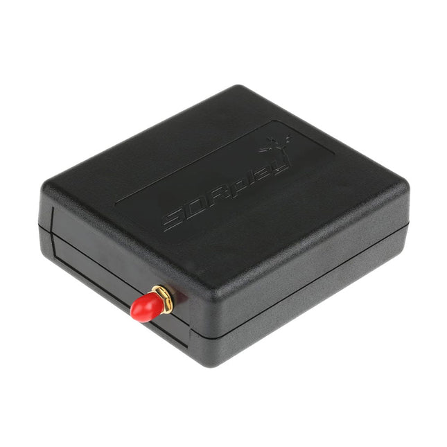
SDRplay SDRplay RSP1B 14-bit SDR Receiver (1 kHz to 2 GHz)
The SDRplay RSP1B is an enhanced version of the popular RSP1A – a powerful, wideband, full-featured 14-bit SDR that covers the RF spectrum from 1 kHz to 2 GHz. The RSP1B comes in a rugged, black-painted steel case and offers significantly improved noise performance. All it needs is a computer and an antenna to deliver excellent communications-receiver functionality. It includes a choice of SDRuno for Windows and the multi-platform SDRconnect software for Windows, macOS, and Linux (supplied free of charge by SDRplay). You can monitor up to 10 MHz of spectrum at a time. A documented API allows developers to create new demodulators or applications for the platform. Features Covers all frequencies from 1 kHz through VLF, LF, MW, HF, VHF, UHF and L-band to 2 GHz, with no gaps Receive, monitor and record up to 10 MHz of spectrum at a time Free use of windows-based SDRuno software which provides an ever-increasing feature-set Strong and growing software support network Calibrated S meter/ RF power and SNR measurement with SDRuno (including datalogging to .CSV file capability) Documented API provided to allow demodulator or application development on multiple platforms Excellent dynamic range for challenging reception conditions Works with popular 3rd party SDR software (including HDSDR, SDR Console and Cubic SDR) ExtIO based plugin available Software upgradeable for future standards Strong and growing software support network API provided to allow demodulator or application development Multiplatform driver and API support including Windows, Linux, Mac, Android and Raspberry Pi Up to 16 individual receivers in any 10 MHz slice of spectrum using SDRuno Calibrated S meter and power measurements with SDRuno Stand-alone windows-based spectrum analyser software available (with sweep, sample and hold features) Ideal for monitoring of ISM/ IoT/ Telemetry bands <2 GHz Ideal for portable operation Specifications Frequency Range 1 kHz – 2 GHz Antenna Connector SMA Antenna Impedance 50 Ohms Current Consumption (Typical) 185 mA (excl. Bias-T) USB Connector USB Type B Maximum Input Power +0 dBm Continuous+10 dBm Short Duration ADC Sample Rates 2-10.66 MSPS ADC Number of Bits 14 bit 2-6.048 MSPS12 bit 6.048-8.064 MSPS10 bit 8.064-9.216 MSPS8 bit >9.216 MSPS Bias-T 4.7 V100 mA guaranteed Reference 0.5ppm 24 MHz TCXO.Frequency error trimmable to 0.01ppm in field. Operating Temperature Range -10˚C to +60˚C Dimensions 98 x 88 x 34 mm Weight 110 g Downloads Datasheet Software RSP1B vs RSPdx vs RSPduo RSP1B RSPdx RSPduo Continuous coverage from 1 kHz to 2 GHz ✓ ✓ ✓ Up to 10 Mhz visible bandwidth ✓ ✓ ✓ 14-bit ADC silicon technology plus multiple high-performance input filters ✓ ✓ ✓ Software selectable AM/FM & DAB broadcast band notch filters ✓ ✓ ✓ 4.7 V Bias-T for powering external remote antenna amplifier ✓ ✓ ✓ Powers over the USB cable with a simple type B socket ✓ ✓ ✓ 50Ω SMA antenna input(s) for 1 kHz to 2 GHz operation (software selectable) 1 2 2 Additional software selectable Hi-Z input for up to 30 Mhz operation ✓ Additional software selectable 50Ω BNC input for up to 200 MHz operation ✓ Additional LF/VLF filter for below 500 kHz ✓ 24 MHz reference clock input (+ output on RSPduo) ✓ ✓ Dual tuners enabling reception on 2 totally independent 2 MHz ranges ✓ Dual tuners enabling diversity reception using SDRuno ✓ Robust and strong plastic case (with internal RF shielding layer) ✓ Rugged black painted steel case ✓ ✓ Overall performance below 2 MHz for MW and LF + ++ + Multiple simultaneous applications + + ++ Performance in challenging fading conditions (*using diversity tuning) + + *++
€ 148,99
-
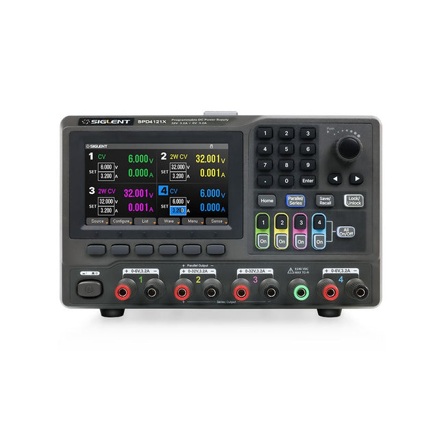
Siglent Siglent SPD4121X 4-ch DC Power Supply (285 W)
The Siglent SPD4121X is a 4-channel DC Linear Programmable Power Supply equipped with a 4.3-inch TFT-LCD display, friendly human-machine interface, and excellent performance indicators. Real-time waveform display provides engineers with an informative user interface. SPD4121X offers a total output power of 285 W with a resolution of 1 mV/1 mA. The maximum voltage and current for each channel are as follows: CH1: 15 V/1.5 A CH2: 12 V/10 A CH3: 12 V/10 A CH4: 15 V/1.5 A Features Rated output power: 285 W Rated voltage: 32 V, 12 V, 30 V Up to four high-precision power supplies with independent controllable outputs, supporting CH2 and CH3 series and parallel connections Clear graphical interface with waveform and timer display modes 5-digit voltage and current display with minimum resolution of 1 mV, 1 mA Fast output response time: <50us The high current channel support remote voltage compensation sense function. The maximum compensation voltage is 0.6 V Overvoltage protection and overcurrent protection or safe and accurate operation Equipped with a 4.3-inch TFT-LCD display (480 x 272 resolution) USB and LAN standard communication USB-GPIB module is optional Excellent channel density with up to 4 channels in a 3U half rack package Internal data storage for setups and parameters Embedded Web Server with instrument communication that doesn’t require software installation Fully SCPI programming command set support as well as a LabView driver for remote control and system automation Specifications SPD4323X SPD4121X SPD4306X Channel Output CH1: Voltage 0 to 6 V Current 0 to 3.2 ACH2: Voltage 0 to 32 V Current 0 to 3.2 ACH3: Voltage 0 to 32 V Current 0 to 3.2 ACH4: Voltage 0 to 6 V Current 0 to 3.2 A CH1: Voltage 0 to 15 V Current 0 to 1.5 ACH2: Voltage 0 to 12 V Current 0 to 10 ACH3: Voltage 0 to 12 V Current 0 to 10 ACH4: Voltage 0 to 15 V Current 0 to 1.5 A CH1: Voltage 0 to 15 V Current 0 to 1.5 ACH2: Voltage 0 to 30 V Current 0 to 6 ACH3: Voltage 0 to 30 V Current 0 to 6 ACH4: Voltage 0 to 15 V Current 0 to 1 A Resolution 1 mV, 1 mA 1 mV, 1 mA 1 mV, 1 mA Setting Accuracy Voltage: ±(0.03% of reading+10) mV, Current: ±(0.3% of reading+10) mA Voltage: ±(0.03% of reading+10) mV, Current: ±(0.3% of reading+10) mA Voltage: ±(0.03% of reading+10) mV, Current: ±(0.3% of reading+10) mA Readback Accuracy Voltage: ±(0.03% of reading+10) mV, Current: ±(0.3% of reading+10) mA Voltage: ±(0.03% of reading+10) mV, Current: ±(0.3% of reading+10) mA Voltage: ±(0.03% of reading+10) mV, Current: ±(0.3% of reading+10) mA Display 4.3" TFT-LCD 5-digit voltage and current display 4.3" TFT-LCD 5-digit voltage and current display 4.3" TFT-LCD 5-digit voltage and current display Output power 240 W 285 W 400 W Included 1x Siglent SPD4121X Power Supply 1x Power cord (EU) 1x Output test cord (3 A) 1x USB cable 1x Quick start guide Downloads Datasheet Manual Quick start
€ 871,20
-
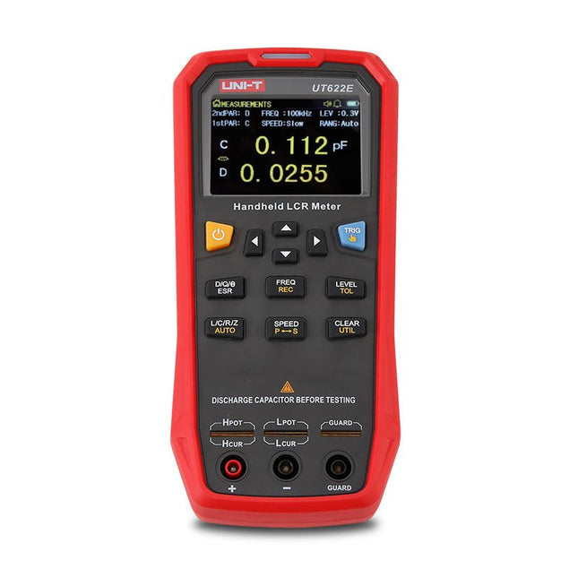
Uni-Trend UNI-T UT622E LCR Meter
The UT622E handheld LCR meter features powerful functions, high accuracy, fast speed, and long standby time. With a clear and intuitive 2.8-inch TFT LCD display, large-capacity rechargeable battery, and 100 kHz test frequency, the meter can be used for longstanding accurate and convenient measurement in any occasion. It is suitable for the measurement and screening of inductance, capacitance, and resistance in laboratories, production lines, maintenance points, etc. Features Max. test frequency: 100 kHz Accuracy: 0.1% Display count: 99999 Max. test rate: 20 times/s DCR: Yes Connectivity: Mini-USB Display: 2.8" TFT LCD Specifications Testfrequency 100 Hz, 120 Hz, 1 kHz, 10 kHz, 100 kHz Test level 0.1 Vmrs, 0.3 Vrms, 1 Vrms Output impedance 100 Ω Measurement parameters Primary: L/C/R/Z/DCRSecondary: D/Q/Θ/ESR DSR speed test Fast (20 times/s), medium (5 times/s), or slow (2 times/s) Range Auto/Hold Tolerance range 1%~20% Equivalent mode Series/Parallel Clearing connection Open/Short circuit Fuse of test ports 0.1 A/250 V Communication interface Mini-USB MAX reading of primary parameters 99999 MIN resolution 0.0001 Maximum accuracy 0.10% L 0.00 µH~99.999 H C 0.00 pF~99.999 mF Z/R 0.0000 Ω~9.9999 MΩ ESR 0.0000 Ω~999.99 Ω D 0.0000~9.9999 Q 0.0000~99999 Θ -179.9°~179.9° DCR 0.01 mΩ~20.000 MΩ Power supply 3.7 V/1800 mAh lithium polymer battery Display 2.8" TFT LCD (320x240) Dimensions 93 x 192 x 44 mm Weight 420 g Included UT622E LCR meter Short circuit board Four-terminal kelvin test leads USB cable Manual Downloads Datasheet Manual Software
€ 325,49
-

Siglent Siglent SDM3045X True RMS Multimeter
The Siglent SDM3045X is a 4½ digit digital (66000 counts, sampling rate 150 Sa/s) multimeter incorporating a dual-display and is especially well suited for the needs of high-precision, multifunction and automatic measurement. With its large 4.3" (10.9 cm) TFT color display (480x272 pixels), the menu navigation is very intuitive to use and very easy to read. Features Real 4½ digit (66000 counts) readings resolution Up to 150 rdgs/s measurement speed True-RMS AC Voltage and AC Current measuring 1 GB NAND flash size, mass storage configuration files and data files Built-in cold terminal compensation for thermocouple With easy, convenient and flexible PC software: EasyDMM Standard interface: USB Device, USB Host, LAN USB & LAN remote interfaces support common SCPI command set. Compatible with other popular DMMs on the market. Application Fields Research Laboratory Development Laboratory Detection and Maintenance Calibration Laboratory Automatic Production Test Measurement Functions DC Voltage: 600 mV – 1000 V DC Current: 600 μA – 10 A AC Voltage: True-RMS, 600 mV – 750 V AC Current: True-RMS, 60 mA – 10 A 2/4-Wire Resistance: 600 Ω – 100 MΩ Capacitance: 2 nF – 10000 μF Continuity Test: Range is fixed at 2 kΩ Diode Test: Adjustable range is 0-4 V Frequency Measurement: 20 Hz – 500 KHz Period Measurement: 2 μs – 0.05 s Temperature: Support for TC and RTD sensor Max, Min, Average, Standard Deviation, dBm/dB, Relative Measurement, Pass/Fail, Histogram, Trend Chart Specifications DC voltage 200 mV, 2 V, 20 V, 200 V, 1000 V DC current 200 μA, 2 mA, 20 mA, 200 mA, 2 A, 10 A AC voltage True-RMS, 200 mV, 2 V, 20 V, 200 V, 750 V AC current True-RMS, 20 mA, 200 mA, 2 A, 10 A 2/4-wire resistance 200 Ω, 2 K, 20 K, 200 K, 2 M, 10 M, 100 MΩ Capacitance 2 nF, 20 nF, 200 nF, 2 μF, 20 μF, 200 μF, 10000 μF Connectivity Test Range fixed 2 KΩ Diode test Range fixed 2 V Frequency 20 Hz ~ 1 MHz Period 1 μs ~ 0.05 s Temperature Support thermocouple, RTD temperature sensor Maximum input voltage 1000 V Configuration Interface USB Device, USB Host, LAN Included 1x Siglent SDM3065X Multimeter 2x Multimeter Probes 1x Power Cord 1x USB Cable 1x Quick Start Guide Downloads User Manual Datasheet Remote Manual Service Manual
€ 435,33
-

OWON OWON VDS1022I 2-ch USB Oscilloscope (25 MHz)
OWON VDS1022I 2-channel USB oscilloscope (25 MHz) is a oscilloscope for use with a computer. It is powered by USB and has a small size, making it easy to take it with you. The oscilloscope is very economical. It has a shielded USB connection, reducing interference and protecting the computer against over-voltage. The multi port on the scope can be used for external triggering, trigger out or Pass / Fail output. Features 25 MHz bandwidth, and max 1 GS/s real-time sample rate 10M record length Friendly UI: FFT, or X-Y, and waveform 2 views displayed on the same screen Multi-trigger option: edge, video, slope, pulse, and alternate USB isolation – less signal inference, more PC protection USB bus powering, and LAN remote control (optional) Ultra-thin body design, easy portability Specifications Bandwidth 25 MHz Channel 2+1 (multi) Sample Rate 100 MSa/s Horizontal Scale (s/div) 5 ns/div~100s/div, step by 1~2~5 Record Length 5K Max Input Voltage 400 V (PK - PK) (DC+AC, PK - PK) 40 V (PK - PK) (DC+AC, PK - PK) Vertical Resolution (A/D) 8 bits (2 channels simultaneously) Model VDS1022I Vertical Sensitivity 5 mV/div~5 V/div Trigger Type Edge, Pulse, Video, Slope, and Alternate Trigger Mode Auto, Normal, and Single Acquisition Mode Sample, Peak Detect, and Average Waveform Math +, -, ×, ÷, invert, FFT Communication Interface USB 2.0 (isolation) Multi-function Interface Signal Type Level Standard TTL Power Supply 5.0 V/1 A Power Consumption ≤2.5 W Dimensions (W × H × D) 170 x 120 x 18 mm Weight 0.26 kg Included 1x OWON VDS1022I oscilloscope 1x CD-ROM 1x Quick start guide 2x Oscilloscope probe 1x Probe tool 1x Power adapter 1x USB cable 1x Silicone case protectors 1x Power cable Downloads Datasheet User manual SCPI protocol USB driver
€ 119,00
-
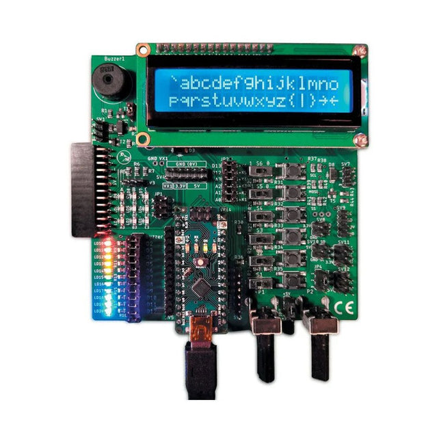
Elektor Labs Elektor Arduino Nano MCCAB Training Board
The Elektor Arduino Nano MCCAB Training Board contains all the components (incl. Arduino Nano) required for the exercises in the "Microcontrollers Hands-on Course for Arduino Starters", such as light-emitting diodes, switches, pushbuttons, acoustic signal transmitters, etc. External sensors, motors or assemblies can also be queried or controlled with this microcontroller training system. Specifications (Arduino Nano MCCAB Training Board) Power Supply Via the USB connection of the connected PC or an external power supply unit (not included) Operating Voltage +5 Vcc Input Voltage All inputs 0 V to +5 V VX1 and VX2 +8 V to +12 V (only when using an external power supply) Hardware periphery LCD 2x16 characters Potentiometer P1 & P2 JP3: selection of operating voltage of P1 & P2 Distributor SV4: Distributor for the operating voltagesSV5, SV6: Distributor for the inputs/outputs of the microcontroller Switches and buttons RESET button on the Arduino Nano module 6x pushbutton switches K1 ... K6 6x slide switches S1 ... S6 JP2: Connection of the switches with the inputs of the microcontroller Buzzer Piezo buzzer Buzzer1 with jumper on JP6 Indicator lights 11 x LED: Status indicator for the inputs/outputs LED L on the Arduino Nano module, connected to GPIO D13 JP6: Connection of LEDs LD10 ... LD20 with GPIOs D2 ... D12 Serial interfacesSPI & I²C JP4: Selection of the signal at pin X of the SPI connector SV12 SV9 to SV12: SPI interface (3.3 V/5 V) or I²C interface Switching output for external devices SV1, SV7: Switching output (maximum +24 V/160 mA, externally supplied) SV2: 2x13 pins for connection of external modules 3x3 LED matrix(9 red LEDs) SV3: Columns of the 3x3 LED matrix (outputs D6 ... D8) JP1: Connection of the rows with the GPIOs D3 ... D5 Software Library MCCABLib Control of hardware components (switches, buttons, LEDs, 3x3 LED matrix, buzzer) on the MCCAB Training Board Operating Temperature Up to +40 °C Dimensions 100 x 100 x 20 mm Specifications (Arduino Nano) Microcontroller ATmega328P Architecture AVR Operating Voltage 5 V Flash Memory 32 KB, of which 2 KB used by bootloader SRAM 2 KB Clock Speed 16 MHz Analog IN Pins 8 EEPROM 1 KB DC Current per I/O Pins 40 mA on one I/O pin, total maximum 200 mA on all pins together Input Voltage 7-12 V Digital I/O Pins 22 (6 of which are PWM) PWM Output 6 Power Consumption 19 mA Dimensions 18 x 45 mm Weight 7 g Included 1x Elektor Arduino Nano Training Board MCCAB 1x Arduino Nano
€ 69,95
Best Price
-
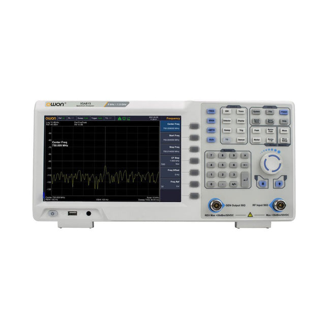
OWON OWON XSA815-TG Spectrum Analyzer (9 kHz – 1.5 GHz)
The OWON XSA815-TG (9 kHz-1.5 GHz) is a cost effective spectrum analyzer with tracking generator included and a frequency resolutions of 1 Hz. Features Frequency Range from 9 kHz to 1.500009 GHz 9-inch display 9 kHz to 1 MHz -95 dBm Displayed Average Noise Level, 1 MHz to 500 MHz 140 dBm (Typical), <-130 dBm Phase Noise -10 kHz <-80 dBc/Hz 100 kHz <-100 dBc/Hz 1 MHz <-115 dBc/Hz Resolution Bandwidth (-3 dB): 1 Hz to 1 MHz, in 1-3-5-10 sequence Tracking Generator Kit: 100 kHz to 1.500009 GHz Specifications Frequency Range 9 kHz to 500.009 MHz Frequency Resolution 1 Hz Frequency Span 9 kHz to 1.500009 GHz Span Range 0 Hz, 100 Hz to max frequency of instrument Span Uncertainty ±span / (sweep points-1) SSB Phase Noise (20°C to 30°C, fc=1 GHz) Carrier Offset 10 kHz <-80 dBc/Hz | 100 kHz <-100 dBc/Hz | 1 MHz <-115 dBc/Hz Resolution Bandwidth (-3 dB) 1 Hz to 1 MHz, in 1-3-5-10 sequence RBW Accuracy <5% typical Resolution Filter Shape Factor (60 dB: 3 dB) <5 typical Video Bandwidth (-3 dB) 10 Hz to 1 MHz, in 1-3-5-10 sequence Amplitude measurement range DANL to +10 dBm, 100 kHz to 10 MHz, Preamp Off DANL to +20 dBm, 10 MHz to 1.5 GHz, Preamp Off Reference Level -80 dBm to +30 dBm, 0.01dB by step Preamp 20 dB, nominal, 100 kHz to 1.5 GHz Input Attenuator 0 to 40 dB, 1 dB by step Display Average Noise Level Input attenuation = 0 dB, RBW = VBW = 100 Hz, sample detector, trace average ≥ 50, 20°C to 30°C, input impedance = 50 Ω) Preamp Off 9 kHz to 1 MHz -95 dBm (Typical), <-88 dBm Preamp Off 1 MHz to 500 MHz -140 dBm (Typical), <-130 dBm Preamp On 100 kHz to 1 MHz -135 dBm (Typical), <-128 dBm Preamp On 1 MHz to 500 MHz -160 dBm (Typical),<-150 dBm Tracking Generator (optional) Frequency Range 100 kHz to 1.500009 GHz Output power level range -40 dBm to 0 dBm Output level resolution 1 dB Output flatness Relative to 50 MHz | ±3 dB Tracking generator spurious Harmonic spurious -30 dBc (Tracking generator output power -10 dBm) Non-harmonic spurious -40 dBc (Tracking generator output power -10 dBm) Tracking generator to input terminal isolation -60 dB (Tracking generator output power 0 dBm) Tracking generator to input terminal isolation -60 dB (Tracking generator output power 0 dBm) Tracking generator to input terminal isolation -60 dB (Tracking generator output power 0 dBm) Dimensions 375 x 185 x 120 mm Weight 3.7 kg Included 1x XSA815-TG 1x 220 V AC power cord 1x USB Cable 1x Quickstart guide Downloads Quick Guide Specifications
€ 907,50
-

Elektor Publishing Logic Analyzer im Einsatz
USB-Logikanalysatoren am PC mit Arduino, Raspberry Pi und Co Schritt-für-Schritt-Anleitungen führen Sie in die Analyse moderner Protokolle von I²C, SPI, UART, RS-232, NeoPixel, WS28xx, HD44780 und 1-Wire ein. Anhand von zahlreichen Experimentierschaltungen mit dem Raspberry Pi Pico, Arduino Uno und dem Bus Pirate üben Sie die praxisnahe Anwendung gängiger USB-Logikanalysatoren ein. Alle in diesem Buch vorgestellten Experimentierschaltungen wurden vollständig getestet und sind funktionsfähig. Die notwendigen Programmlistings sind enthalten, es sind keine besonderen Programmier- oder Elektronikkenntnisse für diese Schaltungen notwendig. Es werden die Programmiersprachen MicroPython und C mit den Entwicklungsumgebungen Thonny und Arduino IDE eingesetzt. Dieses Buch verwendet mehrere Modelle flexibler und weit verbreiteter USB-Logikanalysatoren und zeigt die Stärken und Schwächen jeder Preisklasse. Sie werden kennenlernen, welche Kriterien für Ihre Arbeit wichtig sind und in der Lage sein, das für Sie passende Gerät zu finden. Egal ob Arduino, Raspberry Pi oder Raspberry Pi Pico: Die abgebildeten Beispielschaltungen ermöglichen einen schnellen Start in die Protokollanalyse und können auch als Grundlage für eigene weitere Experimente dienen. Sie werden alle wichtigen Begriffe und Zusammenhänge kennenlernen, eigene Experimente durchführen, selbstständig Protokolle analysieren und nach der Lektüre dieses Buches – im Bereich der digitalen Signale und Protokolle – ein umfassendes Wissen aufgebaut haben.
€ 39,80
Best Price


