
Search results for "fnirsi OR soldering OR iron OR stand"
-

FNIRSI FNIRSI SG-003A Signal Generator
The FNIRSI SG-003A multi-functional Signal Generator a.k.a. Process Meter/Calibrator is a high-precision voltage/current generator and meter. The SG-003A provides highly accurate reference voltages or currents for testing and calibrating other measurement instruments like multimeters and oscilloscopes. Besides voltages and currents, the SG-003A also generates rectangular pulse signals with precisely programmable frequencies and duty cycles. Its converter mode turns the SG-003A into a precision voltage-controlled current source, or current-controlled voltage source, and even a voltage- or current-controlled frequency generator. The SG-003A is a great tool for checking your multimeter’s accuracy and precision, and for testing e.g. LEDs. Features Accuracy (voltage/current) 0.1% ±0.005 Resolution (current) 0.01 mA Frequency 0-10 kHz Resolution 5 digits Output power 24 V Display 2.4" TFT LCD (320 x 240) Dimensions 92 x 72 x 30 mm Weight 165 g Specifications Signal Range Precision Resolution Max load External power supply Active current output 0~24 mA ±(0.1% + 0.005) 0.01 mA 750 Ω Passive current output (XMT) 0~24 mA ±(0.1% + 0.005) 0.01 mA 0~30 V Voltage output 0~24 V ±(0.1% + 0.005) 0.01 V 24 V loop 0~24 mA ±(0.1% + 0.005) 0.01 mA Frequency output 0~9999 Hz ±2% 5 digits Current input 0~24 mA ±(0.1% + 0.005) 0.01 mA Voltage input 0~30 V ±(0.1% + 0.005) 0.01 V Included 1x FNIRSI SG-003A Signal generator 4x Test clips 1x USB charger 1x USB-C cable 1x Manual Downloads Manual Firmware V4.3
€ 69,95
-

Elecrow Elecrow AI Starter Kit for Jetson Orin Nano
All-in-One AI Learning and Development Platform for Edge Intelligence This NVIDIA Jetson-based AI Starter Kit is a versatile platform for learning, development, and hands-on experimentation in Edge AI. Designed for use with the NVIDIA Jetson Orin Nano, the kit combines an 11.6-inch IPS display, an 8-megapixel pan-tilt camera, and an AI voice interaction system. It includes 30 functional modules and 38 carefully designed Python courses that progress from beginner to advanced level. The course content covers Python fundamentals, sensor technology, AI vision, and image recognition. With step-by-step practical exercises ranging from basic programming to real-world computer vision applications, this kit provides an ideal platform for students, makers, developers, and anyone looking to explore artificial intelligence and edge computing. Please note: The NVIDIA Jetson Orin Nano is not included. Features Designed for the NVIDIA Jetson Orin Nano AI voice interaction module 8 MP camera with pan-tilt control Supports object and face tracking No soldering or complex wiring required Built-in 11.6-inch IPS display 30 functional modules 38 step-by-step Python lessons I²C, UART, and GPIO expansion interfaces Portable carrying case included Specifications Main Processor Jetson Orin Nano Number of Sensors 30 Sensor Board Design Integrated sensor board, no soldering or complex wiring required Screen 11.6-inch IPS Screen Screen Resolution 1366 x 768 Camera IMX219 8MP Expansion Interfaces 2x I²C, 1x UART, 1x IO D13, 1xIO D12 Programming Environment Based on Python Number of Tutorials 38 creative tutorials Target Audience Students, teachers, hardware enthusiasts Application Scenarios Ideal for learning AI programming, Jetson Orin Nano basics Dimensions 300 x 200 x 100 mm Module List Module Quantity Temperature & Humidity Sensor 1 pcs Button 4 pcs Ultrasonic Ranging Sensor 1 pcs Light Sensor 1 pcs Linear Potentiometer 1 pcs Buzzer 1 pcs LCD 1 pcs Infrared Remote 1 pcs Relay 1 pcs NFC 1 pcs PIR Motion Sensor 1 pcs Joystick 1 pcs 4-Digital Display 1 pcs LED 1 pcs Microphone 1 pcs Speaker 1 pair Vibration Motor 1 pcs Touch Sensor 1 pcs 8x8 RGB Matrix 1 pcs Atmospheric pressure sensor 1 pcs Tilt Switch 1 pcs Stepper Motor 1 pcs Accelerometer & Gyro 1 pcs Gas Sensor (MQ2) 1 pcs Hall Sensor 1 pcs Rotary Encoder 1 pcs U-shaped photoelectric switch 1 pcs NTC 1 pcs Servo 2 pcs Monocular camera 1 pcs Included 1x Elecrow AI Starter Kit for Jetson Orin Nano 1x IR Remote Control 1x NFC Card 1x 128 GB SD Card 1x 40-pin GPIO Cable 2x 22-pin FPC Cable 2x 24-pin FPC Cable 1x Jetson DP & USB Adapter Board Not included NVIDIA Jetson Orin Nano Downloads Manual Wiki OpenClaw Install and Config Guide
€ 249,00
Members: € 224,10
-

Quick Quick 861DW Hot Air Rework Station (1000 W)
The Quick 861DW is an advanced Hot Air Rework Station with a 1000 W heating power. It is designed for professional soldering electronic SMD components using lead-free solders. Features Three programmable channels CH1, CH2 and CH3 (for air volume and temperature parameters). Password protection and button lock function available. Magnetic switch in a stand can automatically puts the station into sleep mode when not in use. Easy real-time operation, auto sleeping function available, parameters can be set in sleeping mode. Closed loop sensor, temperature controlled by micro-computer zero trigger, large power, rapid temperature rising, temperature can be easily and accurately adjusted, not affected by airflow. Brushless vortex fan, wide range of airflow adjustable, suitable for many applications. Auto cooling function available, long lifetime ceramic heater. Specifications Power 1000 W Operating voltage AC 200~240 V Temperature range 100-500°C Air volume 1-120 class Air flow 50 l/min (Max) Dimensions 188 x 245 x 135 mm Weight 3.65 kg Downloads Manual
€ 255,73
-

Elektor Publishing Professional SMD Assembly
Practical Low-Cost Methods for Reliable PCB Production This book explains how to carry out reliable SMD assembly using affordable tools and small-scale equipment. It follows the complete workflow step by step, including tool selection, solder paste handling, stencil use, component placement, reflow methods, inspection, and rework. The focus is on bench-level and small-lab production rather than industrial assembly lines. It shows practical methods for building single and double-sided SMD boards with repeatable results. Topics include solder paste and flux, temperature profiles, hot air and hotplate techniques, small reflow ovens, inspection methods, and defect correction. Checklists and example workflows are included to help reduce errors and improve consistency. Key features: Tools and supplies for SMD assembly and rework Solder paste types, storage, and handling Stencils and paste application methods Pick and place workflow and component orientation Temperature profiles and reflow methods Hot air, hotplate, and reflow oven processes Inspection and quality control Common defects such as tombstoning and solder bridges Practical rework and component replacement Bench-level professional workflows and checklists This book is designed as a practical bench reference for anyone who wants to assemble and troubleshoot their own SMD boards with reliable results.
€ 24,95
Members: € 22,46
-
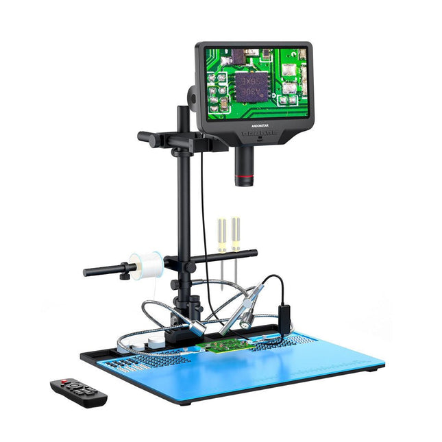
Andonstar Andonstar AD409 Max-ES 10.1" HDMI Digital Microscope (incl. Endoscope)
The Andonstar AD409 Max-ES boosts a high-quality metal lens and a unique UV filter design. Crafted from top-tier industrial-grade materials, it delivers unmatched precision and durability, ensuring a reliable product experience. The UV filter positioned in front of the metal lens blocks soldering heat, smoke, and dust, safeguarding the lens and making it perfect for soldering and maintenance professionals. The AD409 Max-ES features an oversized Max station (46 x 37 x 47.5 cm) and an advanced tool set, expanding the soldering station area by 370%. This upgrade meets the demands of professional soldering tasks and provides ample workspace for larger projects. The easy-to-use tool holder keeps tools within reach, ensuring they are always accessible. Additionally, the soldering helping hands with rotatable clamps simplify soldering and repair tasks, enhancing efficiency and convenience. The endoscope offers an all-around 360° view. This allows for clear observation of components from all sides and inside pipes, eliminating blind spots and ensuring thorough inspections. Features High-quality Metal Lens and Unique UV Filter Design New Max station Easy-to-use Tool Holder and Soldering Helping Hands Microscope with Endoscope All-around View 360° Professional HDMI Digital Microscope supports Multiple Output Methods 8 Levels adjustable LEDs Convenient Wireless Remote Control Specifications Screen size 10.1 inch (1280x800) Image sensor 4 MP Video output UHD 2880x2160 (24fps)FHD 1920x1080 (60fps/30fps)HD 1280x720 (120fps) Video format MP4 Magnification Up to 300 times (27 inch HDMI monitor) Photo resolution Max. 24 MP (5600x4200) Photo format JPG Focus range Min. 5 cm Frame Rate Max. 120fps Video interface HDMI Storage microSD card (up to 64 GB) PC support Windows, PC software with measurement Mobile phone, tablet terminal support Support WiFi connection and measurement Power source 5 V DC Light source 2 LEDs with the stand Endoscope Yes Stand size 46 x 37 x 47.5 cm (18.1 x 14.6 x 18.7") Included 1x Andonstar AD409 Max-ES Digital Microscope 1x Endoscope 1x Stand with 2 LEDs 1x UV filter (already assembled in the lens) 1x Soldering mat 1x Beam 1x Column 1x Tool holder 1x Soldering Helping Hands 1x Power adapter 1x Power cable 1x HDMI cable 1x USB cable 1x IR remote 1x Manual Downloads Manual Software
€ 399,00€ 339,00Best Price
-

Elektor Digital Professional SMD Assembly (E-book)
Practical Low-Cost Methods for Reliable PCB Production This book explains how to carry out reliable SMD assembly using affordable tools and small-scale equipment. It follows the complete workflow step by step, including tool selection, solder paste handling, stencil use, component placement, reflow methods, inspection, and rework. The focus is on bench-level and small-lab production rather than industrial assembly lines. It shows practical methods for building single and double-sided SMD boards with repeatable results. Topics include solder paste and flux, temperature profiles, hot air and hotplate techniques, small reflow ovens, inspection methods, and defect correction. Checklists and example workflows are included to help reduce errors and improve consistency. Key features: Tools and supplies for SMD assembly and rework Solder paste types, storage, and handling Stencils and paste application methods Pick and place workflow and component orientation Temperature profiles and reflow methods Hot air, hotplate, and reflow oven processes Inspection and quality control Common defects such as tombstoning and solder bridges Practical rework and component replacement Bench-level professional workflows and checklists This book is designed as a practical bench reference for anyone who wants to assemble and troubleshoot their own SMD boards with reliable results.
€ 19,95
Members: € 17,96
-

Elektor Labs Elektor Sand Clock for Raspberry Pi Pico (incl. Laser Head Upgrade)
This bundle contains the popular Elektor Sand Clock for Raspberry Pi Pico and the new Elektor Laser Head Upgrade, offering even more options for displaying the time. Not only can you "engrave" the current time in sand, you can now alternatively write it on a glow-in-the-dark foil or create green drawings. Contents of the bundle Elektor Sand Clock for Raspberry Pi Pico (normal price: €50) Elektor Laser Head Upgrade for Sand Clock (normal price: €35) Elektor Sand Clock for Raspberry Pi (Raspberry Pi-based Eye Catcher) A standard sand clock just shows how time passes. In contrast, this Raspberry Pi Pico-controlled sand clock shows the exact time by "engraving" the four digits for hour and minute into the layer of sand. After an adjustable time the sand is flattened out by two vibration motors and everything begins all over again. At the heart of the sand clock are two servo motors driving a writing pen through a pantograph mechanism. A third servo motor lifts the pen up and down. The sand container is equipped with two vibration motors to flatten the sand. The electronic part of the sand clock consists of a Raspberry Pi Pico and an RTC/driver board with a real-time clock, plus driver circuits for the servo motors. A detailed construction manual is available for downloading. Features Dimensions: 135 x 110 x 80 mm Build time: approx. 1.5 to 2 hours Included 3x Precut acrylic sheets with all mechanical parts 3x Mini servo motors 2x Vibration motors 1x Raspberry Pi Pico 1x RTC/driver board with assembled parts Nuts, bolts, spacers, and wires for the assembly Fine-grained white sand Elektor Laser Head Upgrade for Sand Clock The new Elektor Laser Head transforms the Sand Clock into a clock that writes the time on glow-in-the-dark film instead of sand. In addition to displaying the time, it can also be used to create ephemeral drawings. The 5 mW laser pointer, with a wavelength of 405 nm, produces bright green drawings on the glow-in-the-dark film. For best results, use the kit in a dimly lit room. Warning: Never look directly into the laser beam! The kit includes all the necessary components, but soldering three wires is required. Note: This kit is also compatible with the original Arduino-based Sand Clock from 2017. For more details, see Elektor Magazine 1-2/2017 and Elektor Magazine 1-2/2018.
€ 84,95€ 69,95Best Price
-

Elektor Labs Elektor Low-Noise Lab Power Supply
The Elektor Low-Noise Lab Power Supply is a fully analogue, adjustable, medium-power symmetrical bench supply that contains no switching or digital components. It provides an output voltage adjustable between 0 V and ±22 V, and an output current adjustable from 0 A to 1 A. Because it avoids any form of switching circuitry, the design delivers extremely low noise. To display both output voltages and currents, four miniature moving-coil panel meters are used. Most modern laboratory power supplies and AC adapters employ switch-mode techniques. Even the best examples inevitably exhibit high-frequency ripple and other switching artefacts on their output, which can interfere with the testing of sensitive analogue circuits and disturb low-level measurements. To overcome this, the concept here is a completely analogue power supply. Although less efficient than its switch-mode counterparts, the reduced efficiency is of little importance for test-bench use and ensures cleaner, more reliable measurement results. Because many analogue circuits require a symmetrical supply, this design delivers positive and negative output voltages of equal magnitude. A small amount of adjustment is available to compensate for any imbalance. Naturally, a variable current-limit function is also included. The kit includes the components required to build the power supply, except for the transformers. Specifications Output Voltage 0…+22 V, 0, −22 V Output Current 0…+1 A, 0…−1 A Noise −85 dBV, (at 0.95 A/20 V, B = 22 kHz) −84 dBV (at 0.95 A/20 V, B > 500 kHz) Ripple 50 µVRMS (at 950 mA/20 V, B = 22 kHz, mainly 100 Hz component) Included 3x PCBs: Regulator (PCB-1), Mains Filter (PCB-2) and Transformer (PCB-3) All the components except the AC transformers 4x moving-coil meters Additional parts for wiring (wires, banana sockets, IEC Power entry module, etc.) Not included The three AC transformers An enclosure Parts List For the Regulator PCB (240386-1) Resistors (250 mW, 1%) R1 = 12 Ω R2, R8, R37, R62 = 1 MΩ R3, R7, R10, R13, R17, R20, R22, R30, R35, R42, R45, R47, R55, R60 = 100 Ω, 600 mW R4, R5 = 4.7 kΩ R6 = 100 kΩ R9, R12, R14, R36, R38, R39, R61, R63, R66, R72, R78, R79 = 10.0 kΩ, 600 mW R11 = 9.76 kΩ, 600 mW R15, R40 = 44.2 kΩ, 600 mW R16, R41, R77 = 1 kΩ R18, R43 = 1.5 kΩ, 1 W, 5% R19, R44 = 470 Ω, 1 W, 5% R21, R46 = 330 Ω, 600 mW R23, R24, R48, R49 = 1.0 Ω, 1 W R25, R50 = 1 kΩ, 1 W, 5% R26, R28, R51, R53 = 1.000 kΩ 0.1%, 15 ppm/C R27, R29, R52, R54 = 10.00 kΩ 0.1%, 15 ppm/C R31, R56 = 1.2 kΩ, 1 W, 5% R32, R57 = 47 kΩ R33, R58 = 270 Ω R34, R59 = 27 kΩ R64, R69 = 12.0 kΩ R65 = 3.0 kΩ, 600 mW R67, R80 = 470 Ω, 600 mW R68, R70 = 6.8 kΩ, 600 mW R71 = 30.0 kΩ,, 600 mW R73, R74, R75, R76 = 10 MΩ P1, P2, P3 = 10 kΩ, 200 mW, 20%, potentiometer, 1 turns, single, lin., panel mount P4, P5 = 500 Ω, 500 mW, 10%, trimmer, 25 turns, 3296Y-1-501LF Bourns P6, P7 = 10 kΩ, 500 mW, 10%, trimmer, 25 turns, 3296Y-1-501LF Bourns Capacitors C1 = 100 nF, 50 V, 10%, ceramic X7R, LS 5 mm C2, C3, C6, C7, C30 = 10 µF, 63V, 20%, LS 2.5 mm, 3000hours@105°C C4, C5, C8, C9, C13, C14, C18, C19, C23, C24, C28, C29, C31, C32, C38, C39 = 100 nF, 250 V, 10%, PET, LS 7.5 mm C10, C20 = 47 nF, 100 V, 5%, PET, LS 5 mm C11, C21 = 10 nF, 100 V, 5%, PET, LS 5 mm C12, C22 = 220 µF, 35 V, 20%, 0.024 Ω, LS2.5/3.5 mm, Ir 3.4 A, 2000hours@125°C, polymer C15, C25 = 120 µF, 50 V, 20%, ESR 0.02 Ω, Diam. 10 mm max., LS 5 mm C16, C26 = 15 nF, 100 V, 5%, PET, LS 5 mm C17, C27 = 47 nF, 100 V, 5%, PET, LS 5 mm C33, C34 = 22 µF, 50 V, 20%, LS 2 mm, 10000 hours @ 105°C C35, C36, C44, C45 = 1 µF, 100 V, 10%, LS 5 mm, ceramic X7R C37 = 100 uF, 50 V, 20%. LS 3.5 mm C40, C41, C42, C43, C46, C47, C48, C49 = 1000 µF, 50 V, 20%, LS 5/7.5 mm, Ir 3.32 A, 10000hours@105°C, D 16 mm C50, C51, C52, C53 = 47 nF, 100 V, 10%, ceramic X7R, LS 5 mm Inductors L1, L2 = 4.7 µH, 3.2 A, 0.033 Ω, LS 5 mm, RLB0914-4R7ML Bourns L3 = Commom mode choke, 14.5 mH, 3 A, SSRH24NH-30145 Kemet Semiconductors D1, D2, D3, D4, D5, D9, D10, D11, D15 = BAT85, DO-34 D6, D7, D12, D13 = SR560, DO-201AD D8, D14, D16 = 1N4148, DO-35 D17 = Zenerdiode, 5.6 V, 0.5 W, DO-41 D18, D19 = 1N4004, DO-41 D20, D21 D22, D23 = V30100CI-M3/P, dual common cathode, TO-220 D24 = Zener diode, 30 V, 1 W, DO-41 LED1, LED2 = LED, red, T-1 (3 mm) LED3, LED4 = LED, green, T-1 (3 mm) TVS1, TVS2 = BZW50-33B, R6 T1, T2, T4 = BC337.25, TO-92 T3 = NJW0302G, TO-3P T5, T6, T8 = BC327.25, TO-92 T7 = NJW0281G, TO-3P T9 = BD139, TO-126 (SOT-32) IC1 = LM334Z, TO-92 IC2 = LM4040AIZ-5.0/NOPB, TO-92 (TO-226AA-3) IC3, IC4 = OPA2992IDR, SOIC-8 IC5, IC6 = OPA4992IDR, SOIC-14 IC7 = OPA992IDBVR, SOT-23-5 IC8 = LM339N, DIP-14 IC9 = LM317, TO-220 IC10 = LM337, TO-220 Others F1, F2 = 5×20 mm fuse, 1.6 A, fast acting HS1, HS2 = Heatsink MC33271 (for T3/T7), 2.7°C/W, PCB mount, height 63.5 mm K1, K4 = 3-way screw terminal block, LS 3.5 mm, max. 1.5 mm² K2, K3 = 3-way screw terminal block, LS 3.5 mm, max. 1 mm² M1, M3 = Moving coil meter, Range 30 V, type 91C4, 45×45 mm M2, M4 = Moving coil meter, Range 1 A, type 91C4, 45×45 mm² RE1 = Relay DPDT,5V, UA2-5NU Miscellaneous 3× 3-way screw terminal block, LS 3.5 mm, max. 1 mm² (for P1, P2, P3) 4× Pin header, 1×2, vertical, pitch 2.54 mm (for LED1, LED2, LED3, LED4) 4× Pin socket, 1×2, vertical. pitch 2.54 mm (for LED1, LED2, LED3, LED4) 2× Heatsink FK222SA220, 20°C/W, PCB mount (for IC9 & IC10) 2× Mica thermal pad for TO-220, 12×18×0.05 mm (for IC9 & IC10) 2× Insulating bushing IB 6, TO-220 (for IC9 & IC10) 2× Ceramic thermal pad, 23×20×2 mm (for T3 & T7) 2× PCB Fuse Holder, for 5×20 mm fuse, 10 A (for F1, F2) 2× Cover for PCB Fuse Holder, transparent (for F1, F2) 2× 2-way screw terminal block, LS 3.5 mm, max. 1 mm² (for M1 & M3) 2× 2-way screw terminal block, LS 3.5 mm, max. 1.5 mm² (for M2 & M4) 8× M3 solder lug, thickness 0.35 mm (for M1…M4) M4 solder lug, thickness 0.35 mm (to connect 4 mm banana connectors) Screened cable, 1 pair, 2×24 AWG/0.22 mm², 1 m (for P1, P2 & P3) IC socket, DIP, 14 contacts (for IC8) M3 washer, plain, steel M3 screw, 16 mm, steel, pan head M3 nut M3 spring washer 50 mm M3 standoff, steel, male-female 12 mm M3 standoff, steel, male-female 10 mm M3 standoff, steel, male-female M3 screw, 8 mm, steel, pan head For the Mains Fiter PCB (240386-2) Resistor R1 = 220 kΩ, 1 W, 500 V, 5% Capacitors C1, C2 = 470 nF, 305 VAC, Class X2, 11 × 27 mm max., LS 15/22.5 mm C3, C4, C5, C6 = 2.2 nF, 300 VAC, Class Y2, 13 × 4 mm, LS 10 mm, PP Inductors L1, L2 = Common-mode choke, 6.8 mH, 1.7 A, TDK B82732R2172B030 Semiconductor MOV1 = TVS varistor, 300 VAC, S14K300 (230 VAC, B72214S0301K101) and SK14K150 (150 VAC, B72214S0151K101) Others K1, K2 = 3-way screw terminal block, LS 7.62 mm F1 = Time-delay fuse, 0.5 A (230 VAC) or 1 A (115 VAC) Miscellaneous 1× Fuse holder, 5×20 mm, 10 A, 500 VAC 1× Transparent fuse cover 4× 10 mm M3 standoff, steel, male–female 4× M3 screw, 8 mm, steel, pan head 4× M3 nut For the Transformer PCB (240386-3) Resistors R1, R2 = 2.7 kΩ, 600 mW, 1% R3 = 10.0 kΩ, 600 mW, 1% Capacitor C1 = 220 µF, 50 V, 20%, Ø10 mm, LS 5 mm, 4000 h @ 105°C Transformers (not included in this kit!) TR1, TR2, TR3 = 2×7 V, 25 VA, PCB-mounted toroid, 70060K Talema Semiconductors D1–D4 = 1N4148, DO-35 D5, D6 = 1N4004, DO-41 D7 = Zener 5.6 V, 1.3 W, DO-41 LED1 = LED, red, T-1 (3 mm) IC1, IC2 = MOC8021M, CTR ≥ 1000%, DIP-6 Others F1, F2, F3 = 160 mA time-delay fuse (230 VAC) or 315 mA time-delay fuse (115 VAC) K1 = 2-way screw terminal block, LS 7.62 mm K2 = 3-way screw terminal block, LS 3.5 mm, max 1.5 mm² K3, K4 = 3-way screw terminal block, LS 3.5 mm, max 1 mm² RE1, RE2 = Relay DPDT, 5 A/250 VAC / 24 VDC Miscellaneaous 1× Pin header 1×2, pitch 2.54 mm + matching socket for LED1 3× Fuse holder 5 × 20 mm, 10 A, 500 VAC + transparent cover 3× M4 screw, 8 mm, pan head + washer for TR1-TR3 8× M3 screw, 8 mm, pan head + nut + washer 8× 10 mm M3 standoff, steel, male–female 2× IC socket, DIP-6 for IC1 & IC2 Additional Parts 1 m red insulated wire, stranded, 1.5 mm² 0.5 m blue insulated wire, stranded, 1.5 mm² 0.5 m black insulated wire, stranded, 1.5 mm², 0.5 m 2 m red insulated wire, stranded, D 0.56 mm (0.25 mm²) 2 m black insulated wire, stranded, D 0.56 mm (0.25 mm²) 0.5 m Multicore Cable, Flexible, 3 Core, 0.75 mm² (24 x 0.2 mm) Red banana socket Black banana socket Blue banana socket Green banana socket IEC Power Entry Module with switch, IEC C14 3 crimp terminals, FASTON, 4.75 x 0.81 mm 3 knobs Links Elektor Labs JumpStarter Page Article (Part 1) Article (Part 2)
€ 299,00€ 249,00Best Price
-
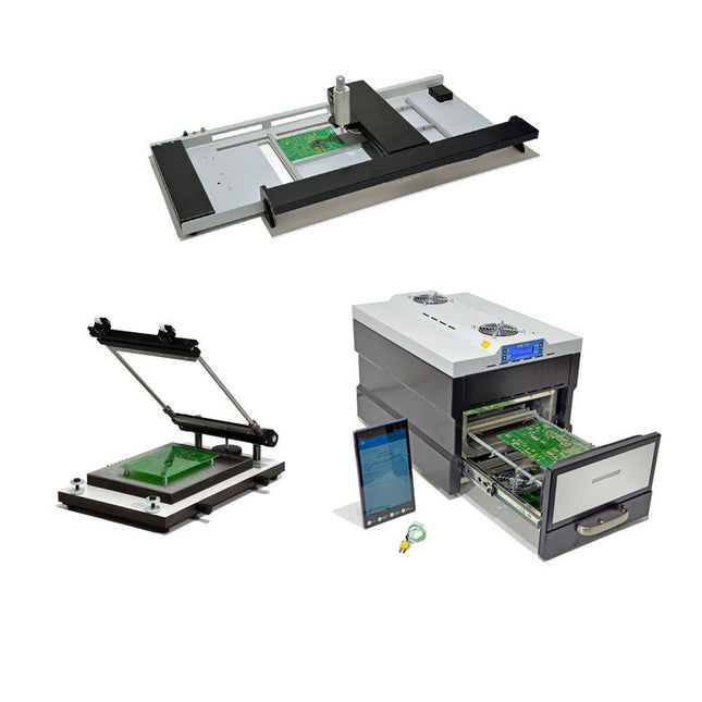
Paggen Werkzeugtechnik SMD Starter I – Production Line for Prototypes
The SMD Starter I prototype production line consists of the stencil printer TSD240, the SMD placement device PlaceMAN and the reflow oven 3LHR10. Stencil printer SD240 (+ Metal Squeegee 155 mm) Stencil size: max. 175 x 255 mm PCB size: max. 180 x 240 mm Size: 410 x 270 x 110 mm Weight: 6.7 kg incl. metal squeegee 155 mm incl. 8 magnets to hold the PCB, 6 of them with M3 grub screw Manual SMD pick-and-place device PlaceMAN for standard components incl. vacuum pump (without feeders, camera, monitor and dispenser) Equipped with smooth-running placement arm, placement head with one-hand operation, rotation of the Z-axis and automatic vacuum switch-off, incl. PCB holder, vacuum unit and 2 placement needles with rubber suction cups. Capacity of feeder (not included) 2x feeder cassette for 10 x 8 mm wheels left 4x feeder cassette for rod feeders for 5 rods each Further feeding systems are possible within the assembly area, e.g. strip-feeder plug-in system Dimensions Base unit (LxWxH): 765 x 390 x 210 mm With feeder cassette for 10 x 8 mm rolls (LxWxH): 765 x 390 x 210 mm With feeder cassette for 10 x 8 mm rolls and feeder cassette for rod feeder (LxWxH): 765 x 430 x 210 mm (height may vary due to rod length) With feeder cassette for 10 x 8 mm rolls incl. holder for 10 rolls and feeder cassette for rod feeder (LxWxH): 765 x 430 x 210 mm (height may vary due to rod length) Specifications Weight of basic unit: approx. 6 kg Axis travel (x,y,z): 470 x 230 x 15 mm Max. working area: 380 x 240 mm Max. PCB size: 230 x 360 mm Power supply: 230/12 V, 800 mA Power supply vacuum pump: 230 V, 6 W 3LHR10 Reflow Oven (programmable for lead-free soldering with manual drawer and tablet control) Reflow oven with IR and convection heating. Forced hot air convection ensures a uniform temperature profile throughout the chamber. After manually opening the door, the fans are turned on and the soldered PCB is quickly cooled. Small reflow oven with manual door Industry 4.0 ready, Bluetooth communication + tablet IR + convection heating Android application to connect to tablet or smartphone 100 different user programs Delivery content: 3LHR10, tablet with app, protective cover for tablet, 4 PCB holders, external thermocouple, manual at tablet Application Connect the oven to the power supply and connect the optionally available extraction system (3LFE10S) to the exhaust air nozzle. After the first turn on, the oven will search for a tablet or smartphone. When both are connected to the Android app, choose the programming of the oven. Here, programmable temperature and preheating time as well as temperature and other data are to be set. Register with the tablet to use the full scope of the software. If the oven is already programmed, the user can control the operation with buttons and display at the front panel. When the reflow process is complete, an audible signal sounds. A signal is also displayed on the tablet/smartphone. The drawer must now be opened manually. The Android application displays process status, time and temperature or other information. Specifications Power supply: 230 V, 50 Hz Maximum power: 3100 W Temperatures: 50-260°C Dimensions: 510 x 370 x 340 mm Maximum weight: 16 kg Grid dimensions: 350 x 220 mm Maximum dimensions of the printed circuit board: 300 x 200 mm Maximum component height on the PCB: 50 mm at the top, 30 mm at the bottom Scope of delivery Stencil printer TSD240 SMD placement device PlaceMAN Reflow oven 3LHR10
€ 6.549,00
Best Price
-
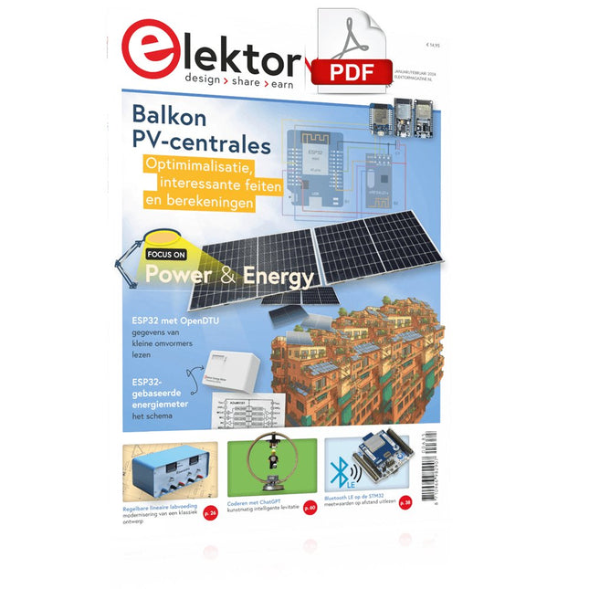
Elektor Digital Elektor Januari/Februari 2024 (PDF)
Elektor GREEN en GOLD leden kunnen deze uitgave hier downloaden. Nog geen lid? Klik hier om een lidmaatschap af te sluiten. Project-update: ESP32-gebaseerde energiemeterwe gaan verder met het prototype Optimalisatie van balkon PV-centralesoverwegingen, interessante feiten en berekeningen ESP32 met OpenDTU voor balkoncentralesgegevens van kleine omvormers via MCU’s uitlezen Regelbare lineaire labvoeding0...50 V / 0...2 A + dubbele symmetrische voeding Energieopslag – vandaag en morgeneen vraaggesprek met Simon Engelke 2024: een AI-odysseehet houdt nog lang niet op Bluetooth LE op de STM32meetwaarden op afstand uitlezen Mensvriendelijk slim keuken-voorraadsysteem MAUI: programmeren voor PC, tablet en smartphonehet nieuwe framework in theorie en praktijk ChatMagLevkunstmatig intelligente levitatie Eenvoudige PV-regelaarbouw je eerste, volledig functionele PV-energiebeheersysteem Koude-kathode-buizenvreemde onderdelen Uit het leven gegrepennostalgie Alle begin......bekijkt de FET CAN-bus voor de Arduino UNO R4: een tutorialtwee UNO R4’s nemen de bus! Elektor infographicvoeding en energie Vergelijking van vermogensdichtheid en vermogensefficiëntie Aluminium elektrolytische condensatorenstoringspotentieel in audiotechnologie USB testen en metenmet de Fnirsi FNB58 De Pixel Pump pick&place-tooleenvoudiger handmatige assemblage van SMT-printen Oost West Lab Bestnog niet zo lang geleden, in een land heel ver van hier... “In de wereld van ethiek in elektronica kunnen zelfs kleine stappen een aanzienlijke invloed hebben.” Ethiek in elektronicade OECD Guidelines en het Lieferkettensorgfaltspflichtengesetz Chadèche: slimme NiMH-(ont)laderlezersproject in het kort Project 2.0correcties, updates en brieven van lezers
€ 9,95
-
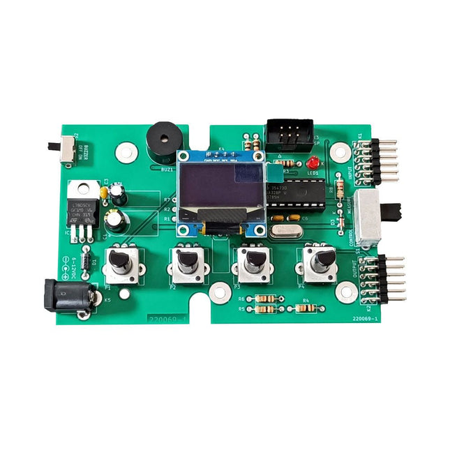
Elektor Labs Elektor Super Servo Tester Kit
The Elektor Super Servo Tester can control servos and measure servo signals. It can test up to four servo channels at the same time. The Super Servo Tester comes as a kit. All the parts required to assemble the Super Servo Tester are included in the kit. Assembling the kit requires basic soldering skills. The microcontroller is already programmed. The Super Servo Tester features two operating modes: Control/Manual and Measure/Inputs. In Control/Manual mode the Super Servo Tester generates control signals on its outputs for up to four servos or for the flight controller or ESC. The signals are controlled by the four potentiometers. In Measure/Inputs the Super Servo Tester measures the servo signals connected to its inputs. These signals may come from for instance an ESC, a flight controller, or the receiver or another device. The signals are also routed to the outputs to control the servos or the flight controller or ESC. The results are shown on the display. Specifications Operating modes Control/Manual & Measure/Inputs Channels 3 Servo signal inputs 4 Servo signal outputs 4 Alarm Buzzer & LED Display 0.96' OLED (128 x 32 pixels) Input voltage on K5 7-12 VDC Input voltage on K1 5-7.5 VDC Input current 30 mA (9 VDC on K5, nothing connected to K1 and K2) Dimensions 113 x 66 x 25 mm Weight 60 g Included Resistors (0.25 W) R1, R3 1 kΩ, 5% R2, R4, R5, R6, R7, R9, R10 10 kΩ, 5% R8 22 Ω, 5% P1, P2, P3, P4 10 kΩ, lin/B, vertical potentiometer Capacitors C1 100 µF 16 V C2 10 µF 25 V C3, C4, C7 100 nF C5, C6 22 pF Semiconductors D1 1N5817 D2 LM385Z-2.5 D3 BZX79-C5V1 IC1 7805 IC2 ATmega328P-PU, programmed LED1 LED, 3 mm, red T1 2N7000 Miscellaneous BUZ1 Piezo buzzer with oscillator K1, K2 2-row, 12-way pinheader, 90° K5 Barrel jack K4 1-row, 4-way pin socket K3 2-row, 6-way boxed pinheader S1 Slide switch DPDT S2 Slide switch SPDT X1 Crystal, 16 MHz 28-way DIP socket for IC2 Elektor PCB OLED display, 0.96', 128 x 32 pixels, 4-pin I²C interface Links Elektor Magazine Elektor Labs
€ 59,95€ 49,95Best Price
-

Elektor Special: Robotics and Automation
AI in Practice Dive into the fascinating world of robotics and automation! This Elektor Special shows you how to build your own robots with creativity, a little know-how, and affordable technology. From your first DIY project with Arduino or Raspberry Pi to intelligent systems with AI – this issue makes modern robotics understandable and accessible. Discover practical instructions, inspiring projects, and exciting insights into the maker scene. Learn how experimentation, community, and openness give rise to true innovation – and why robotics is so much more than just a technical hobby. Contents Imagination turns into reality Arduino-controlled Drawing Robot GalaxyRVR Mars Rover Kit for Arduino YDLIDAR X4Pro Lidar xHuskyLens AI Camera DOF Robot Arm with Raspberry Pi Pico Manufacturing Robots with Fischertechnik Pneumatic Industrial Robot Why Do We Keep Building Robot Dogs? Elektor Mini-Wheelie Robot Vehicles and Autonomous Driving
€ 19,95
Members: € 17,96


