
Search results for "fm or radio or kit"
-
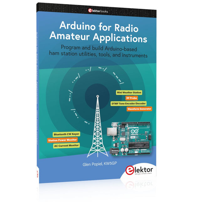
Elektor Publishing Arduino for Radio Amateur Applications
Program and build Arduino-based ham station utilities, tools, and instruments In addition to a detailed introduction to the exciting world of the Arduino microcontroller and its many variants, this book introduces you to the shields, modules, and components you can connect to the Arduino. Many of these components are discussed in detail and used in the projects included in this book to help you understand how these components can be incorporated into your own Arduino projects. Emphasis has been placed on designing and creating a wide range of amateur radio-related projects that can easily be built in just a few days. This book is written for ham radio operators and Arduino enthusiasts of all skill levels, and includes discussions about the tools, construction methods, and troubleshooting techniques used in creating amateur radio-related Arduino projects. The book teaches you how to create feature-rich Arduino-based projects, with the goal of helping you to advance beyond this book, and design and build your own ham radio Arduino projects. In addition, this book describes in detail the design, construction, programming, and operation of the following projects: CW Beacon and Foxhunt Keyer Mini Weather Station RF Probe with LED Bar Graph DTMF Tone Encoder DTMF Tone Decoder Waveform Generator Auto Power On/Off Bluetooth CW Keyer Station Power Monitor AC Current Monitor This book assumes a basic knowledge of electronics and circuit construction. Basic knowledge of how to program the Arduino using its IDE will also be beneficial.
€ 39,95
Members: € 35,96
-

FNIRSI FNIRSI TMP-610S (3-in-1) Multimeter (60,000 Counts) + Oscilloscope + Signal Generator
The FNIRSI TMP-610S is a compact 3-in-1 test instrument combining a True RMS multimeter, 10 MHz oscilloscope, and 50 kHz DDS signal generator. It is designed for electronics troubleshooting, circuit testing, and development in the lab or on the go. The multimeter offers 60,000-count resolution and supports voltage, current, resistance, capacitance, frequency, temperature, diode, and continuity measurements. The integrated oscilloscope provides real-time waveform analysis at up to 48 MSa/s, while the signal generator supports 13 waveform types with adjustable frequency, amplitude, and duty cycle. A 3.5-inch IPS touchscreen, smart auto-scan, Bluetooth connectivity for DMM functions, waveform storage, USB export, and a 3,000 mAh rechargeable battery make the TMP-610S a versatile all-in-one tool for electronics professionals and enthusiasts. Features 3-in-1 Design: DMM + Oscilloscope + Signal Generator 60,000-Count True RMS High-Precision Measurement 10 MHz Oscilloscope with 48 MSa/s Sampling Rate Bluetooth App Sync (Multimeter Function Only) 3.5-inch Smart Touchscreen with Multiple Display Modes 50 kHz DDS Signal Generator with 13 Waveforms Built-in Fuse for Easy Replacement Specifications Multimeter Function Range Accuracy DC voltage 600mV/6V/60V/600V/1000V ±(0.03%+5d) AC voltage 600mV/6V/60V /600V/750V ±(0.3%+15d) DC current 600uA/6000uA/60mA/600mA ±(0.15%+5d) 6A/10A ±(0.2%+5d) AC current 600uA/6000uA/60mA/600mA ±(0.5%+15d) 6A/10A ±(0.75%+15d) Resistance 600Ω/6KΩ/60KΩ/600KΩ/6MΩ ±(0.1%+5d) 60MΩ ±(0.2%+10d) Capacitance 60nF/600nF/6uF/60uF ±(2.5%+30d) 600uF/6mF/60mF ±(3.5%+30d Frequency 10 Hz~60 MHz ±(0.01%+5d) Temperature -40℃~1000℃ ±(1.0%+5℃) Continuity 0Ω~1KΩ ±(0.2%+5d) Diode 0V~3.0V, 0Ω~1 Ω ±(1%+5d) AC frequency response 10KHz / Oscilloscope Real-time Sampling Rate 48 MSa/s Analog Bandwidth 10 MHz Input Impedance 1MΩ Coupling Mode AC/DC Test Voltage Range 1:1 Probe - 80Vpp (±40V) 10:1 Probe - 800Vpp (±400V) Vertical Sensitivity 10mV/div~10V/div Vertical Displacement Adjustable with indication Horizontal Time Base Range 50 ns ~ 20 s Trigger Mode Auto, Normal, Single Trigger Type Rising, Falling, 50% Trigger Level Adjustable with indication Measurement Parameters Freq, Period, +Duty, ‒Duty, +Width, ‒Width, Max, Min, P‒P, Amp, RMS, Avg Persistence Off / 500ms / 1s / ∞ Cursor Measurement Yes Waveform Screenshot Saving Yes Signal Generator Output Waveform Supports 13 waveform types Frequency 0~50kHz Amplitude 0.0V~3.0V Duty Cycle 0~100%, adjustable for Square and Sawtooth waves Included 1x FNIRSI TMP-610S Multimeter + Oscilloscope + Signal Generator 1x P6100 Probe 1x Adapter 2x Alligator Clips 2x Multimeter Probes Probe Accessories 1x Storage Bag 1x USB-C Cable 1x Manual Downloads Manual
€ 179,95€ 149,95Best Price
-
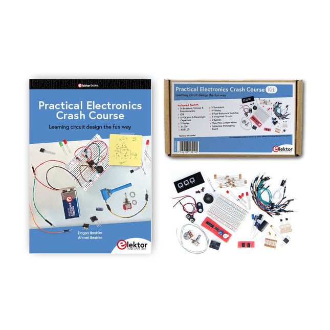
Elektor Bundles Practical Electronics Crash Course (Bundle)
Getting started in electronics is not as difficult as you may think. With this bundle (book + kit of parts), you can explore and learn the most important electrical and electronics engineering concepts in a fun way by doing various experiments. You will learn electronics practically without getting into complex technical jargon and long calculations. As a result, you will be creating your own projects soon. This kit contains the components required to build most of the detailed examples of the book on a breadboard and try them out for real. The kit can, of course, also be used without the book for building other circuits and doing your own experiments. Kit contents 1x 39 Ω, 1 W resistor 1x 47 Ω resistor 1x 180 Ω resistor 1x 330 Ω resistor 3x 1 kΩ resistor 1x 2.2 kΩ resistor 1x 3.9 kΩ resistor 1x 6.8 kΩ resistor 1x 10 kΩ resistor 1x 15 kΩ resistor 1x 22 kΩ resistor 1x 33 kΩ resistor 1x 47 kΩ resistor 1x 56 kΩ resistor 1x 82 kΩ resistor 1x 120 kΩ resistor 1x 680 kΩ resistor 2x 100 kΩ resistor 1x 10 kΩ trimmer 1x 10 kΩ linear potentiometer 1x 100 kΩ linear potentiometer 1x LDR 1x 1 nF ceramic capacitor 2x 10 nF ceramic capacitor 1x 100 nF ceramic capacitor 1x 1 µF, 25 V aluminium electrolytic capacitor 2x 10 µF, 25 V aluminium electrolytic capacitor 1x 100 µF, 25 V aluminium electrolytic capacitor 1x 470 µF, 25 V aluminium electrolytic capacitor 1x 1000 µF, 25 V aluminium electrolytic capacitor 1x RGB LED, Common-Cathode (CC) 1x 1N4148 small signal diode 1x 1N4733A 5.1 V, 1 W Zener diode 3x LED, red 2x BC337 NPN transistor 1x IRFZ44N N-channel MOSFET 2x NE555 timer 1x LM393 comparator 1x 74HCT08 quad AND gate 3x Tactile switch 2x SPDT switch 1x Relay, SPDT, 9 VDC 1x Active buzzer 1x Passive buzzer 50 cm Solid wire, 16 AWG, unjacketed 2x PP3 9 V battery clip 1x Breadboard 20x Jumper wire This bundle contains: Practical Electronics Crash Course Kit (valued at: €45) Book: Practical Electronics Crash Course (normal price: €45)
€ 89,95€ 69,95Best Price
-

Elektor Bundles Schnelleinstieg in die Elektronik (Bundle)
Der Einstieg in die Elektronik ist einfacher, als Sie denken! Mit diesem Bundle – bestehend aus Buch und Experimentierkit – entdecken Sie die Grundlagen der Elektro- und Elektroniktechnik Schritt für Schritt. Anhand spannender Experimente lernen Sie praxisnah und verständlich, ganz ohne komplizierte Fachbegriffe oder langwierige Berechnungen. So sind Sie schon bald in der Lage, Ihre eigenen Elektronikprojekte umzusetzen! Das Kit enthält alle notwendigen Komponenten, um die meisten im Buch beschriebenen Schaltungen direkt auf dem Steckbrett aufzubauen und praktisch zu erproben. Das Kit kann selbstverständlich auch ohne das Buch zum Aufbau anderer Schaltkreise und zur Durchführung eigener Experimente verwendet werden. Inhalt des Kits 1x 39 Ω, 1 W Widerstand 1x 47 Ω Widerstand 1x 180 Ω Widerstand 1x 330 Ω Widerstand 3x 1 kΩ Widerstand 1x 2,2 kΩ Widerstand 1x 3,9 kΩ Widerstand 1x 6,8 kΩ Widerstand 1x 10 kΩ Widerstand 1x 15 kΩ Widerstand 1x 22 kΩ Widerstand 1x 33 kΩ Widerstand 1x 47 kΩ Widerstand 1x 56 kΩ Widerstand 1x 82 kΩ Widerstand 1x 120 kΩ Widerstand 1x 680 kΩ Widerstand 2x 100 kΩ Widerstand 1x 10 kΩ Trimmer 1x 10 kΩ Linearpotentiometer 1x 100 kΩ Linearpotentiometer 1x LDR 1x 1 nF Keramikkondensator 2x 10 nF Keramikkondensator 1x 100 nF Keramikkondensator 1x 1 µF, 25 V Aluminium-Elektrolytkondensator 2x 10 µF, 25 V Aluminium-Elektrolytkondensator 1x 100 µF, 25 V Aluminium-Elektrolytkondensator 1x 470 µF, 25 V Aluminium-Elektrolytkondensator 1x 1000 µF, 25 V Aluminium-Elektrolytkondensator 1x RGB-LED, Common-Cathode (CC) 1x 1N4148 Kleinsignaldiode 1x 1N4733A 5,1 V, 1 W Zenerdiode 3x LED, rot 2x BC337 NPN-Transistor 1x IRFZ44N N-Kanal-MOSFET 2x NE555-Timer 1x LM393-Komparator 1x 74HCT08 Quad-AND-Gatter 3x Tastschalter 2x SPDT-Schalter 1x Relais, SPDT, 9 VDC 1x Aktiver Summer 1x Passiver Summer 50 cm Massivdraht, 16 AWG, ohne Mantel 2x PP3 9 V Batterieclip 1x Steckbrett 20x Überbrückungskabel Dieses Bundle enthält: Buch: Schnelleinstieg in die Elektronik (Einzelpreis: 45 €) Kit: Schnelleinstieg in die Elektronik (Wert: 45 €)
€ 89,95€ 69,95Best Price
-
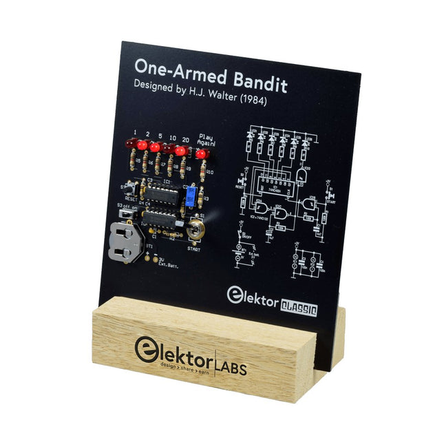
Elektor Labs Elektor One-armed Bandit
Pull Down Lever For Highest Score! This Elektor Circuit Classic from 1984 shows a playful application of CMOS 400x series logic ICs in combination with LEDs, a highly popular combination at the time. The project imitates a spinning-digit type slot machine. The Game To play the game, first agree on the number of rounds. Player 1 actuates the switch lever as long as desired and releases it. The LEDs then show the score which is the sum of the 50-20-10-5 digits lit up. If the Play Again! LED lights, Player 1 has another, “free” round. If not, it’s Player 2’s turn. The players keep tab of their scores, and the highest score wins. Features LEDs Indicate Score Multi-Player and Play Again! Elektor Heritage Circuit Symbols Tried & Tested by Elektor Labs Educational & Geeky Project Through-Hole Parts Only Included Printed Circuit Board All Components Wooden Stand Bill of Materials Resistors (5%, 250 mW) R1,R2,R3,R4 = 100kΩ R5,R6,R7,R8,R9,R10 = 1kΩ Capacitors C1 = 4.7nF, 10%, 50V, 5mm C2 = 4.7μF, 10%, 63V, axial C3,C4 = 100nF, 10 %, 50V, ceramic X7R, 5mm Semiconductors LED1-LED6 = red, 5mm (T1 3/4) IC1 = 74HC4024 IC2 = 74HC132 Miscellaneous S1 = switch, toggle, 21mm lever, SPDT, momentary S2 = switch, tactile, 24V, 50mA, 6x6mm S3 = switch, slide, SPDT IC1,IC2 = IC socket, DIP14 BT1 = PCB-mount CR2032 battery retainer clip Desktop Stand PCB 230098-1 Not included: BT1 = CR2032 coin cell battery
€ 39,95€ 15,98Best Price
-

Elektor Digital Hochfrequenz-Baubuch (PDF)
Die Hochfrequenztechnik ist eines der Gebiete, auf denen man auch heute noch eigene Ideen in die Tat umsetzen kann. Unzählige Schaltungsvarianten mit besonderen Zielsetzungen geben Raum für sinnvolle Experimente und Projekte. Vieles kann man nicht einfach kaufen. Detektorradios ohne eigene Energiequelle, einfache Röhrenempfänger mit einem Hauch von Nostalgie, die ersten Empfangsversuche mit dem Software Defined Radio oder Spezialempfänger für den Amateurfunk, all dies lässt sich mit wenig Aufwand realisieren. Lange Zeit war das Radiobasteln der Einstieg in die Elektronik. Inzwischen gibt es auch andere Wege, vor allem über Computer, Mikrocontroller und die Digitaltechnik. Allerdings kommen die analogen Wurzeln der Elektronik oft zu kurz. Die Radiotechnik eignet sich besonders gut als Lernfeld der Elektronik, weil man hier mit den einfachsten Grundlagen beginnen kann. Aber auch die Verbindung zur modernen Digitaltechnik liegt auf der Hand, wenn es z. B. um moderne Abstimmverfahren wie PLL und DDS oder um moderne DSP-Radios geht. Dieses Buch gibt einen Überblick und stellt eine Sammlung einfacher Projekte vor. Der Autor möchte Sie dabei unterstützen, eigene Ideen zu entwickeln, eigene Empfänger zu entwerfen und sie zu erproben.
€ 32,80
Members: € 29,52
-

Elektor Bundles 555 Timer Projects (Bundle)
This bundle is all about designing projects based on the 555 timer IC. The book features over 45 fully tested and documented projects. Together with the kit, which contains more than 130 through-hole components, you can build all the projects described on a breadboard. The setup also makes it easy to modify and experiment with the projects. Over 45 Builds for the Legendary 555 Chip (and the 556, 558) Some of the projects in the book are: Alternately Flashing Two LEDs Changing LED Flashing Rate Touch Sensor On/Off Switch Switch On/Off Delay Light-Dependent Sound Dark/Light Switch Tone Burst Generator Long Duration Timer Chasing LEDs LED Roulette Game Traffic Lights Continuity Tester Electronic Lock Switch Contact Debouncing Toy Electronic Organ Multiple Sensor Alarm System Metronome Voltage Multipliers Electronic Dice 7-Segment Display Counter Motor Control 7-Segment Display Dice Electronic Siren Various Other Projects Kit Contents Resistors 1x 15 kΩ 1x 68 kΩ 2x 47 kΩ 1x 82 kΩ 2x 820 Ω 1x 8.2 kΩ 3x 10 kΩ 1x 1.8 kΩ 1x 6.8 kΩ 14x 2.2 kΩ 10x 680 Ω 1x 27 kΩ 1x 5.6 kΩ 1x 560 kΩ 1x 4.7 kΩ 1x 3.3 kΩ 3x 33 kΩ 1x 36 kΩ 2x 100 kΩ 5x 1 kΩ 1x 3.9 kΩ 2x 56 kΩ 2x 12 kΩ 1x 10 kΩ potentiometer 1x 1 MΩ potentiometer 2x 50 kΩ potentiometer 3x 20 kΩ potentiometer 1x 10 kΩ potentiometer 1x 10 kΩ potentiometer 1x 50 kΩ potentiometer 1x 100 kΩ potentiometer 1x 50 kΩ potentiometer Capacitors 1x 0.33 μF 1x 1 μF 1x 10 nF 1x 22 nF 1x 47 nF 1x 100 nF 1x 10 μF electrolytic 1x 33 μF electrolytic 2x 100 μF electrolytic LEDs 10x 5 mm red LED 10x 3 mm red LED 3x 3 mm yellow LED 3x 3 mm green LED 1x Common-cathode 7-segment LED Semiconductors 3x 555 timer 1x CD4017 counter 1x CD4026 counter 1x CD4011 NAND gate 4x 1N4148 diode 1x IRFZ46N MOSFET 1x Thermistor 1x Light dependent resistor (LDR) Miscellaneous 1x Passive buzzer 1x Active buzzer 1x SG90 servo 1x 8 Ω mini loudspeaker 1x 9 V DC brushed motor 1x 5 V relay 1x 9 V battery clip 7x Pushbutton switches 1x Breadboard 1x Breadboard jumper wires
€ 69,95€ 54,95Best Price
-
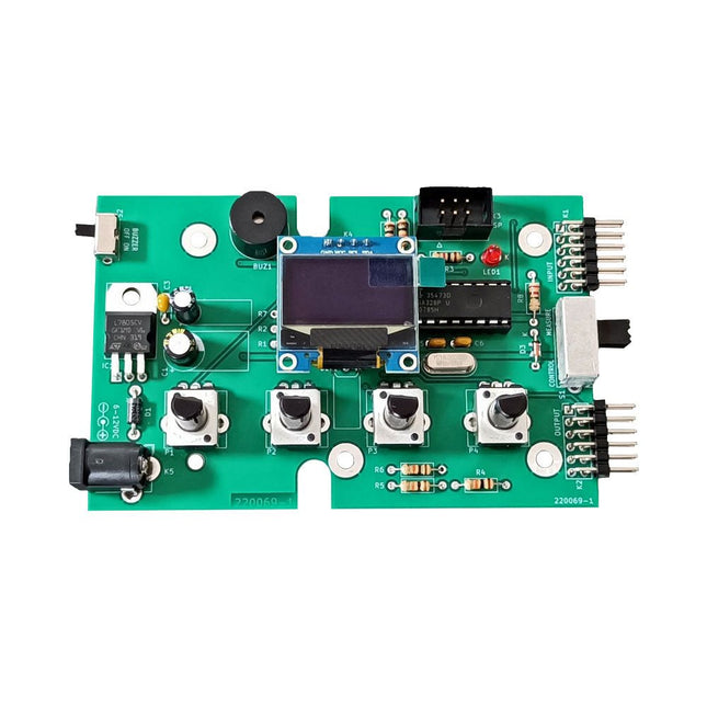
Elektor Labs Elektor Super Servo Tester Kit
The Elektor Super Servo Tester can control servos and measure servo signals. It can test up to four servo channels at the same time. The Super Servo Tester comes as a kit. All the parts required to assemble the Super Servo Tester are included in the kit. Assembling the kit requires basic soldering skills. The microcontroller is already programmed. The Super Servo Tester features two operating modes: Control/Manual and Measure/Inputs. In Control/Manual mode the Super Servo Tester generates control signals on its outputs for up to four servos or for the flight controller or ESC. The signals are controlled by the four potentiometers. In Measure/Inputs the Super Servo Tester measures the servo signals connected to its inputs. These signals may come from for instance an ESC, a flight controller, or the receiver or another device. The signals are also routed to the outputs to control the servos or the flight controller or ESC. The results are shown on the display. Specifications Operating modes Control/Manual & Measure/Inputs Channels 3 Servo signal inputs 4 Servo signal outputs 4 Alarm Buzzer & LED Display 0.96' OLED (128 x 32 pixels) Input voltage on K5 7-12 VDC Input voltage on K1 5-7.5 VDC Input current 30 mA (9 VDC on K5, nothing connected to K1 and K2) Dimensions 113 x 66 x 25 mm Weight 60 g Included Resistors (0.25 W) R1, R3 1 kΩ, 5% R2, R4, R5, R6, R7, R9, R10 10 kΩ, 5% R8 22 Ω, 5% P1, P2, P3, P4 10 kΩ, lin/B, vertical potentiometer Capacitors C1 100 µF 16 V C2 10 µF 25 V C3, C4, C7 100 nF C5, C6 22 pF Semiconductors D1 1N5817 D2 LM385Z-2.5 D3 BZX79-C5V1 IC1 7805 IC2 ATmega328P-PU, programmed LED1 LED, 3 mm, red T1 2N7000 Miscellaneous BUZ1 Piezo buzzer with oscillator K1, K2 2-row, 12-way pinheader, 90° K5 Barrel jack K4 1-row, 4-way pin socket K3 2-row, 6-way boxed pinheader S1 Slide switch DPDT S2 Slide switch SPDT X1 Crystal, 16 MHz 28-way DIP socket for IC2 Elektor PCB OLED display, 0.96', 128 x 32 pixels, 4-pin I²C interface Links Elektor Magazine Elektor Labs
€ 59,95€ 49,95Best Price
-

Elektor Classics The Elektor Audio Collection 2026 (USB Stick)
More than 475 Audio Circuits from 30 Years of Elektor This USB Stick contains over 475 different audio circuits from the volumes 1995-2025 of Elektor. The article search feature allows you to search full-text content. The results are always displayed as pre-formatted PDF documents. Highlights Surround-sound decoder Compact amp Sampling rate converter Battery powered preamplifier Titan 2000 amplifier Crescendo Millennium amplifier Audio-DAC/ADC IR-S/PDFI receiver and transmitter High-End Power Amp Hi-fi Wireless Headset Paraphase Tone Control and more… On the Stick you will also find a folder with additional material such as PCB layouts, Gerber files and software. Specifications Storage 16 GB Interfaces 1x USB-A1x USB-C System requirements PC with Adobe Reader 7.0 or higher Web browser
€ 49,95€ 39,95Best Price
-
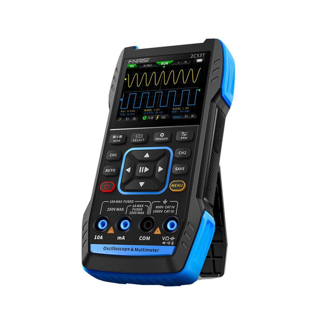
FNIRSI FNIRSI 2C53T (3-in-1) 2-ch Oscilloscope (50 MHz) + Multimeter + Signal Generator
The FNIRSI 2C53T, an enhanced version of its 10 MHz predecessor, is a compact and versatile 3-in-1 device. It combines a dual-channel 50 MHz oscilloscope, a 4.5-digit True RMS multimeter, and a signal generator with 13 waveform types, making it an essential tool for maintenance and research professionals. Oscilloscope: Features 50 MHz bandwidth, 250 MS/s sampling rate, ±400 V protection, FPGA + ARM + ADC architecture, and waveform saving for analysis. Multimeter: 4.5-digit True RMS with 19999 counts, supports AC/DC voltage, current, capacitance, resistance, diode, and continuity measurements. Signal Generator: Outputs 13 signal types up to 50 KHz, with adjustable frequency, amplitude, and duty cycle. With a 2.8-inch LCD, 3000 mAh battery (6-hour runtime), and a portable design, it delivers powerful functionality in a user-friendly package. Specifications Oscilloscope Channels 2 Analog Bandwidth 50 MHz Real-time Sampling Rate 250 MS/s Storage Depth 1 Kpts Impedance 1 MΩ Time Base Range 10ns-20s Vertical Sensitivity 10 mV/div-10 V/div (x1) Maximum Measured Voltage ±400 V Trigger Mode Auto/Normal/Single Trigger Type Rising edge, Falling edge Display Mode Y-T/Rolling/X-Y Coupling Method AC/DC Persistence OFF, 500ms, 1s, ∞ Math 8 Basic Operations + FFT Supported Waveform Screenshot Save, Export Waveform Image, Cursor Measurement, Infinite Afterglow Multimeter DC Voltage 1.9999V/19.999V/199.99V/1000V ±(0.5%+3) AC Voltage 1.9999V/19.999V/199.99V/750.0V ±(1%+3) DC Current 19.999mA/199.99mA/1.9999A/9.999A ±(1.2%+3) AC Current 19.999mA/199.99mA/1.9999A/9.999A ±(1.5%+3) Resistance 19.999MΩ/1.9999MΩ/199.99KΩ/19.999KΩ ±(0.5%+3) 1.9999KΩ/199.99Ω ±(2.0%+3) Capacitance 999.9uF/99.99uF/9.999uF/999.9nF/99.99nF/9.999nF ±(2.0%+5) 9.999mF/99.99mF ±(5.0%+20) Temperature −55~1300°C (−67~2372°F) ±(2.5%+5) Continuity Test Yes Diode Yes Signal Generator 13 Signal Waveforms Sine wave, rectangular wave, sawtooth wave, half wave, full wave, positive step wave, reverse step wave, exponential rise, exponential fall, DC, multi-audio, Sinker pulse, Lorentz wave Output Frequency 0-50 KHz Output Amplitude 0-3 V Output Duty Cycle 0-100% General Display 2.8" HD color screen Resolution 320 x 240 Charging USB-C (5 V/1 A) Battery 3000 mAh Lithium battery Standby Time 6 hours Languages English, Chinese Dimensions 167 x 89 x 35 mm Weight 300 g Differences New vs Old Version Model 2C53T Upgrade 2C53T Predecessor Bandwidth 50 MHz 10 MHz Display Mode Y-T/Rolling/X-Y Y-T/Rolling Math 8 Basic Operations + FFT N/A Cursor Function Yes N/A XY Lissau Graph Yes N/A Afterglow Function Yes N/A Multimeter Accuracy 19999 Counts 9999 Counts Signal Generator 50 KHz 2 MHz Included 1x FNIRSI 2C53T Oscilloscope (50 MHz) 2x P6100 Oscilloscope probes (10X) 1x Multimeter probe 1x Alligator clip probe 1x USB-C charging cable 1x Storage bag 1x Manual Downloads Manual Firmware V1.2.0
€ 119,95€ 94,95Best Price
-

Elektor Digital Retro Radio (NL) | E-book
Retro Radio is een praktijkboek voor beginners en uitermate geschikt voor iedereen die wel eens een radio zou willen bouwen en meer wil weten over de radiotechniek. Na een inleiding in de beginselen van de techniek en de radio-ontvangst op de korte golf komen een aantal eenvoudige radio-ontwerpen aan bod. Het gaat om radio’s voor de middengolf en korte golf, waarbij de KG radio’s geschikt zijn voor de ontvangst van Single Side Band signalen. Het “retro” karakter dankt het boek aan het feit dat de gepubliceerde schakelingen klassiekers zijn uit de analoge radiotechniek. Ze zijn geïnspireerd door schakelingen uit de jaren ’50 en de begintijd van de radiotechniek. De auteur grijpt terug op de radio in zijn meest elementaire vorm. Al het “overbodige” is uit de schakelingen weggelaten. Er wordt gewerkt met spoelen, afstemcondensatoren, keramische filters en spoelfilters. Alle schakelingen zijn gebouwd met gewone transistors en een veldeffecttransistor. Elektronische chips worden niet gebruikt. Overigens is aan de nieuwste ontwikkelingen niet helemaal voorbij gegaan. Er is ook een SDR ontwerp opgenomen. Een greep uit de schema’s: een kristalradio, verschillende middengolf ontvangers (ook met een radiobuis), een “oer” schema geïnspireerd door de begintijd van de radio, twee korte golf ontvangers met SSB (2-12 MHz en 6-17 MHz) en een ontvanger voor de 80 meter band. Verder is in dit boek bijzonder veel aandacht besteed aan de praktische constructie van de radio’s en zijn er verschillende eenvoudige meetapparaten beschreven die dienst kunnen doen bij het ontwerpen en testen van radio’s (meetzender, absorptiemeter, transistortester e.d.).
€ 24,95
Members: € 22,46
-

Elektor Digital Raspberry Pi für Funkamateure (PDF)
Mit RPi-basierten Tools und Messgeräten Amateurfunkstationen bauen und programmieren Obwohl viele Funkamateure immer noch mit klassischer HF- und Mobilfunkausrüstung arbeiten, ist der Einsatz von Computern und digitalen Techniken inzwischen sehr beliebt. Heutzutage kann jeder für ca. 40 € einen Raspberry Pi-Computer kaufen und fast jede Amateurfunk-Software auf dem 'RPi' ausführen. Die RTL-SDR-Geräte sind bei Funkamateuren sehr beliebt, weil sie sehr preiswert sind und viele Funktionen bieten. Ein Basissystem kann aus einem USB-basierten RTL-SDR-Dongle mit einer geeigneten Antenne, einem RPi-Computer, einem USB-basierten externen Audio-Eingangs-/ Ausgangsadapter und einer auf dem RPi installierten Software bestehen. Mit einer solch einfachen Einrichtung ist es möglich, Signale von etwa 24 MHz bis über 1,7 GHz zu empfangen. Dieses Buch richtet sich an Funkamateure, die lernen wollen, wie man mit dem Raspberry Pi elektronische Projekte baut. Das Buch eignet sich für die gesamte Bandbreite von Anfängern bis hin zu alten Hasen im Amateurfunk. Die schrittweise Installation des Betriebssystems wird mit vielen Details zu den gängigsten Linux-Befehlen beschrieben. Einige Kenntnisse der Programmiersprache Python sind erforderlich, um die im Buch beschriebenen Projekte zu verstehen und zu bearbeiten. Zu den im Buch entwickelten Beispielprojekten gehören eine Stationsuhr, ein Signalgenerator, der Entwurf eines Transistorverstärkers, der Entwurf eines aktiven Filters, ein Morsezeichen-Übungsgerät, ein Frequenzzähler, ein HF-Meter und vieles mehr. Für jedes Projekt werden das Blockdiagramm, der Schaltplan und der vollständige Python-Quellcode angegeben, einschließlich der vollständigen Beschreibung der Projekte. Neben der umfassenden Behandlung von RTL-SDR für Amateurfunk fasst das Buch auch die Installations- und Gebrauchsanweisungen der folgenden Amateurfunkprogramme zusammen, die Sie auf ihrem Raspberry Pi ausführen können: TWCLOCK, Klog, Gpredict, FLDIGI, DIRE WOLF, xcwcp, QSSTV, LinPsk, Ham Clock, CHIRP, xastir und CQRLOG.
€ 34,80
Members: € 31,32


