
Search results for "avr OR software OR defined OR radio OR 100182 OR 72"
-

Elektor Digital Elektor 11-12/2022 (PDF)
Diese Ausgabe steht allen GOLD- und GREEN-Mitgliedern auf der ElektorMagazine-Website zum Download bereit! Sie sind noch kein Mitglied? Hier klicken! High-End aus dem Elektor-Labor High-End-Verstärker Fortissimo-100Vollsymmetrische Audio-Endstufe mit 100/190 W Frequenzbestimmung unbekannter Schwingkreise und QuarzeTips & Tricks, Best Practices and Other Useful Information Platinen entwerfenTipps aus der Praxis Löten ….na und?Ein etwas genauerer Blick auf die heutige Löttechnik Bluetooth-Garagentorsteuerung mit niedriger LatenzSteuerung mit kurzen BLE-Nachrichten über ein Smartphone Ideal Diode Controller„Dioden“ mit geringer Verlustleistung LED-Girlanden mit ESP32 und FreeRTOSBlinken und variable Helligkeit Aller Anfang ...... muss nicht schwer sein: Es geht weiter mit den Z-Dioden UKW/DAB+-EmpfängerDas Beste aus beiden Welten Aus dem Leben gegriffenElectronica Obscura Software-Fehlern drahtlos auf der SpurZirkularer Puffer und Webserver auf dem ESP32 Hat Covid einen Innovationsschub im Ingenieurwesen ausgelöst?Innovative Bauteile, Komponenten und Lösungen 2022 Ersa i-CON TRACE – die IoT-Lötstation für Praktiker Infographics Was wollen wir mit all diesen Daten machen? Ansteuerung des E-Paper-Displays von Ynvisible Immer innovativ mit InnoFaithF&A mit Walter Arkesteijn Industrielle AutomatisierungEinfache und skalierbare IoT-Nachrüstungen Das Oszilloskop der nächsten Generation für schnellere EinblickeRohde & Schwarz präsentiert die R&S MXO 4 Serie Linear-Steckverbinder mit niedrigem Profil lösen Aufgaben im Multi-Signal-Datenmanagement Smart – Innovativ – KosteneffizientGateMate-FPGAs entwickelt und hergestellt in Deutschland Vom Layout zum Prototypen an einem Tag4-Lagen-PCBs im Elektronik-Labor Tools für die kostengünstige Sensorentwicklung Isolierter Analogausgang für Arduino Uno Betreten für Unbefugte verboten!Herr Karenovics entdeckt das Theremin electronica fast forward 2022 - powered by ElektorLine-up und Zeitplan SenderpeilungVerlorene Funk-Wettersensoren wiederfinden Das interne Rauschen eines ICs abschätzenMit einer einfachen Methode Ethik in AktionUnterstützt vom WEEF Ohne Ethik kein nachhaltiges GeschäftEin Interview mit Professor Stefan Heinemann Der WEEF-Index 2023 Filter-SoftwareDesign-Tools für analoge Filter TV-B-Gone!... oder zumindest: B-OFF RP2040-basierte Luftgütemessung Kickstart zu Python 3Ein Beispiel-Kapitel: Digitale Bildverarbeitung und Wand-Bibliothek PolyfusesBemerkenswerte Bauteile Hexadoku
€ 11,90
-

Elektor Digital Praxiskurs AVR-XMEGA-Mikrocontroller (E-book)
Die Mikrocontrollertechnologie ist eines der wichtigsten Gebiete der modernen Elektronik. Mikrocontroller haben sich in den letzten Jahren in allen Bereichen der modernen Technik etabliert. Der vorliegende Kurs gibt eine umfassende Einführung in die faszinierende Welt der Controllertechnik. Nach grundlegenden Betrachtungen zur Controllertechnologie wird bereits im ersten Teil des Kurses auf die praktische Umsetzung des Stoffes eingegangen. Als Basis dafür dient ein modernes Entwicklungsboard (XMEGA-A3BU Xplained), das mit einem der aktuellsten Controller des Herstellers Atmel ausgestattet ist. Der zweite Teil beschäftigt sich detailliert mit der Programmierung des Controllers. Hier kommt die Sprache „C“ zum Einsatz, da diese in der Firmware-Entwicklung eine dominierende Stellung einnimmt. Die bei weitem überwiegende Mehrheit der professionellen Entwicklungsarbeit wird in C ausgeführt. Diese Programmiersprache bietet eine umfassende Grundlage für alle Controlleranwendungen. Im dritten Teil des Kurses wird schließlich auf die hardwarenahe Programmierung eingegangen. Nach der Durchsprache von Pin-Ansteuerung, Takterzeugung und Oszillatoroptionen werden die anspruchsvolleren Themen wie Interrupts, Timer und Counter, Pulsweitenmodulation und Analog-Digitalwandlung behandelt. Der Kurs setzt auf die Philosophie des „Learning by Doing“. Er eignet sich dadurch hervorragend als praktische Ergänzung für Unterricht und Vorlesungen in Weiterführenden Schulen Technischen Berufsschulen und Fachakademien Fachhochschulen und Universitäten Aber auch der ambitionierte, nichtprofessionelle Anwender kann sich mit dem Lernmaterial einen Überblick über den neuesten Stand der Controllertechnik verschaffen.Umfangreiche Praxisbeispiele und Übungsprogramme runden den Kurs ab und lassen keine Fragen offen.
€ 34,80
Members: € 31,32
-

Red Pitaya Red Pitaya STEMlab 125-14 PRO Gen 2 Starter Kit (incl. Book)
This bundle includes the Red Pitaya STEMlab 125-14 PRO Gen 2 Starter Kit and the new book "Experimenting with Red Pitaya STEMlab Gen 2". The Red Pitaya STEMlab 125-14 PRO Gen 2 Starter Kit is a powerful and flexible platform for signal processing, data acquisition, and electronic measurement applications. Designed for engineers, developers, researchers, and educators, this kit provides everything required to start building advanced measurement and control systems. At the core of the kit is the STEMlab 125-14 PRO Gen 2 board, an upgraded and ultra-lightweight development platform. Powered by the Xilinx Zynq-7010 SoC with 512 MB of RAM, it combines FPGA programmability with ARM processing power to enable high-performance instrumentation and custom signal-processing solutions. The board offers 14-bit ADC and DAC resolution, a 125 MS/s sampling rate, an input range of ±20 V, and up to 60 MHz bandwidth. Its improved low-noise analog front-end, USB-C connectivity, and compact design make it suitable for demanding applications such as RF development, radar systems, photonics research, software-defined radio (SDR), and industrial automation. The Starter Kit includes all essential accessories for immediate use: a microSD card with preinstalled operating system, power supply, Ethernet cable for remote access, two 100 MHz oscilloscope probes, and SMA-to-BNC adapters for flexible signal connections. The Red Pitaya STEMlab 125-14 PRO Gen 2 Starter Kit is an excellent platform for rapid prototyping, FPGA development, measurement instrumentation, and advanced electronics experimentation. Features 14-bit ADC and DAC resolution 125 MS/s sampling rate ±20 V input range Up to 60 MHz bandwidth Xilinx Zynq-7010 SoC (FPGA + ARM processor) 512 MB RAM Low-noise analog front- and back-ends Applications RF development and testing Radar and wireless systems Software-defined radio (SDR) Photonics and optical research Industrial automation and control systems Signal analysis and instrumentation Rapid prototyping of electronic measurement systems Specifications Processor Dual-core ARM Cortex-A9 FPGA AMD Xilinx Zynq-7010 SoC RAM 512 MB (4 Gb) Storage microSD card (up to 32 GB) Operating System Linux-based Red Pitaya OS ADC Resolution 14-bit DAC Resolution 14-bit Bandwidth 60 MHz (DC) Sampling Rate 125 MS/s Analog Input Channels 2 Analog Output Channels 2 Input Voltage Range ±1 V (LV) / ±20 V (HV) Input Impedance 1 MΩ / 10 pF Output Voltage Range ±1 V Ethernet 1x Gigabit Ethernet (RJ45) USB 2x USB-C 2.0 (for power and console) Digital I/O 16x GPIO (3.3 V) Communication Interfaces I²C, SPI, UART, CAN Power Supply 5 V/3 A via USB-C Dimensions 106.8 x 60.0 x 17.9 mm Included 1x Red Pitaya STEMlab 125-14 PRO Gen 2 board 2x 100 MHz oscilloscope probes 2x SMA-to-BNC adapters 1x microSD card with preinstalled OS 1x USB-C Power supply 1x Ethernet cable Downloads Documentation Schematics Book: Experimenting with Red Pitaya STEMlab Gen 2 With this new book, Red Pitaya goes beyond a versatile board. It becomes a powerful laboratory instrument for precision measurement, analysis, and control. From the fundamentals of electronic project development, monitoring, control, and design to testing, this book walks you step-by-step through everything you need to know to harness the full potential of Red Pitaya hardware and software. The book presents real-time, FPGA-based projects that are developed on a PC using the Vivado environment, then transferred to the Red Pitaya for execution and testing. You will learn about enhanced performance, expanded I/O capabilities, improved FPGA features, and advanced connectivity options that open up new frontiers for precision measurement, monitoring, and control in your embedded applications. Inside the book you will discover: A deep dive into Red Pitaya architecture and hardware design Electronic experiments using Red Pitaya for measurement and monitoring Hands-on projects using the Python programming language Practical guidance for FPGA programming using Red Pitaya Red Pitaya FPGA projects using the Verilog HDL under Vivado IDE Practical design of electronic projects including measurement and testing Step-by-step examples that bridge theory and real-world implementation Whether you are designing your own electronic circuits, developing signal analysis tools, or creating real-time control or monitoring systems, this book provides you the knowledge and confidence you need to fully learn and customize the Red Pitaya platform.
€ 799,00
Best Price
-
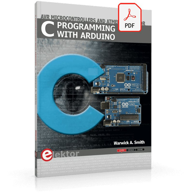
Elektor Digital C Programming with Arduino (E-book)
Technology is constantly changing. New microcontrollers become available every year. The one thing that has stayed the same is the C programming language used to program these microcontrollers. If you would like to learn this standard language to program microcontrollers, then this book is for you! Arduino is the hardware platform used to teach the C programming language as Arduino boards are available worldwide and contain the popular AVR microcontrollers from Atmel. Atmel Studio is used as the development environment for writing C programs for AVR microcontrollers. It is a full-featured integrated development environment (IDE) that uses the GCC C software tools for AVR microcontrollers and is free to download. At a glance: Start learning to program from the very first chapter No programming experience is necessary Learn by doing – type and run the example programs A fun way to learn the C programming language Ideal for electronic hobbyists, students and engineers wanting to learn the C programming language in an embedded environment on AVR microcontrollers Use the free full-featured Atmel Studio IDE software for Windows Write C programs for 8-bit AVR microcontrollers as found on the Arduino Uno and MEGA boards Example code runs on Arduino Uno and Arduino MEGA 2560 boards and can be adapted to run on other AVR microcontrollers or boards Use the AVR Dragon programmer/debugger in conjunction with Atmel Studio to debug C programs
€ 39,95
Members: € 35,96
-

Elektor Digital Mikrocontroller-Technik (PDF)
Mikrocontroller haben sich in den letzten Jahren in praktisch allen Bereichen der modernen Technik etabliert. In zunehmendem Maße dringen sie auch in die Gebiete der Künstlichen Intelligenz und der Robotertechnik vor. Das vorliegende Buch gibt eine umfassende Einführung in die Welt der Controller-Technik mit all ihren Facetten, von der einfachen Steuerung über die Sensor-Technik bis hin zur Datenübertragung in das Internet. Als Basis dafür dient das von Elektor entwickelte AVR-Playground-Board. Das Board kann mit Controllern der ATmega-Familie bestückt werden und ist mit dem bekannten Arduino-System kompatibel, so dass auch die verschiedenen Arduino-Hardware-Erweiterungen verwendet werden können. Für die Programmierung kommt die Sprache „C“ zum Einsatz. Auch hier wird im Buch auf das Arduino-System zurückgegriffen. Die frei verfügbare Arduino-Entwicklungsumgebung erlaubt den leichten Einstieg, ohne dass später Einschränkungen in Kauf genommen werden müssen. Die Hardware-nahe Programmierung steht dabei besonders im Fokus. Nach der Erläuterung von grundlegenden Anwendungen wird auf die anspruchsvolleren Themen wie Interrupts, Timer und Counter, Pulsweitenmodulation und Analog-Digital-Wandlung eingegangen. Praktische Anwendungen können sowohl mit einem Arduino als auch mit dem AVR-Playground-Board durchgeführt werden. Da das AVR-Playground-Board bereits über eine Vielzahl von Peripherie-Einheiten verfügt, sind nur noch wenige externe Bauteile erforderlich. Das Board kann im Elektor-Shop hier bezogen werden.
€ 32,80
Members: € 29,52
-

Elektor Publishing Mikrocontroller-Technik
Mikrocontroller haben sich in den letzten Jahren in praktisch allen Bereichen der modernen Technik etabliert. In zunehmendem Maße dringen sie auch in die Gebiete der Künstlichen Intelligenz und der Robotertechnik vor. Das vorliegende Buch gibt eine umfassende Einführung in die Welt der Controller-Technik mit all ihren Facetten, von der einfachen Steuerung über die Sensor-Technik bis hin zur Datenübertragung in das Internet. Als Basis dafür dient das von Elektor entwickelte AVR-Playground-Board. Das Board kann mit Controllern der ATmega-Familie bestückt werden und ist mit dem bekannten Arduino-System kompatibel, so dass auch die verschiedenen Arduino-Hardware-Erweiterungen verwendet werden können. Für die Programmierung kommt die Sprache „C“ zum Einsatz. Auch hier wird im Buch auf das Arduino-System zurückgegriffen. Die frei verfügbare Arduino-Entwicklungsumgebung erlaubt den leichten Einstieg, ohne dass später Einschränkungen in Kauf genommen werden müssen. Die Hardware-nahe Programmierung steht dabei besonders im Fokus. Nach der Erläuterung von grundlegenden Anwendungen wird auf die anspruchsvolleren Themen wie Interrupts, Timer und Counter, Pulsweitenmodulation und Analog-Digital-Wandlung eingegangen. Praktische Anwendungen können sowohl mit einem Arduino als auch mit dem AVR-Playground-Board durchgeführt werden. Da das AVR-Playground-Board bereits über eine Vielzahl von Peripherie-Einheiten verfügt, sind nur noch wenige externe Bauteile erforderlich. Das Board kann im Elektor-Shop hier bezogen werden.
€ 39,80
Best Price
-

Elektor Publishing 8-Bit-Mikrocontroller
PIC und AVR verstehen In diesem Buch werden wir uns ausschließlich mit 8-Bit-Mikrocontrollern beschäftigen, und zwar mit Mikrocontrollern der 8-Bit-PIC- und der 8-Bit-AVR-Mikrocontroller-Linien. Bei der PIC-Familie handelt es sich dabei um PIC10, PIC12, PIC16 und PIC18; bei der AVR-Familie um ATtiny, ATmega und ATxmega. Die vorgestellten 8-Bit-Chips sind für sehr viele Anwendungen vollkommen ausreichend und preislich auch attraktiv. Durch die Lektüre des Buches erhalten Sie ein fundiertes Wissen über die genannten 8-Bit-Mikrocontroller, über ihre Architektur, ihre Pinbelegungen und über ihre Programmierung. Weil wir uns in diesem Buch mit den Grundlagen der Architektur der PICs und AVRs vertraut machen möchten, werden wir auch für alle PIC- und AVR-Anwendungen Assembler einsetzen, denn die Assembler-Sprache erlaubt es, die Technik im Detail kennenzulernen. Wenn man wirklich wissen möchte, was sich im Mikrocontroller abspielt, greift man zu Assembler. Damit hat man die beste Gelegenheit, sehr nah an den Kern zu kommen. Und wenn man schon einen Mikrocontroller-Typ kennengelernt und verstanden hat, ist es bei dem nächsten deutlich einfacher, auch wenn er von einem anderen Hersteller kommt. Bei anderen Programmiersprachen bleibt die Technik immer ziemlich tief versteckt. Die Assembler-Beispiele sind so einfach gestaltet, dass sie jeder mit den im Buch aufgezeigten Programmiertechniken erstellen kann. Weil es sich um einfache Beispiele handelt, werden wir sie alle auf einer universellen Lochrasterplatine realisieren. Manche sind auch auf einem Experimentier-Breadboard umsetzbar.
€ 39,80
Best Price
-

Elektor Digital 8-Bit-Mikrocontroller (PDF)
PIC und AVR verstehen In diesem Buch werden wir uns ausschließlich mit 8-Bit-Mikrocontrollern beschäftigen, und zwar mit Mikrocontrollern der 8-Bit-PIC- und der 8-Bit-AVR-Mikrocontroller-Linien. Bei der PIC-Familie handelt es sich dabei um PIC10, PIC12, PIC16 und PIC18; bei der AVR-Familie um ATtiny, ATmega und ATxmega. Die vorgestellten 8-Bit-Chips sind für sehr viele Anwendungen vollkommen ausreichend und preislich auch attraktiv. Durch die Lektüre des Buches erhalten Sie ein fundiertes Wissen über die genannten 8-Bit-Mikrocontroller, über ihre Architektur, ihre Pinbelegungen und über ihre Programmierung. Weil wir uns in diesem Buch mit den Grundlagen der Architektur der PICs und AVRs vertraut machen möchten, werden wir auch für alle PIC- und AVR-Anwendungen Assembler einsetzen, denn die Assembler-Sprache erlaubt es, die Technik im Detail kennenzulernen. Wenn man wirklich wissen möchte, was sich im Mikrocontroller abspielt, greift man zu Assembler. Damit hat man die beste Gelegenheit, sehr nah an den Kern zu kommen. Und wenn man schon einen Mikrocontroller-Typ kennengelernt und verstanden hat, ist es bei dem nächsten deutlich einfacher, auch wenn er von einem anderen Hersteller kommt. Bei anderen Programmiersprachen bleibt die Technik immer ziemlich tief versteckt. Die Assembler-Beispiele sind so einfach gestaltet, dass sie jeder mit den im Buch aufgezeigten Programmiertechniken erstellen kann. Weil es sich um einfache Beispiele handelt, werden wir sie alle auf einer universellen Lochrasterplatine realisieren. Manche sind auch auf einem Experimentier-Breadboard umsetzbar.
€ 32,80
Members: € 29,52
-
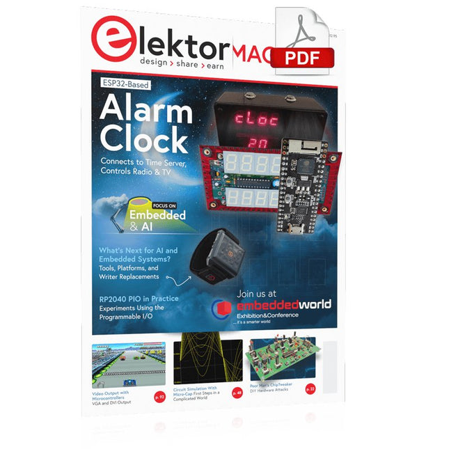
Elektor Digital Elektor March/April 2023 (PDF)
Elektor GREEN and GOLD members can download their digital edition here. Not a member yet? Click here. Cloc 2.0The Alarm Clock You've Always Wanted RP2040 PIO in PracticeExperiments Using the RP2040’s Programmable I/O Poor Man's ChipTweakerWe Have (Low-Budget) Ways of Making You Talk USB True Random Number GeneratorTwo PICs for the Price of One AVR Pimp My MicSelf-Designed Level Booster FFT with a MaixduinoFrequency spectrum display From Life’s ExperienceDesign Logic (or Non-Logic) UCN5804 Stepper Motor DriverPeculiar Parts, the Series Circuit Simulation With Micro-CapFirst Steps in a Complicated World PAUL Award 2022Young Technical Talents and Their Creative Solutions My First Software-Defined RadioBuilt in Less Than 15 Minutes Microcontroller Documentation Explained (Part 1)Datasheet structure What’s Next for AI and Embedded Systems?Tools, Platforms, and Writer Replacements Digitizing Vertical Farming Infographics: Embedded and AI Today and Tomorrow An Introduction to TinyML JetCarrier96A Versatile NVIDIA Jetson Development System Case Study: Taking EV Charging Global with a Universal RFID Solution High-Performance in Every ClassComputer-on-Module Standards Starting Out in ElectronicsLet’s Get Active! I²C Communication Using Node.js and a Raspberry PiSee Your Sensor Data in a Browser Video Output with Microcontrollers (2)VGA and DVI Output The Metronom Real-Time Operating SystemAn RTOS for AVR Processors DVI on the RP2040An Interview with Luke Wren, Chip Developer at Raspberry Pi Display HAT MiniShow the Weather Forecast on Raspberry Pi! WEEF 2022 Awards: Celebrate the Good Hexadoku
€ 7,50
-

OWON OWON XDG2035 2-ch Arbitrary Waveform Generator (35 Mhz)
The 2-channel OWON XDG2035 is a function/waveform generator that can generate signals with a maximum frequency of 35 Hz. The generator has a resolution of 1 µHz and a sample rate of 500 MSa/s. The OWON XDG2035 is capable of generating 6 standard waveforms and 150 arbitrary waveforms. With the included software you can write advanced functions up to 10 million points. Waveforms can be saved to the function generator's internal memory using a PC via USB or LAN. The OWON XDG2035 also supports SCPI commands and LabView. The function generator has an integrated high-quality frequency counter, which can operate from 100 to 200 MHz. Features Max. 35 MHz frequency output 500 MSa/s Sample rate, Vertical resolution 1μHz 14 bits Vertical Resolution, 10 Marb waveform length Comprehensive waveform output: 6 basic waveforms,and 150 built-in arbitrary waveforms Comprehensive modulation functions: AM, FM, PM, FSK, 3FSK, 4FSK, PSK, OSK, ASK, BPSK, PWM, Sweep, and Burst High-accuracy frequency counter integrated, supported range 100-200 MHz SCPI and LabVIEW supported 7 inch multi-touch screen (800 x 480 pixels) Specifications Channel 2 Frequency Output 35 MHz Sample Rate 500 MSa/s Vertical Resolution 14 bits Waveform Standard Waveform sine, square, pulse, ramp, noise, and harmonic Arbitrary Waveform exponential rise, exponential fall, sin(x)/x, step wave, and others, total 150 built-in waveforms, and user-defined arbitrary waveform Frequency (resolution 1 μHz) Sine 1 μHz-100 MHz Square 1 μHz ~ 30 MHz Pulse 1 μHz ~ 25 MHz Ramp 1 μHz ~ 3 MHz Noise (-3 dB, typical) 100 MHz Arbitrary Waveform 1 μHz ~ 15 MHz Harmonic 1 μHz ~ 50 MHz Accuracy ±2ppm, 25°C ±5°C Waveform Length 2 points - 10M points Amplitude Into 50Ω load 1mVpp ~ 10Vpp (≤25 MHz); 1mVpp ~ 5Vpp (≤60 MHz); 1mVpp ~ 2.5Vpp (≤100 MHz) Modulation Type AM, DSB-AM, FM, PM, ASK, FSK, PSK, BPSK, QPSK, 3FSK, 4FSK, OSK, PWM, SUM Frequency Counter Function Frequency, period, +width, -width, +duty, and -duty Frequency Range 100 ~ 200 MHz Frequency Resolution 7 digits Input/Output Input mode frequency counter, external modulation input, external trigger input, internal clock output, external reference clock input/output Communication Interface USB Host, USB Device, LAN, RS232 (optional) Mechanical specifications Dimensions 340 x 177 x 90 mm Weight 2.3 kg Included 1x OWON XDG2035 1x Power Cord 1x CD-ROM 1x Quick start guide 1x USB Cable 1x BNC-BNC Cable Downloads Quick Guide
€ 339,00
-
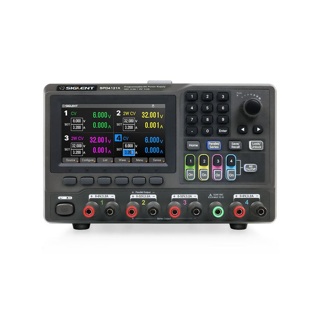
Siglent Siglent SPD4121X 4-ch DC Power Supply (285 W)
The Siglent SPD4121X is a 4-channel DC Linear Programmable Power Supply equipped with a 4.3-inch TFT-LCD display, friendly human-machine interface, and excellent performance indicators. Real-time waveform display provides engineers with an informative user interface. SPD4121X offers a total output power of 285 W with a resolution of 1 mV/1 mA. The maximum voltage and current for each channel are as follows: CH1: 15 V/1.5 A CH2: 12 V/10 A CH3: 12 V/10 A CH4: 15 V/1.5 A Features Rated output power: 285 W Rated voltage: 32 V, 12 V, 30 V Up to four high-precision power supplies with independent controllable outputs, supporting CH2 and CH3 series and parallel connections Clear graphical interface with waveform and timer display modes 5-digit voltage and current display with minimum resolution of 1 mV, 1 mA Fast output response time: <50us The high current channel support remote voltage compensation sense function. The maximum compensation voltage is 0.6 V Overvoltage protection and overcurrent protection or safe and accurate operation Equipped with a 4.3-inch TFT-LCD display (480 x 272 resolution) USB and LAN standard communication USB-GPIB module is optional Excellent channel density with up to 4 channels in a 3U half rack package Internal data storage for setups and parameters Embedded Web Server with instrument communication that doesn’t require software installation Fully SCPI programming command set support as well as a LabView driver for remote control and system automation Specifications SPD4323X SPD4121X SPD4306X Channel Output CH1: Voltage 0 to 6 V Current 0 to 3.2 ACH2: Voltage 0 to 32 V Current 0 to 3.2 ACH3: Voltage 0 to 32 V Current 0 to 3.2 ACH4: Voltage 0 to 6 V Current 0 to 3.2 A CH1: Voltage 0 to 15 V Current 0 to 1.5 ACH2: Voltage 0 to 12 V Current 0 to 10 ACH3: Voltage 0 to 12 V Current 0 to 10 ACH4: Voltage 0 to 15 V Current 0 to 1.5 A CH1: Voltage 0 to 15 V Current 0 to 1.5 ACH2: Voltage 0 to 30 V Current 0 to 6 ACH3: Voltage 0 to 30 V Current 0 to 6 ACH4: Voltage 0 to 15 V Current 0 to 1 A Resolution 1 mV, 1 mA 1 mV, 1 mA 1 mV, 1 mA Setting Accuracy Voltage: ±(0.03% of reading+10) mV, Current: ±(0.3% of reading+10) mA Voltage: ±(0.03% of reading+10) mV, Current: ±(0.3% of reading+10) mA Voltage: ±(0.03% of reading+10) mV, Current: ±(0.3% of reading+10) mA Readback Accuracy Voltage: ±(0.03% of reading+10) mV, Current: ±(0.3% of reading+10) mA Voltage: ±(0.03% of reading+10) mV, Current: ±(0.3% of reading+10) mA Voltage: ±(0.03% of reading+10) mV, Current: ±(0.3% of reading+10) mA Display 4.3" TFT-LCD 5-digit voltage and current display 4.3" TFT-LCD 5-digit voltage and current display 4.3" TFT-LCD 5-digit voltage and current display Output power 240 W 285 W 400 W Included 1x Siglent SPD4121X Power Supply 1x Power cord (EU) 1x Output test cord (3 A) 1x USB cable 1x Quick start guide Downloads Datasheet Manual Quick start
€ 871,20
-

FNIRSI FNIRSI SG-003A Signal Generator
The FNIRSI SG-003A multi-functional Signal Generator a.k.a. Process Meter/Calibrator is a high-precision voltage/current generator and meter. The SG-003A provides highly accurate reference voltages or currents for testing and calibrating other measurement instruments like multimeters and oscilloscopes. Besides voltages and currents, the SG-003A also generates rectangular pulse signals with precisely programmable frequencies and duty cycles. Its converter mode turns the SG-003A into a precision voltage-controlled current source, or current-controlled voltage source, and even a voltage- or current-controlled frequency generator. The SG-003A is a great tool for checking your multimeter’s accuracy and precision, and for testing e.g. LEDs. Features Accuracy (voltage/current) 0.1% ±0.005 Resolution (current) 0.01 mA Frequency 0-10 kHz Resolution 5 digits Output power 24 V Display 2.4" TFT LCD (320 x 240) Dimensions 92 x 72 x 30 mm Weight 165 g Specifications Signal Range Precision Resolution Max load External power supply Active current output 0~24 mA ±(0.1% + 0.005) 0.01 mA 750 Ω Passive current output (XMT) 0~24 mA ±(0.1% + 0.005) 0.01 mA 0~30 V Voltage output 0~24 V ±(0.1% + 0.005) 0.01 V 24 V loop 0~24 mA ±(0.1% + 0.005) 0.01 mA Frequency output 0~9999 Hz ±2% 5 digits Current input 0~24 mA ±(0.1% + 0.005) 0.01 mA Voltage input 0~30 V ±(0.1% + 0.005) 0.01 V Included 1x FNIRSI SG-003A Signal generator 4x Test clips 1x USB charger 1x USB-C cable 1x Manual Downloads Manual Firmware V4.3
€ 69,95


