
Search results for "pdf OR download OR fr OR 02 OR 2002"
-
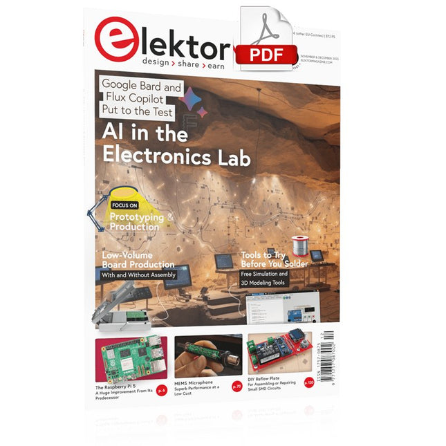
Elektor Digital Elektor November/December 2023 (PDF)
Elektor GREEN and GOLD members can download their digital edition here. Not a member yet? Click here. The Raspberry Pi 5A Huge Improvement From Its Predecessor AI in the Electronics LabGoogle Bard and Flux Copilot Put to the Test Arduino Nano Waveform GeneratorNano + Code = Function Generator Solar-Powered Christmas GarlandAn Eco-Friendly Solution for Garnishing Your Balcony USB Killer DetectorBetter Safe Than Sorry A Simple CNCed EnclosureWith Autodesk Fusion 360 for Personal Use Low-Volume Board ProductionWith and without Assembly IoT Simulation Simplified with WokwiDeveloper Uri Shaked on Design, Software, and More A Bare-Metal Programming Guide (Part 3)CMSIS Headers, Automatic Testing, and a Web Server LoRa, a Swiss Army Knife (2)The Hardware and Software MEMS Microphone Design and Construction Tools to Try Before You SolderSimulation and 3D Modeling Tools That Can Be Used for Free New Tools From Microchip!PICkit 5 and MPLAB ICD 5 Available Now! Rapid Prototyping of Flexible, Stretchable ElectronicsHow the Voltera NOVA Speeds Up Innovation in Wearable Electronic Systems Galvanic IsolationUsing Phototransistor Optocouplers Successfully The Complex Solution or the Anybus Solution?Embedded Industrial Ethernet in 2 Days Rather Than Many Months Your Essential DFM ChecklistHow to Start Designing for Manufacture 3D Printing FilamentsTypes, Features and Use in Prototyping Specialists for Effective Signal Analysis from ELF to EHF BandAaronia’s latest real-time SPECTRAN® V6 series spectrum analyzers Challenges of DFM Analysis for Flex and Rigid-Flex Design Setting Up an SMT Line The Right Combination for a Reliable Assembly Revolutionizing IndustriesThe Rise of Autonomous Mobile Robots (AMRs) Evolved for More ChallengesRohde & Schwarz Adds Eight-Channel R&S MXO 5 to Next-Generation Oscilloscopes Starting Out in Electronics……Amplifying Differences Mini Reflow PlateFor Assembling or Repairing Small SMD Circuits Don’t Start with a Prototype – Start with a Pretotype!Check That a Market Exists for Your Product Before Warming Your Soldering Iron 2023: An AI OdysseyGetting Help Designing a Physical Project Brussels Is InnovatingSupport for Deep Tech
€ 7,50
-

Siglent Siglent SDS2102X Plus 2-ch Oscilloscope (100 MHz)
Siglent's SDS2000X Plus series Digital Storage Oscilloscopes are available in bandwidths of 100 MHz, 200 MHz, and 350 MHz, have a maximum sample rate of 2 GSa/s, a maximum record length of 200 Mpts/ch, and up to 4 analog channels + 16 digital channels mixed-signal analysis ability. The SDS2000X Plus series employs Siglent’s SPO technology with a maximum waveform capture rate of up to 120,000 wfm/s (normal mode, up to 500,000 wfm/s in Sequence mode), 256-level intensity grading display function plus a color temperature display mode. It also employs an innovative digital trigger system with high sensitivity and low jitter. The trigger system supports multiple powerful triggering modes including serial bus triggering. History waveform recording, Sequence acquisition, Search and Navigate functions allow for extended waveform records to be captured, stored, and analyzed. An impressive array of measurement and math capabilities, options for a 50 MHz waveform generator, as well as serial decoding, mask test, bode plot, and power analysis are also features of the SDS2000X Plus. A 10-bit acquisition mode helps to satisfy applications that require more than 8-bit resolution. The large 10.1’’ capacitive touch screen supports multi-touch gestures, while the remote web control, mouse and external keyboard support greatly improve the operating efficiency of the SDS2000X Plus. Features 100 MHz, 200 MHz, 350 MHz (upgradable to 500 MHz) models Real-time sampling rate up to 2 GSa/s Record length up to 200 Mpts Serial bus triggering and decoder, supports I²C, SPI, UART, CAN, LIN, CAN FD, FlexRay, I²S and MIL-STD-1553B Provide 10 bit mode, Vertical and Horizontal Zoom Capacitive touch screen supports multi-touch gestures Siglent SDS2000X Plus Oscilloscopes SDS2102X Plus SDS2104X Plus SDS2204X Plus SDS2354X Plus Bandwidth 100 MHz 100 MHz 200 MHz 350 MHz Channels 2 4 4 4 Real-time sampling rate 2 GSa/s 2 GSa/s 2 GSa/s 2 GSa/s Capture rate 120,000 wfm/s 120,000 wfm/s 120,000 wfm/s 120,000 wfm/s Memory depth 200 Mpts/ch 200 Mpts/ch 200 Mpts/ch 200 Mpts/ch Included Siglent SDS2102X Plus Oscilloscope Passive probes Power cord USB cable Manual Downloads Datasheet Manual Quick guide Manual Firmware
€ 855,20
-
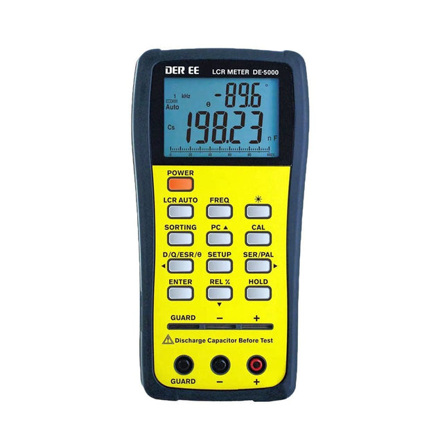
DER EE DER EE DE-5000 LCR Meter (100 kHz)
The DE-5000 is a smart, high-accurate, flexible and easy-to-use portable LCR meter. It features automatic LCR check, 4-wire Kelvin measurement, backlit display with 19999/1999 counts, multiple measurement modes and selectable test frequencies (100 Hz, 120 Hz, 1 kHz, 10 kHz or 100 kHz). The DE-5000 LCR meter is a practical helper for engineers or technicians. Features Auto L.C.R. check Ls/Lp/Cs/Cp/Rs/Rp/DCR with D/Q/θ/ESR measurement 4-wire Kelvin measurement 20,000 / 2,000 counts display Backlight Relative mode Series / Parallel modes Components sorting function Low battery indication Auto power off Specifications Test frequency 100 Hz / 120 Hz / 1 kHz / 10 kHz / 100 kHz Resistance range 20.000 Ω – 200.0 MΩ DCR range 200.00 Ω – 200.0 MΩ Capacitance range 200.00 pF – 20.00 mF Inductance range 20.000 µH – 2.000 KH Display (backlit LCD) 19999 / 1999 counts Selectable tolerance ±0.25%, ±0.5%, ±1%, ±2%, ±5%, ±10%, ±20% Power supply 9 V battery Dimensions 188 x 95 x 52 mm Weight 350 g (excluding battery) Included DE-5000 LCR meter Alligator test lead case (TL-21) AC/DC adaptor Guard line (TL-23) TL-22 SMD tweezers 9 V battery Carrying case Manual Downloads Datasheet
€ 192,39
-
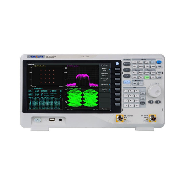
Siglent Siglent SSA3021X Plus Spectrum Analyzer (9 kHz – 2.1 GHz)
The Siglent SSA3021X Plus spectrum analyzer is a powerful and flexible tool for RF signal and network analysis. With a frequency range of 2.1 GHz, the analyzer delivers reliable automatic measurements and multiple modes of operation: spectrum analyzer the base, optional functions include RF power measurement, vector signal modulation analysis, reflection measurement, and EMI test. Applications include broadcast monitoring/evaluation, site surveying, S-parameter measurement, analog/digital modulation analysis, EMI pre-compliance test, research and development, education, production, and maintenance. Features Spectrum Analyzer Frequency Range from 9 kHz to 2.1 GHz –161 dBm/Hz Displayed Average Noise Level (Typ.) –98 dBc/Hz. @ 10 kHz Offset Phase Noise (1 GHz, Typ.) Level Measurement Uncertainty <0.7 dB (Typ.) 1 Hz Minimum Resolution Bandwidth (RBW) Preamplifier (Std.) Tracking Generator (incl. free of charge) Analog and Digital Signal Modulation Analysis Mode (opt.) Reflection Measurement Kit (opt.) EMI Filter and Quasi-Peak Detector Kit (opt.) Advanced Measurement Kit (opt.) 10.1-inch Multi-Touch Screen , Mouse and Keyboard supported Web Browser Remote Control on PC and Mobile Terminals and File Operation Specifications SSA3015X Plus SSA3021X Plus SSA3032X Plus SSA3075X Plus Frequency Range 9 kHz ~ 1.5 GHz 9 kHz ~ 2.1 GHz 9 kHz ~ 3.2 GHz 9 kHz ~ 7.5 GHz Resolution Bandwidth 1 Hz ~ 1 MHz 1 Hz ~ 1 MHz 1 Hz ~ 1 MHz 1 Hz ~ 3 MHz Phase Noise <–99 dBc/Hz <–98 dBc/Hz <–98 dBc/Hz <–98 dBc/Hz Total Amplitude Accuracy <1.2 dB <0.7 dB <0.7 dB <0.7 dB Display Average Noise Level –156 dBm/Hz –161 dBm/Hz –161 dBm/Hz –165 dBm/Hz Included Siglent SSA3021X Plus spectrum analyzer USB cable Power cord Quick start guide Downloads Datasheet Manual Documentation Firmware
€ 1.777,49
-

tinySA tinySA Ultra+ ZS407 Spectrum Analyzer
The tinySA Ultra+ ZS-407 is a compact, handheld spectrum analyzer and signal generator. Covering 100 kHz to 7.3 GHz in Ultra mode, it lets you visualize and analyze RF signals from HF right through many modern wireless bands – and can even spot signals up to ~12 GHz thanks to harmonic tracking. The intuitive 4-inch resistive touchscreen and rechargeable battery make it great for fieldwork, while features like a built-in signal generator, switchable bandpass filters, step attenuator, USB-PC control and auto-calibration add serious versatility. Features Screen size: 4 inch (480 x 320) Spectrum Analyzer for 0.1-900 MHz or, with Ultra mode enabled up to 7.3 GHz, level calibrated up to 7.3 GHz. Can observe signals up to 12 GHz Signal Generator with sine wave output between 0.1-900 MHz or square wave up to 6.3 GHz or RF test signal output up to 7.3 GHz when not used as Spectrum Analyzer. Switchable resolution bandpass filters from 200 Hz to 850 kHz Built-in 20 dB optional LNA Color display showing max 450 points providing gapless covering up to the full frequency range. MicroSD card slot for storing measurements, settings and screen captures. Specifications (Spectrum Analyzer) Input frequency range from 100 kHz to 900 MHz in normal mode and up to 7.3 GHz with ULTRA mode enabled Input impedance 50 ohm when input attenuation set to 10 dB or more. Selectable manual and automatic input attenuation between 0 dB and 31 dB in 1 dB steps when LNA not active Maximum +/-5V DC input Absolute maximum input level of +6 dBm with 0 dB internal attenuation Absolute maximum short term peak input power of +20 dBm with 30 dB internal attenuation Suggested maximum input power of +0 dBm with internal attenuation in automatic mode For best measurements keep input power below -25 dBm Input Intercept Point of third order modulation products (IIP3) of +15 dBm with 0 dB internal attenuation 1 dB compression point at -1 dBm with 0 dB internal attenuation Power detector resolution of 0.5 dB and linearity versus frequency of ±2 dB below 5.3 GHz, ±5dB between 5.3 GHz and 6 GHz Minimum burst length for correct level measurement at 850 kHz RBW in zero span mode of 50 microseconds Absolute power level accuracy after power level calibration of ±2 dB Built-in optional 20 dB LNA with Noise Figure of 5 dB up to 6 GHz Lowest discernible signal without LNA at 30 MHz using a resolution bandwidth of 30 kHz of -102 dBm Lowest discernible signal with LNA at 30 MHz using a resolution bandwidth of 200 Hz of -145 dBm Frequency accuracy equal to the selected resolution bandwidth Phase noise at 30 MHz of -108 dB/Hz at 100 kHz offset and -115 dB/Hz at 1MHz offset Spur free dynamic range when using a 30 kHz resolution bandwidth of 70 dB Resolution filters with a width of 0.2, 1, 3, 10, 30, 100, 300, 600 and 850 kHz On screen resolution of 51, 101, 145, 290 or 450 measurement points. Scanning speed of over 1000 points/second using largest resolution filters. Automatic optimization of actual scanning points to ensure coverage of the whole scan range regardless of the chosen resolution bandwidth Spur suppression option for assessing if certain signals are internally generated or actually present in the input signal Headphone output for listening to the demodulated audio (AM only). Stereo connector with or without microphone, high impedance is louder, short protected Specifications (Signal Generator) Sine wave output with harmonics below -40 dB of fundamental from 100 kHz to 900 MHz Output level selectable in 1 dB steps between -115 dBm and -19 dBm Above 800 MHz choice of two output modes: Cleanest signal mode: square wave, up to 6 GHz with coarse frequency steps and less accurate output level Highest accuracy mode: reduced harmonics with possibly strong spurs up to 7.3 GHz with frequency resolution equal to below 800 MHz and fine output level steps Level accuracy ±2 dB up to 800 MHz between -72 dBm and -19 dBm, less accuracy below -72 dBm, even less accuracy below -110 dBm Output frequency resolution 57.2 Hz Optional AM or FM modulation frequencies between 50 Hz and 5 kHz (AM) or 1 kHz (FM) or sweep over selectable frequency span AM modulation depth between 10% and 100% FM deviation between 1 kHz and 300 kHz Optional output level sweep over maximum the entire output level range Included 1x tinySA Ultra+ ZS407 Spectrum Analyzer 2x SMA connection cables 1x Barrel connector 1x Antenna with SMA connector 1x USB-C cable 1x microSD card (32 GB) Downloads Wiki
€ 196,02
-

Red Pitaya Red Pitaya STEMlab 125-14 PRO Gen 2 Starter Kit (incl. Book)
This bundle includes the Red Pitaya STEMlab 125-14 PRO Gen 2 Starter Kit and the new book "Experimenting with Red Pitaya STEMlab Gen 2". The Red Pitaya STEMlab 125-14 PRO Gen 2 Starter Kit is a powerful and flexible platform for signal processing, data acquisition, and electronic measurement applications. Designed for engineers, developers, researchers, and educators, this kit provides everything required to start building advanced measurement and control systems. At the core of the kit is the STEMlab 125-14 PRO Gen 2 board, an upgraded and ultra-lightweight development platform. Powered by the Xilinx Zynq-7010 SoC with 512 MB of RAM, it combines FPGA programmability with ARM processing power to enable high-performance instrumentation and custom signal-processing solutions. The board offers 14-bit ADC and DAC resolution, a 125 MS/s sampling rate, an input range of ±20 V, and up to 60 MHz bandwidth. Its improved low-noise analog front-end, USB-C connectivity, and compact design make it suitable for demanding applications such as RF development, radar systems, photonics research, software-defined radio (SDR), and industrial automation. The Starter Kit includes all essential accessories for immediate use: a microSD card with preinstalled operating system, power supply, Ethernet cable for remote access, two 100 MHz oscilloscope probes, and SMA-to-BNC adapters for flexible signal connections. The Red Pitaya STEMlab 125-14 PRO Gen 2 Starter Kit is an excellent platform for rapid prototyping, FPGA development, measurement instrumentation, and advanced electronics experimentation. Features 14-bit ADC and DAC resolution 125 MS/s sampling rate ±20 V input range Up to 60 MHz bandwidth Xilinx Zynq-7010 SoC (FPGA + ARM processor) 512 MB RAM Low-noise analog front- and back-ends Applications RF development and testing Radar and wireless systems Software-defined radio (SDR) Photonics and optical research Industrial automation and control systems Signal analysis and instrumentation Rapid prototyping of electronic measurement systems Specifications Processor Dual-core ARM Cortex-A9 FPGA AMD Xilinx Zynq-7010 SoC RAM 512 MB (4 Gb) Storage microSD card (up to 32 GB) Operating System Linux-based Red Pitaya OS ADC Resolution 14-bit DAC Resolution 14-bit Bandwidth 60 MHz (DC) Sampling Rate 125 MS/s Analog Input Channels 2 Analog Output Channels 2 Input Voltage Range ±1 V (LV) / ±20 V (HV) Input Impedance 1 MΩ / 10 pF Output Voltage Range ±1 V Ethernet 1x Gigabit Ethernet (RJ45) USB 2x USB-C 2.0 (for power and console) Digital I/O 16x GPIO (3.3 V) Communication Interfaces I²C, SPI, UART, CAN Power Supply 5 V/3 A via USB-C Dimensions 106.8 x 60.0 x 17.9 mm Included 1x Red Pitaya STEMlab 125-14 PRO Gen 2 board 2x 100 MHz oscilloscope probes 2x SMA-to-BNC adapters 1x microSD card with preinstalled OS 1x USB-C Power supply 1x Ethernet cable Downloads Documentation Schematics Book: Experimenting with Red Pitaya STEMlab Gen 2 With this new book, Red Pitaya goes beyond a versatile board. It becomes a powerful laboratory instrument for precision measurement, analysis, and control. From the fundamentals of electronic project development, monitoring, control, and design to testing, this book walks you step-by-step through everything you need to know to harness the full potential of Red Pitaya hardware and software. The book presents real-time, FPGA-based projects that are developed on a PC using the Vivado environment, then transferred to the Red Pitaya for execution and testing. You will learn about enhanced performance, expanded I/O capabilities, improved FPGA features, and advanced connectivity options that open up new frontiers for precision measurement, monitoring, and control in your embedded applications. Inside the book you will discover: A deep dive into Red Pitaya architecture and hardware design Electronic experiments using Red Pitaya for measurement and monitoring Hands-on projects using the Python programming language Practical guidance for FPGA programming using Red Pitaya Red Pitaya FPGA projects using the Verilog HDL under Vivado IDE Practical design of electronic projects including measurement and testing Step-by-step examples that bridge theory and real-world implementation Whether you are designing your own electronic circuits, developing signal analysis tools, or creating real-time control or monitoring systems, this book provides you the knowledge and confidence you need to fully learn and customize the Red Pitaya platform.
€ 799,00
Best Price
-

OWON OWON XDG2035 2-ch Arbitrary Waveform Generator (35 Mhz)
The 2-channel OWON XDG2035 is a function/waveform generator that can generate signals with a maximum frequency of 35 Hz. The generator has a resolution of 1 µHz and a sample rate of 500 MSa/s. The OWON XDG2035 is capable of generating 6 standard waveforms and 150 arbitrary waveforms. With the included software you can write advanced functions up to 10 million points. Waveforms can be saved to the function generator's internal memory using a PC via USB or LAN. The OWON XDG2035 also supports SCPI commands and LabView. The function generator has an integrated high-quality frequency counter, which can operate from 100 to 200 MHz. Features Max. 35 MHz frequency output 500 MSa/s Sample rate, Vertical resolution 1μHz 14 bits Vertical Resolution, 10 Marb waveform length Comprehensive waveform output: 6 basic waveforms,and 150 built-in arbitrary waveforms Comprehensive modulation functions: AM, FM, PM, FSK, 3FSK, 4FSK, PSK, OSK, ASK, BPSK, PWM, Sweep, and Burst High-accuracy frequency counter integrated, supported range 100-200 MHz SCPI and LabVIEW supported 7 inch multi-touch screen (800 x 480 pixels) Specifications Channel 2 Frequency Output 35 MHz Sample Rate 500 MSa/s Vertical Resolution 14 bits Waveform Standard Waveform sine, square, pulse, ramp, noise, and harmonic Arbitrary Waveform exponential rise, exponential fall, sin(x)/x, step wave, and others, total 150 built-in waveforms, and user-defined arbitrary waveform Frequency (resolution 1 μHz) Sine 1 μHz-100 MHz Square 1 μHz ~ 30 MHz Pulse 1 μHz ~ 25 MHz Ramp 1 μHz ~ 3 MHz Noise (-3 dB, typical) 100 MHz Arbitrary Waveform 1 μHz ~ 15 MHz Harmonic 1 μHz ~ 50 MHz Accuracy ±2ppm, 25°C ±5°C Waveform Length 2 points - 10M points Amplitude Into 50Ω load 1mVpp ~ 10Vpp (≤25 MHz); 1mVpp ~ 5Vpp (≤60 MHz); 1mVpp ~ 2.5Vpp (≤100 MHz) Modulation Type AM, DSB-AM, FM, PM, ASK, FSK, PSK, BPSK, QPSK, 3FSK, 4FSK, OSK, PWM, SUM Frequency Counter Function Frequency, period, +width, -width, +duty, and -duty Frequency Range 100 ~ 200 MHz Frequency Resolution 7 digits Input/Output Input mode frequency counter, external modulation input, external trigger input, internal clock output, external reference clock input/output Communication Interface USB Host, USB Device, LAN, RS232 (optional) Mechanical specifications Dimensions 340 x 177 x 90 mm Weight 2.3 kg Included 1x OWON XDG2035 1x Power Cord 1x CD-ROM 1x Quick start guide 1x USB Cable 1x BNC-BNC Cable Downloads Quick Guide
€ 339,00
-
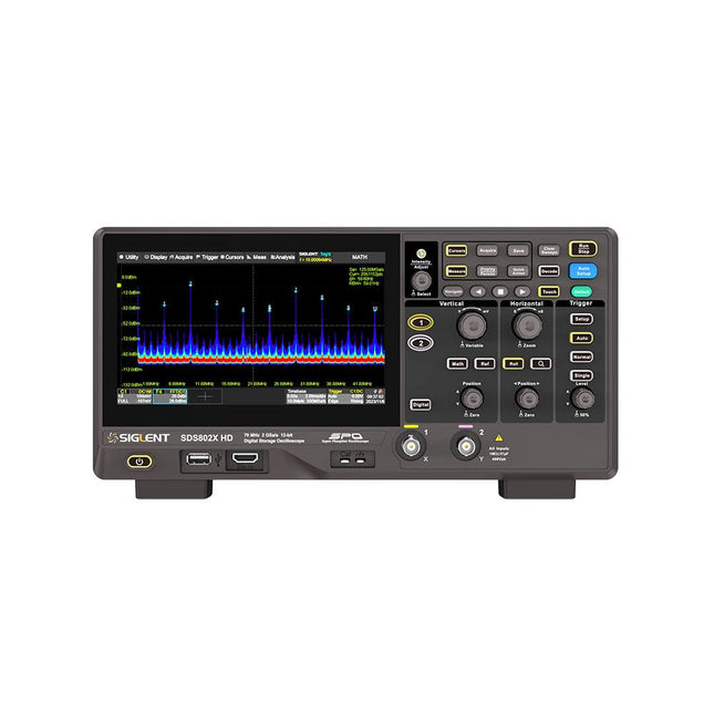
Siglent Siglent SDS822X HD 2-ch Oscilloscope (200 MHz)
The Siglent SDS822X HD digital storage oscilloscope is based on 2 GSa/s, 12-bit Analog-Digital Converters and front ends with excellent noise floor performance. With a 200 MHz bandwidth, and a maximum record length of 100 Mpts, and the capability to analyze 2 analog channels alongside 16 digital channels, the SDS822X HD is perfectly suited for mixed signal analysis. Features 12-bit High Resolution 12-bit Analog-Digital Convertors with sample rate up to 2 GSa/s Front ends with 70 μVrms noise floor @ 200 MHz bandwidth 2/4 analog channels, up to 700 MHz bandwidth SPO technology Waveform capture rate up to 120,000 wfm/s (normal mode), and 500,000 wfm/s (sequence mode) Supports 256-level intensity grading and color temperature display modes. Up to 50 Mpts record length Digital trigger system Intelligent trigger: Edge, Slope, Pulse width, Window, Runt, Interval, Dropout, Pattern, Video (HDTV supported), Qualified, Nth edge, Delay, Setup/Hold time. Serial bus triggering and decoder, supports protocols I²C, SPI, UART, CAN, LIN. Segmented acquisition (Sequence) mode, dividing the maximum record length into multiple segments (up to 80,000), according to trigger conditions set by the user, with a very small dead time between segments to capture the qualifying event. History waveform record (History) function, the maximum recorded waveform length is 80,000 frames. Automatic measurements on 50+ parameters, supports statistics with histogram, track, trend, Gating measurement, and measurements on Math, History and Ref. 4 Math traces (2 Mpts FFT, addition, subtraction, multiplication, division, integration, differential, square root, etc.), supports formula editor. Abundant data analysis functions such as Search, Navigate, Counter, Bode plot and Power Analysis High Speed hardware-based Mask Test function, with Mask Editor tool for creating user-defined masks 16 digital channels (optional) 25 MHz waveform generator (optional) 7" TFT-LCD display with 1024 x 600 resolution; Capacitive touch screen supports multi-touch gestures. Interfaces include: USB Hosts, USB Device (USBTMC), LAN (VXI-11/Telnet/Socket), Pass/Fail, Trigger Out Built-in web server supports remote control over the LAN port using a web browser. Supports SCPI remote control commands. Supports external mouse and keyboard. Supports NTP. Specifications Analog Channels 2 Bandwidth 200 MHz Vertical resolution 12-bit Sample rate (Max.) One channel mode: 100 Mpts/chTwo channel mode: Mpts/chFour channel mode: 25 Mpts/ch Memory depth (Max.) One channel mode: 50 Mpts/chTwo channel mode: 25 Mpts/ch Waveform capture rate (Max.) Normal mode: 120,000 wfm/sSequence mode: 500,000 wfm/s Trigger type Edge, Slope, Pulse width, Window, Runt, Interval, Dropout, Pattern, Video, Qualified, Nth edge, Delay, Setup/Hold time, Serial Serial trigger and decode (Standard) I²C, SPI, UART, CAN, LIN Measurement 50+ parameters, statistics, histogram, trend, and track supported Math 4 traces 2 Mpts FFT, Filter, +, -, x, ÷, ∫dt, d/dt, √, Identity, Negation, Absolute, Sign, ex, 10x, ln, lg, Interpolation, MaxHold, MinHold, ERES, Average. Supports formula editor Data analysis Search, Navigate, History, Mask Test, Counter, Bode plot, and Power Analysis Digital channel (optional) 16-channel; maximum sample rate up to 1 GSa/s; record length up to 10 Mpts USB AWG module (option) One channel, 25 MHz, sample rate of 125 MHz, wave length of 16 kpts, isolated output I/O 2x USB 2.0 Host, USB 2.0 Device, 10/100 M LAN, Auxiliary output (TRIG OUT, PASS/FAIL), SBUS (Siglent MSO) Probe (Standard) Passive probe PB470 for each channel Display 7 TFT-LCD with capacitive touch screen (1024x600) Included 1x Siglent SDS822X Oscilloscope 2x Passive probe (200 MHz) PP520 1x Power cord (EU) 1x USB cable 1x Certificate of calibration 1x Quick start Downloads Datasheet Manual Programming guide
€ 635,25
-
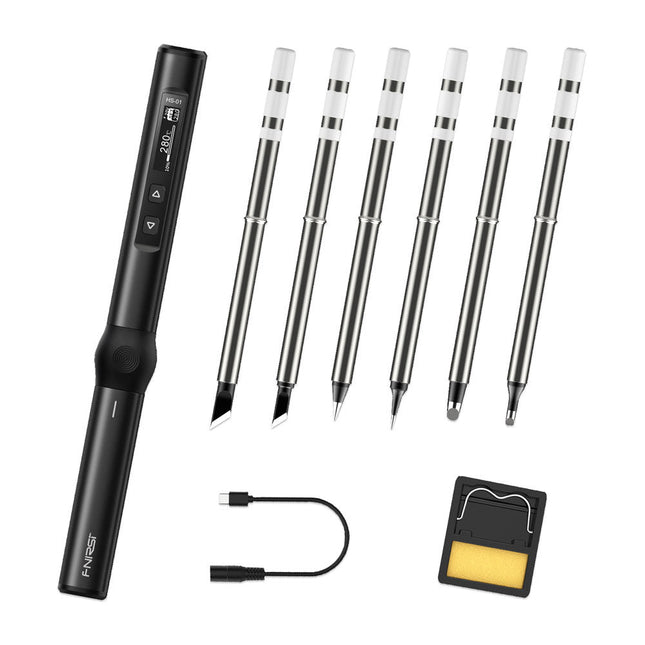
FNIRSI FNIRSI HS-01 Smart Soldering Iron (incl. 6 Soldering Tips)
The perfect tool for quick repairs The FNIRSI HS-01 is a powerful, adjustable smart soldering iron with a built-in 0.87-inch OLED display that quickly reaches temperatures between 80-420°C (180-780°F). The display shows all important information, including the status of the temperature level, the set temperature, the supply voltage and the power percentage. You can set the input voltage from 9-20 V directly in the menu according to your needs. The integrated sleep mode automatically turns off the iron after 30 minutes. Features 96 W input (DC) 65 W PD power OLED display Constant temperature & fast heating CNC metal integral molding Smart safety anti-scald Mini pocket size Ergonomic design Aluminum material Left/right hand switch Efficient heat radiation Inductive sleep Color: Black Specifications Power 65 W Screen 0.87" OLED Operating voltage 9-20 VDC Power supply USB-C Temperature range 80-420°C (180-780°F) Fast charging protocol PD trigger Dimensions 184 x 20 x 20 mm (7.24 x 0.79 x 0.79') Weight 56 g Power Selection Operating voltage 20 V 15 V 12 V 9 V Operating current ≥3.25 A ≥2.5 A ≥2 A ≥1.5 A Power 65 W 37.5 W 24 W 13.5 W Tin melting time 8s 12s 17s 30s Included 1x FNRISI HS-01 smart soldering iron 6x Soldering iron tips (HS01-BC2, HS01-KR, HS01-K65, HS01-B2, HS01-ILS, HS01-BC3) 1x DC to USB-C power cable 1x Mini soldering iron stand 1x Manual Required Power adapter USB-C cable Downloads Manual Firmware V0.3.s19
€ 82,00
-

OWON OWON ADS924A 4-ch Oscilloscope (250 MHz)
The OWON ADS900A series is a compact 12-bit digital oscilloscope offering up to 2 GSa/s, 100 Mpts memory, and 125/250 MHz bandwidth. With its 7" multi-touch display, FFT, protocol decoding, and integrated logic analyzer, it delivers precise signal analysis for lab, workshop, and field applications. Specifications ADS914A ADS924A Bandwidth (-3 dB) 125 MHz 250 MHz Channels 4 Max. sample rate 2 GSa/s (single-channel) 1 GSa/s (dual-channel) 500 MSa/s (full-channel) DC Gain Accuracy 3% (≤1 mV) 2% (≥2 mV) Max memory depth 100M Vertical resolution 12 bits Relay time accuracy ±25 ppm (typical) Input Impedance 1 MΩ±2%, parallel with20 pF±5 pF Probe Attenuation Coefficient 1.00μX-1M.00X,step by 1-2-5, support custom Trigger type Edge, Video, Pulse, Slope, Runt, Windows, Timeout, Nth, Logic, RS232/UART, I²C, SPI CAN, LIN Bus decoding RS232/UART, I²C, SPI, CAN, LIN Auto measurement Period, Frequency, +Width, -Width, Rise Time, Fall Time, Scr Duty, +Duty,-Duty, Vavg, Vpp, VRMS, Overshoot, Vmax, Vmin, Vtop, CycRms, Vbase, Vamp, Preshoot, Std Dev, +Pulse Cnt, -Pulse Cnt, Rise Cnt, Fall Cnt, Area, Cyc Area, Delay(A↑-B↑), Delay(A↑-B↓), Delay(A↓-B↑), Delay(A↓-B↓), Phase(A↑-B↑) Phase(A↑-B↓), Phase(A↓-B↑), Phase(A↓-B↓), FRR(A↑-B↑), FRF(A↑-B↓) FFR(A↓-B↑), FFF(A↓-B↓), LRR(A↑-B↑), LRF(A↑-B↓), LFR(A↓-B↑), LFF(A↓-B↓) Waveform Math +, -, *, /, &&, ||, ^, !, Intg, Diff, Sqrt, Function operation (Lg / Ln / Exp / Abs / Sine / Cosine / Tan), FFT, FFT rms, User Defined, digital filter (low pass, high pass, band pass, band reject) Frequency counter 6-digit frequency counter Maximum frequency: maximum analog bandwidth of oscilloscope Voltmeter Support DC, AC+DCrms, ACrms, Resolution: 4 digits (ACV/DCV) Logical Analyzer Specifications Number of channels 16 input channels (D0-D15) (D0 to D7, D8 to D15) Max. input voltage ±40V peak CAT I, transient overvoltage 800Vpk Input Impedance 100kΩ, 8 pF Vertical resolution 1 bit Other Communication Interface HDMI, USB device, USB Host, Trig Out (P/F), LAN Display 7 inch (1024x600), capacitive multi-touch screen Power supply interface USB-C Dimensions 260 x 160 x 78 mm Weight 1.5 kg Included 1x OWON ADS924A Oscilloscope 1x Power Adapter 1x Power Cord 1x USB Cable 1x Probe 1x Quick Guide Downloads Manual Quick Guide PC Software
€ 688,49
-
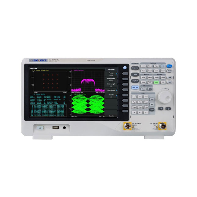
Siglent Siglent SSA3075X Plus Spectrum Analyzer (9 kHz – 7.5 GHz)
The Siglent SSA3075X Plus spectrum analyzer is a powerful and flexible tool for RF signal and network analysis. With a frequency range of 7.5 GHz, the analyzer delivers reliable automatic measurements and multiple modes of operation: spectrum analyzer the base, optional functions include RF power measurement, vector signal modulation analysis, reflection measurement, and EMI test. Applications include broadcast monitoring/evaluation, site surveying, S-parameter measurement, analog/digital modulation analysis, EMI pre-compliance test, research and development, education, production, and maintenance. Features Spectrum Analyzer Frequency Range from 9 kHz to 7.5 GHz –165 dBm/Hz Displayed Average Noise Level (Typ.) –98 dBc/Hz. @ 10 kHz Offset Phase Noise (1 GHz, Typ.) Level Measurement Uncertainty <0.7 dB (Typ.) 1 Hz Minimum Resolution Bandwidth (RBW) Preamplifier (Std.) Tracking Generator (incl. free of charge) Analog and Digital Signal Modulation Analysis Mode (opt.) Reflection Measurement Kit (opt.) EMI Filter and Quasi-Peak Detector Kit (opt.) Advanced Measurement Kit (opt.) 10.1-inch Multi-Touch Screen , Mouse and Keyboard supported Web Browser Remote Control on PC and Mobile Terminals and File Operation Specifications SSA3015X Plus SSA3021X Plus SSA3032X Plus SSA3075X Plus Frequency Range 9 kHz ~ 1.5 GHz 9 kHz ~ 2.1 GHz 9 kHz ~ 3.2 GHz 9 kHz ~ 7.5 GHz Resolution Bandwidth 1 Hz ~ 1 MHz 1 Hz ~ 1 MHz 1 Hz ~ 1 MHz 1 Hz ~ 3 MHz Phase Noise <–99 dBc/Hz <–98 dBc/Hz <–98 dBc/Hz <–98 dBc/Hz Total Amplitude Accuracy <1.2 dB <0.7 dB <0.7 dB <0.7 dB Display Average Noise Level –156 dBm/Hz –161 dBm/Hz –161 dBm/Hz –165 dBm/Hz Included Siglent SSA3075X Plus spectrum analyzer USB cable Power cord Quick start guide Downloads Datasheet Manual Documentation Firmware
€ 7.875,89
-
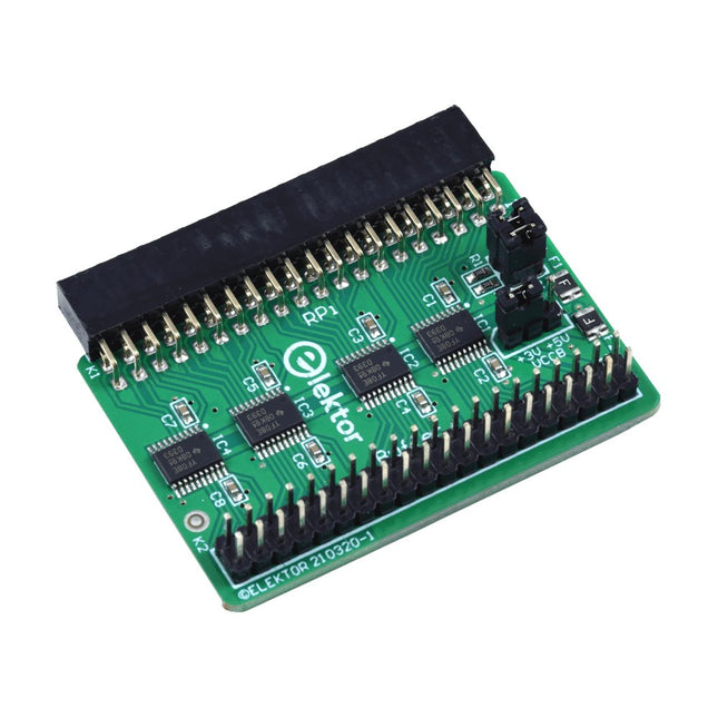
Elektor Labs Elektor Raspberry Pi Buffer Board
When you experiment with the Raspberry Pi on a regular basis and you connect a variety of external hardware to the GPIO port via the header you may well have caused some damage in the past. The Elektor Raspberry Pi Buffer Board is there to prevent this! The board is compatible with Raspberry Pi Zero, Zero 2 (W), 3, 4, 5, 400 and 500. All 26 GPIOs are buffered with bi-directional voltage translators to protect the Raspberry Pi when experimenting with new circuits. The PCB is intended to be inserted in the back of Raspberry Pi 400/500. The connector to connect to the Raspberry Pi is a right angled 40-way receptacle (2x20). The PCB is only a fraction wider. A 40-way flat cable with appropriate 2x20 headers can be connected to the buffer output header to experiment for instance with a circuit on a breadboard or PCB. The circuit uses 4x TXS0108E ICs by Texas Instruments. The PCB can also be put upright on a Raspberry Pi. Downloads Schematics Layout
€ 34,95
Members: € 31,46


