
Search results for "motor OR control OR development OR bundle"
-

Elektor Digital Elektor Mars/Avril 2025 (PDF) FR
Le téléchargement intégral de ce numéro est disponible pour nos membres GOLD et GREEN sur le site Elektor Magazine ! Pas encore membre ? Cliquez ici. L'architecture de processeur open-source RISC-V16 cartes et MCU à connaître un lecteur audio avec égaliseur basé sur un FPGAMixage audio numérique avec un Arduino MKR Vidor 4000 tête laser pour l’horloge de sable basé sur Raspberry Pi PicoDessiner avec la lumière participez au concours STM32 Edge AI système de contrôle environnemental multi-capteurs pour les plantesMesure sans fil de l'approvisionnement en eau et de la luminosité porte automatique contrôlée par l'IA et MaixduinoReconnaissance faciale avec une caméra l’électronique embarquée en 2024L’IA va redéfinir l’industrie Calcul en mémoire basé sur la charge chez EnCharge AI des opérations d'IA avec 10 fois moins d'énergie et des coûts divisés par 20 Une carte pour le développement et l’entraînement des modèles ML d’analyse des vibrations Elektor Mini-WheelieKit robot gyropode (robot autostabilisé) MCUViewerMCUViewer outil de débogage open source multiplateforme isolateur USB 2.0Isolation éléctrique pour les périphériques USB anticipation et actionApplication pratique de la maintenance prédictive SPoE – compatibilité électromagnétiquePaire unique avec Power-over-Ethernet à travers les yeux d'EMC rétro-techCréer un monde nouveau avec la télévision couleur surveillance ECGavec des modules Hexabitz et STM32CubeMonitor la bataille pour l’IA en périphérie HaLow atteint une distance Wifi record de 16 km à 900 MHz première puce embarquée CHERI RISC-V et programme d'accès anticipé la détection des incendies de forêt de troisième génération utilise des liaisons satellites sur le vifDélices et supplices du choix démarrer en électronique......Filtrage et contrôle de la tonalité Kit d'horloge quasi-analogiqueNouvelle version d'un classique d'Elektor une approche modulaire de test des capteursCarte de test de capteurs basée sur l'ESP32-S3 2025 : une odyssée de l'IAL'essor des modèles de fondation et leur impact sur l'accessibilité de l'IA Synthétiseur MIDI autonome Raspberry Pi (1)Préparation d'une plateforme pour des expériences d’IA en périphérie projet 2.0Corrections, mises à jour et courrier des lecteurs Le RISC-V AI, un processeur à tout faire : CPU, GPU, DSP, FPGA paroles de PDG : fraîcheur, silence et finesse programmation Dual-Core avec le Raspberry Pi PicoLe monde de la programmation parallèle
€ 10,95
-

FNIRSI FNIRSI SG-003A Signal Generator
The FNIRSI SG-003A multi-functional Signal Generator a.k.a. Process Meter/Calibrator is a high-precision voltage/current generator and meter. The SG-003A provides highly accurate reference voltages or currents for testing and calibrating other measurement instruments like multimeters and oscilloscopes. Besides voltages and currents, the SG-003A also generates rectangular pulse signals with precisely programmable frequencies and duty cycles. Its converter mode turns the SG-003A into a precision voltage-controlled current source, or current-controlled voltage source, and even a voltage- or current-controlled frequency generator. The SG-003A is a great tool for checking your multimeter’s accuracy and precision, and for testing e.g. LEDs. Features Accuracy (voltage/current) 0.1% ±0.005 Resolution (current) 0.01 mA Frequency 0-10 kHz Resolution 5 digits Output power 24 V Display 2.4" TFT LCD (320 x 240) Dimensions 92 x 72 x 30 mm Weight 165 g Specifications Signal Range Precision Resolution Max load External power supply Active current output 0~24 mA ±(0.1% + 0.005) 0.01 mA 750 Ω Passive current output (XMT) 0~24 mA ±(0.1% + 0.005) 0.01 mA 0~30 V Voltage output 0~24 V ±(0.1% + 0.005) 0.01 V 24 V loop 0~24 mA ±(0.1% + 0.005) 0.01 mA Frequency output 0~9999 Hz ±2% 5 digits Current input 0~24 mA ±(0.1% + 0.005) 0.01 mA Voltage input 0~30 V ±(0.1% + 0.005) 0.01 V Included 1x FNIRSI SG-003A Signal generator 4x Test clips 1x USB charger 1x USB-C cable 1x Manual Downloads Manual Firmware V4.3
€ 69,95
-

Elektor Digital Elektor Septembre/Octobre 2021 (PDF)
VOYAGE DANS LES RÉSEAUX NEURONAUX (1ÈRE PARTIE)Les neurones artificiels TEST DE PRÉCONFORMITÉ CEM POUR UN PROJET ALIMENTÉ EN COURANT CONTINUPartie 1 : RSIL double continu CHARGE ÉLECTRONIQUE EN CC ET CAJusqu?à 400 V et 10 A (crête) DÉMARRER EN ÉLECTRONIQUE (9)N'ayez pas peur du choc... un peu de « self control » suffit ! TRAITEMENT D'IMAGES AVEC LE MODULE JETSON NANO DE NVIDIA (1ÈRE PARTIE)Matériel et logiciel ZOOM SUR LES TRANSFORMATEURS SECTEURComportement transitoire à l?allumage et l?extinction « YES WE CAN » AVEC PICAN 3Module de bus CAN pour le Raspberry Pi 4 CENTRALE SOLAIRE SUR BALCONUn investissement vite amorti PRISE DE VUE ET DIFFUSION VIDÉO EN CONTINU AVEC UN RASPBERRY PI 4La caméra Raspberry Pi HQ en action UTILISATION D?ÉCRANS DANS LES PROJETS RASPBERRY PIExtrait : écrans à diodes électroluminescentes organiques (OLED) PROPELLER 2 DE PARALLAX (4)Envoi de chaînes de caractères 60 ANS D?ELEKTORRegard sur septembre DANS L?ANTRE DE?Menno van der Veen et de ses tubes amplificateurs CIRCUITS HYBRIDES ROSE DES VENTS AVEC LE CAPTEUR GY-271Ou pourquoi il faut faire des huit pour calibrer un capteur MESUREZ VOTRE EMPREINTEÉlectronique et émissions de gaz à effet de serre THERMOSTAT CONNECTÉ À ESP32Conservez votre vin à la bonne température ! LÉVITATION MAGNÉTIQUE, VERSION NUMÉRIQUEComparateur analogique remplacé par un ESP32 Pico ULTIMATE ARDUINO UNO HARDWARE MANUAL - FR TRANSLATIONExtrait : chargeur d?amorçage du microcontrôleur principal MICROPYTHON POUR L'ESP32 ET SES COPAINSPartie 2 : piloter facilement les écrans matriciels CARTE MADMACHINE SWIFTIOUn langage récent pour du matériel tout nouveau SUR LE VIFPassions incertaines HEXADOKUCasse-tête pour elektorniciens
€ 10,95
-

Elektor Circuit Special 2026 (FR)
Le téléchargement intégral de ce numéro est disponible pour nos membres GOLD et GREEN sur le site Elektor Magazine ! Pas encore membre ? Cliquez ici. source de courant pour tester les diodes ZTest des diodes Z de 1 à 54 V sous 1 à 50 mA testeur de bracelet antistatiqueUn testeur de référence à trois états : réussite, limite ou échec testeur de réponse transitoire pour alimentationGénérateur d'échelon de charge répétable pour alimentations de labo séquenceur euclidien sans microcontrôleurMotifs de déclenchement et séquences CV avec une simple logique CMOS lampe clignotante à LED pour portails avec alerte sonore Besoin de circuits imprimés ? Le service PCB d'Elektor est fait pour vous. minuterie pour brosse à dentsAvec un petit PIC verrou combiné magnétique sans contactAvec le capteur de position angulaire AS5600 préampli à faible bruit sur pilePour micros dynamiques Arduino Nano TestLabMesure, contrôle et régulation effet lumineux au rythme des bassesAccentuez le rythme musical filtre coupe-basAucun risque d'effet larsen dans votre système audio générateur précis d’ondes carrées à 1 Hz pour plaque d’essaiA Reliable CMOS-Based Clock Source 555 à l’enversRapports cycliques jusqu’à zéro Du Halfgeleidergids aux Circuit Specials65 ans d'innovation en électronique isolation électriqueInterface CAN avec isolateur numérique et module d’alimentation isolé spongillatorUn oscillateur à éponge True Random Number GeneratorAvec test du khi carré intégré visionneuse 3D pour pages HTMLSimple, et presque sans programmation programmation avec TLScriptUn langage de script pour la mesure, les tests et le contrôle conception de circuits : conseils d'experts rétroactionqu'est-ce que c'est et pourquoi est-ce important ? une carte, des idées infinies : Arduino UNO QDu jeu rétro à la surveillance environnementale en temps réel réparation d'une antenne « donut » Standby KillerUn vrai interrupteur marche/arrêt pour votre téléviseur test d'accusMesurer les capacités de batteries avec l'Arduino Nano alimentation pour ampli audio de puissanceSans bruit secteur cartes de prototypage RFMontages rapides avec des cartes de prototypage pour RF protection contre les surtensions T3Un parafoudre de type 3 pour vos équipements sensibles thermostat d'ambiance IdO Avec le module MCU Xiao basé sur ESP32-C3/S3 du rigide au smartÉlectronique flexible et imprimée : entre vision et réalité industrielle
€ 15,50
-

OWON OWON HDS272S 2-ch Oscilloscope (70 MHz) + Multimeter + Signal Generator
Oscilloscope, multimeter and waveform generator in the same battery-powered device, to work on the go. Features Oscilloscope + multimeter + waveform generator, multifunction in one 3.5-inch high-resolution, high-contrast colour LCD display, suitable for outdoor use 18650 lithium battery, comprehensive power consumption ≤3 W, can work continuously for about 6 hours USB-C interface, support power bank, support PC software connection Self-calibration function SCPI supported, facilitate secondary development Specifications Oscilloscope Bandwidth 70 MHz Channels 2-ch Oscilloscope + 1-ch Generator Sample Rate 250 MSa/s Acquisition Model Normal, Peak detect Record Length 8K Display 3.5-inch LCD Waveform Refresh Rate 10,000 wfrms/s Input Coupling DC, AC, and Ground Input Impedance 1 MΩ ±2%, in parallel with 16pF±10pF Probe Attenuation Factors 1X,10X,100X,1000X,10000X Max. input Voltage 400 V (DC+AC, PK-PK, 1MΩ input impedance) (10:1 probe attenuation) Bandwidth Limit (typical) 20 MHz Horizontal Scale 5 ns/div - 1000 s/div, step by 1 - 2 - 5 Vertical Sensitivity 10 mV/div - 10 V/div Vertical Resolution 8 bits Trigger Type Edge Trigger Modes Auto, Normal, single Automatic Measurement Period, Frequency, Mean, PK-PK, Max, Min Cursor Measurement ΔV, ΔT, ΔT& ΔV between cursors Communication Interface USB Type-C Multimeter Max. Resolution 20,000 counts Testing Mode Voltage, Current, Resistance, Capacitance, Diode, and Continuity test Input Impedance 10 MΩ Max Input Voltage AC: 750 V | DC: 1000 V Max Input Current DC: 10 A | AC: 10 A Diode 0-2 V Waveform Generator Frequency Output Sine 0.1 Hz - 25 MHz Square 0.1 Hz - 5 MHz Ramp 0.1 Hz - 1 MHz Pulse 0.1 Hz - 5 MHz Arbitrary 0.1 Hz - 5 MHz Sampling Rate 125 MSa/s Channel 1-ch Amplitude Range 20 mVpp - 5 Vpp Waveform Length 8K Vertical Resolution 14 bits Output Impedance 50Ω Downloads User Manual for HDS200 Series SCPI Protocol for HDS200 Series Quick Guide for HDS200 Series PC Software for OWON HDS200 Series
€ 199,65
-
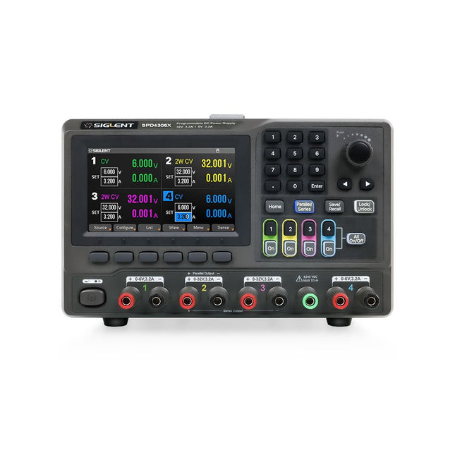
Siglent Siglent SPD4306X 4-ch DC Power Supply (400 W)
The Siglent SPD4306X is a 4-channel DC Linear Programmable Power Supply equipped with a 4.3-inch TFT-LCD display, friendly human-machine interface, and excellent performance indicators. Real-time waveform display provides engineers with an informative user interface. SPD4306X offers a total output power of 400 W with a resolution of 1 mV/1 mA. The maximum voltage and current for each channel are as follows: CH1: 15 V/1.5 A CH2: 30 V/6 A CH3: 30 V/6 A CH4: 15 V/1 A Features Rated output power: 400 W Rated voltage: 32 V, 12 V, 30 V Up to four high-precision power supplies with independent controllable outputs, supporting CH2 and CH3 series and parallel connections Clear graphical interface with waveform and timer display modes 5-digit voltage and current display with minimum resolution of 1 mV, 1 mA Fast output response time: <50us The high current channel support remote voltage compensation sense function. The maximum compensation voltage is 0.6 V Overvoltage protection and overcurrent protection or safe and accurate operation Equipped with a 4.3-inch TFT-LCD display (480 x 272 resolution) USB and LAN standard communication USB-GPIB module is optional Excellent channel density with up to 4 channels in a 3U half rack package Internal data storage for setups and parameters Embedded Web Server with instrument communication that doesn’t require software installation Fully SCPI programming command set support as well as a LabView driver for remote control and system automation Specifications SPD4323X SPD4121X SPD4306X Channel Output CH1: Voltage 0 to 6 V Current 0 to 3.2 ACH2: Voltage 0 to 32 V Current 0 to 3.2 ACH3: Voltage 0 to 32 V Current 0 to 3.2 ACH4: Voltage 0 to 6 V Current 0 to 3.2 A CH1: Voltage 0 to 15 V Current 0 to 1.5 ACH2: Voltage 0 to 12 V Current 0 to 10 ACH3: Voltage 0 to 12 V Current 0 to 10 ACH4: Voltage 0 to 15 V Current 0 to 1.5 A CH1: Voltage 0 to 15 V Current 0 to 1.5 ACH2: Voltage 0 to 30 V Current 0 to 6 ACH3: Voltage 0 to 30 V Current 0 to 6 ACH4: Voltage 0 to 15 V Current 0 to 1 A Resolution 1 mV, 1 mA 1 mV, 1 mA 1 mV, 1 mA Setting Accuracy Voltage: ±(0.03% of reading+10) mV, Current: ±(0.3% of reading+10) mA Voltage: ±(0.03% of reading+10) mV, Current: ±(0.3% of reading+10) mA Voltage: ±(0.03% of reading+10) mV, Current: ±(0.3% of reading+10) mA Readback Accuracy Voltage: ±(0.03% of reading+10) mV, Current: ±(0.3% of reading+10) mA Voltage: ±(0.03% of reading+10) mV, Current: ±(0.3% of reading+10) mA Voltage: ±(0.03% of reading+10) mV, Current: ±(0.3% of reading+10) mA Display 4.3" TFT-LCD 5-digit voltage and current display 4.3" TFT-LCD 5-digit voltage and current display 4.3" TFT-LCD 5-digit voltage and current display Output power 240 W 285 W 400 W Included 1x Siglent SPD4306X Power Supply 1x Power cord (EU) 1x Output test cord (3 A) 1x USB cable 1x Quick start guide Downloads Datasheet Manual Quick start
€ 1.101,10
-
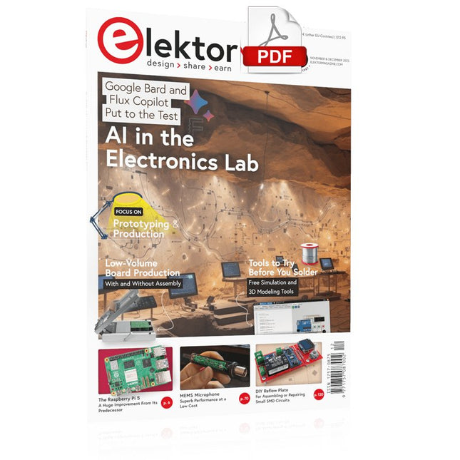
Elektor Digital Elektor November/December 2023 (PDF)
Elektor GREEN and GOLD members can download their digital edition here. Not a member yet? Click here. The Raspberry Pi 5A Huge Improvement From Its Predecessor AI in the Electronics LabGoogle Bard and Flux Copilot Put to the Test Arduino Nano Waveform GeneratorNano + Code = Function Generator Solar-Powered Christmas GarlandAn Eco-Friendly Solution for Garnishing Your Balcony USB Killer DetectorBetter Safe Than Sorry A Simple CNCed EnclosureWith Autodesk Fusion 360 for Personal Use Low-Volume Board ProductionWith and without Assembly IoT Simulation Simplified with WokwiDeveloper Uri Shaked on Design, Software, and More A Bare-Metal Programming Guide (Part 3)CMSIS Headers, Automatic Testing, and a Web Server LoRa, a Swiss Army Knife (2)The Hardware and Software MEMS Microphone Design and Construction Tools to Try Before You SolderSimulation and 3D Modeling Tools That Can Be Used for Free New Tools From Microchip!PICkit 5 and MPLAB ICD 5 Available Now! Rapid Prototyping of Flexible, Stretchable ElectronicsHow the Voltera NOVA Speeds Up Innovation in Wearable Electronic Systems Galvanic IsolationUsing Phototransistor Optocouplers Successfully The Complex Solution or the Anybus Solution?Embedded Industrial Ethernet in 2 Days Rather Than Many Months Your Essential DFM ChecklistHow to Start Designing for Manufacture 3D Printing FilamentsTypes, Features and Use in Prototyping Specialists for Effective Signal Analysis from ELF to EHF BandAaronia’s latest real-time SPECTRAN® V6 series spectrum analyzers Challenges of DFM Analysis for Flex and Rigid-Flex Design Setting Up an SMT Line The Right Combination for a Reliable Assembly Revolutionizing IndustriesThe Rise of Autonomous Mobile Robots (AMRs) Evolved for More ChallengesRohde & Schwarz Adds Eight-Channel R&S MXO 5 to Next-Generation Oscilloscopes Starting Out in Electronics……Amplifying Differences Mini Reflow PlateFor Assembling or Repairing Small SMD Circuits Don’t Start with a Prototype – Start with a Pretotype!Check That a Market Exists for Your Product Before Warming Your Soldering Iron 2023: An AI OdysseyGetting Help Designing a Physical Project Brussels Is InnovatingSupport for Deep Tech
€ 7,50
-

Elektor Publishing Getting Started With Java Using Eclipse
Mastering the Language and the Development Platform Many people would like to learn Java but getting started is not easy since programming with Java requires at least two things: mastering the programming language and the development environment. With the help of many examples, this book shows how the language is structured. In addition, it employs the Eclipse development environment as an example of a powerful tool to teach developing Java programs. In Basics, the first part of the book, you acquire your Java and Eclipse basic knowledge. This part lays the programming foundations, gives you an overview of Java technology, and shows you what is special about object-oriented programming. In the second part called Java Language, everything revolves around the subtleties of the Java language and this is where the first small Java applications are created, aided by a fine blend of the knowledge part and practical exercises. Java Technology is both the name and the focus of the third part which also introduces you to the rules to observe when programming, what class libraries are and what advantages they have. In addition, you will learn how to test programs, what algorithms are, and how to program them. The fourth part, Java Projects, enables you to apply all the previous elements in an application with a graphical user interface. The project shows how to develop a larger application piece by piece with the Eclipse development environment. The Appendix concludes with a section on frequent errors that can occur when working with Eclipse, and a Glossary.
€ 44,95
Members: € 40,46
-
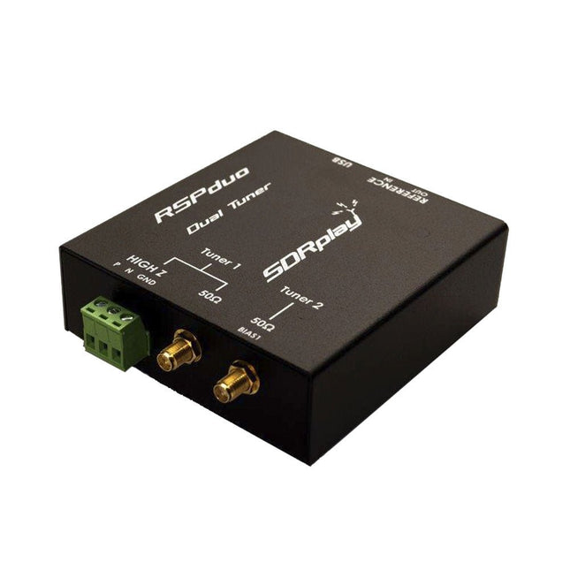
SDRplay SDRplay RSPduo Dual-Tuner 14-bit SDR Receiver (1 kHz to 2 GHz)
The SDRplay RSPduo is a high performance dual-tuner 14-bit SDR receiver. Housed in a high quality steel enclosure, each tuner can operate individually anywhere between 1 kHz and 2 GHz with up to 10 MHz of bandwidth or both tuners can operate simultaneously anywhere between 1 kHz and 2 GHz with up to 2 MHz of bandwidth per tuner. A high stability reference along with external clocking features makes this device ideally suited to industrial, scientific & educational applications. Features Dual tuner provides independent coverage from 1 kHz to 2 GHz using 2 antenna ports simultaneously 14-bit ADC silicon technology Up to 10 MHz visible bandwidth (single tuner mode) or 2 slices of 2 MHz spectrum (dual tuner mode) 3 software-selectable antenna ports (2x 50Ω and 1x 1kΩ high impedance balanced/unbalanced input) High impedance antenna port (1 kHz to 30 MHz) with selectable MW notch filter and choice of 2 pre-selection filters Software selectable AM/FM and DAB broadcast band notch filters for the 2 SMA antenna (1 kHz to 2 GHz) antenna ports External clock input and output enables easy synchronisation to multiple RSPs or external reference clock Powers over the USB cable with a simple type B socket 11 high-selectivity, built in front-end preselection filters on both the 2 SMA antenna ports Software selectable multi-level Low Noise Preamplifier Bias-T power supply for powering antenna-mounted LNA Enclosed in a rugged black painted steel case. SDRuno – World Class SDR software for Windows Documented API for new apps development Specifications Frequency Range 1 kHz – 2 GHz Antenna Connector SMA Antenna Impedance 50 Ohms Current Consumption (Typical) Single Tuner Mode: 180 mA (excl. Bias-T)Dual Tuner Mode: 280 mA (excl. Bias-T) USB Connector USB-B Maximum Input Power +0 dBm Continuous+10 dBm Short Duration ADC Sample Rates 2-10.66 MSPS ADC Number of Bits 14 bit 2-6.048 MSPS12 bit 6.048-8.064 MSPS10 bit 8.064-9.216 MSPS8 bit >9.216 MSPS Bias-T 4.7 V100 mA guaranteed Reference High Temperature Stability (0.5ppm) 24 MHz TCXO.Frequency error trimmable to 0.01ppm in field. Operating Temperature Range −10˚C to +60˚C Dimensions 98 x 94 x 33 mm Weight 315 g Downloads Datasheet Detailed Technical Information Software RSPdx-R2 vs RSPduo RSPdx-R2 RSPduo Continuous coverage from 1 kHz to 2 GHz ✓ ✓ Up to 10 MHz visible bandwidth ✓ ✓ 14-bit ADC silicon technology plus multiple high-performance input filters ✓ ✓ Software selectable AM/FM & DAB broadcast band notch filters ✓ ✓ 4.7 V Bias-T for powering external remote antenna amplifier ✓ ✓ Powers over the USB cable with a simple type B socket ✓ ✓ 50Ω SMA antenna input(s) for 1 kHz to 2 GHz operation (software selectable) 2 2 Additional software selectable Hi-Z input for up to 30 Mhz operation ✓ Additional software selectable 50Ω BNC input for up to 200 MHz operation ✓ Additional LF/VLF filter for below 500 kHz ✓ 24 MHz reference clock input (+ output on RSPduo) ✓ ✓ Dual tuners enabling reception on 2 totally independent 2 MHz ranges ✓ Dual tuners enabling diversity reception using SDRuno ✓ Rugged black painted steel case ✓ ✓ Overall performance below 2 MHz for MW and LF ++ + Multiple simultaneous applications + ++ Performance in challenging fading conditions (*using diversity tuning) + *++
€ 287,98
-
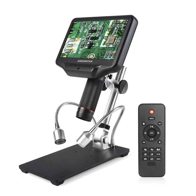
Andonstar Andonstar AD407 7" HDMI Digital Microscope
Examine your circuits with high precision and solder even the smallest SMDs and elements without any hassle. Features Multifunctional HDMI Digital Microscope features Full HD, comfortable headroom, improved ergonomy, multiple output signals with different resolutions. Tilt angle of the wide LCD monitor is adjustable. Comes with remote control. Can be used as stand-alone. Specifications Screen size 7 inch (17.8 cm) Image sensor 4 MP Video output UHD 2880x2160 (24fps)FHD 1920x1080 (60fps/30fps)HD 1280x720 (120fps) Video format MP4 Magnification Up to 270 times (27 inch HDMI monitor) Photo resolution Max. 12 MP (4032x3024) Photo format JPG Focus range Min. 5 cm Frame rate Max. 120fps (under 600 Lux Brightness & HDP120) Video interface HDMI Storage microSD card (up to 32 GB) Power source 5 V DC Light source 2 LEDs with the stand Stand size 20 x 12 x 19 cm Included 1x Andonstar AD407 Digital Microscope 1x Metal stand with 2 LEDs 1x Optical bracket 1x UV filter 1x IR remote 1x Switch cable 1x Power adapter 1x HDMI cable 2x Screws 1x Screwdriver 1x User manual Downloads Manual Model Comparison AD407 AD407 Pro AD409 AD409 Pro-ES Screen size 7 inch (17.8 cm) 7 inch (17.8 cm) 10.1 inch (25.7 cm) 10.1 inch (25.7 cm) Image sensor 4 MP 4 MP 4 MP 4 MP Video output 2160p 2160p 2160p 2160p Interfaces HDMI HDMI USB, HDMI, WiFi USB, HDMI, WiFi Video format MP4 MP4 MP4 MP4 Magnification Up to 270x Up to 270x Up to 300x Up to 300x Photo resolution Max. 4032x3024 Max. 4032x3024 Max. 4032x3024 Max. 4032x3024 Photo format JPG JPG JPG JPG Focus distance Min. 5 cm Min. 5 cm Min. 5 cm Min. 5 cm Frame rate Max. 120f/s Max. 120f/s Max. 120f/s Max. 120f/s Storage microSD card microSD card microSD card microSD card PC support No No Windows Windows Mobile connection No No WiFi + Measurement WiFi + Measurement Power source 5 V DC 5 V DC 5 V DC 5 V DC Light source 2 LEDs with the stand 2 LEDs with the stand 2 LEDs with the stand 2 LEDs with the stand Endoscope No No No Yes Stand size 20 x 12 x 19 cm 20 x 18 x 32 cm 18 x 20 x 30 cm 18 x 20 x 32 cm Weight 1.6 kg 2.1 kg 2.2 kg 2.5 kg
€ 185,13
-
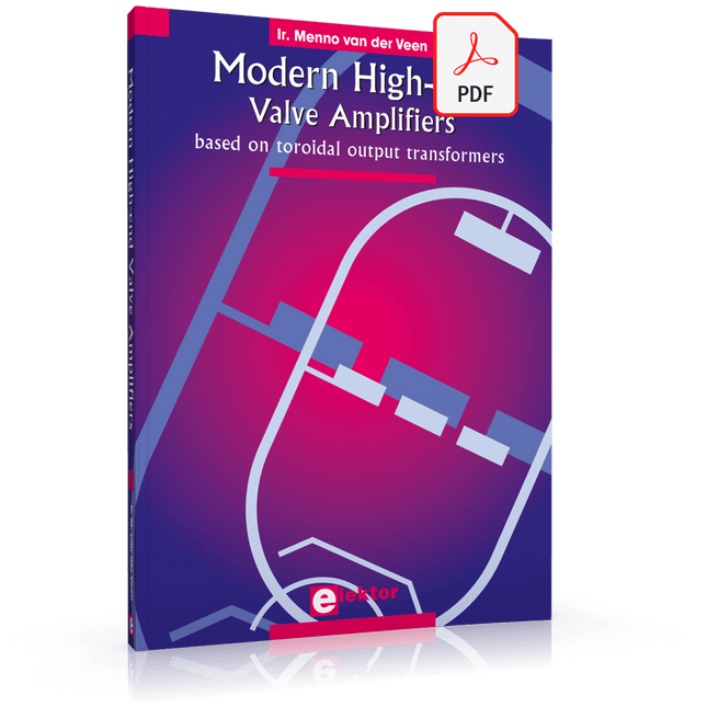
Elektor Digital Modern High-End Valve Amplifiers (E-book)
Valve Amplifiers are regarded by many to be the ne plus ultra when it comes to processing audio signals. The combination of classical technology and modern components has resulted in a revival of the valve amplifier. The use of toraidal-core output transformers, developed by the author over the past 15 years, has contributed to this revival. The most remarkable features of these transformers are their extremely wide frequency ranges and their very low levels of linear and nonlinear distortion. This book explains the whys and wherefores of toroidal output transformers at various technical levels, starting with elementary concepts and culminating in complete mathematical descriptions. In all of this, the interactions of the output valves, transformer and loudspeaker form the central theme. Next come the practical aspects. The schematic diagram of a valve amplifier often appears to be very simple at first glance, but anyone who has built a modern valve amplifier knows that a lot of critical details are hidden behind this apparent simplicity. These are discussed extensively, in connection with designs for amplifiers with output powers ranging from 10 to 100 watts. Finally, the author gives some attention to a number of special valve amplifiers, and to the theory and practice of negative feedback. In summary, this book offers innovative solutions for achieving perfect audio quality. Do-it-yourself builders, as well as persons who want to gain a deeper technical understanding of the complex world of audio transformers, valve amplifiers and audio signal processing, will find this book a rich and useful source of information.
€ 34,95
Members: € 31,46
-

Raspberry Pi Foundation FPC Camera Cable for Raspberry Pi 5 (500 mm)
Raspberry Pi 5 provides two four-lane MIPI connectors, each of which can support either a camera or a display. These connectors use the same 22-way, 0.5 mm-pitch “mini” FPC format as the Compute Module Development Kit, and require adapter cables to connect to the 15-way, 1 mm-pitch “standard” format connectors on current Raspbery Pi camera and display products.These mini-to-standard adapter cables for cameras and displays (note that a camera cable should not be used with a display, and vice versa) are available in 200 mm, 300 mm and 500 mm lengths.
€ 3,95€ 1,95Best Price


