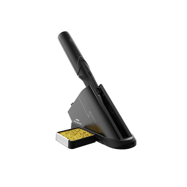
The Miniware Cordless Soldering Station TS1C (with integrated OLED screen and Bluetooth) is an intelligent soldering tool that heats up to 400°C in less than 20 seconds. Thanks to the built-in battery, the wireless soldering pen sits comfortably in the hand and is easy to use.
Features
New high-efficiency supercapacitor energy storage technology, 10,000-level charge and discharge times
Seperate design + true wireless, enjoy wireless soldering experience
BLE4.2 Bluetooth communication technology to realize remote control and setting
Standard PD2 20 V 45 W max power input, up to 36 W soldering power, can continuously solder more than 180 solder joints (0805) with a single full charge
Control station preheating to improve heating efficiency
3 expansion slots for accessories
Control Station
Standard PD2 20 V 45 W max power input, over current safety protection
128x64 pixel OLED screen, display soldering pen status in real time
Control station preheating, improve heating efficiency
Remote control and setting: temperature regulating, menu setting, viewing device info and status, etc.
Work as soldering stand and charging station
3 expansion slots for multiple expandable accessories like sponge slot
Soldering Pen
Built-in 750F high-efficiency energy storage supercapacitor, can be charged via control station (or via its USB Type-C interface in emergency cases)
36 W maximum heating power, can solder more than 180 solder joints (0805) continuously under a single full charge
Compatible with Miniware 3.5 mm audio interface soldering tips (TS80/80P soldering tip series)
Boost mode (holding the button on the pen)
Included
TS1C Soldering pen
TS1C Control station
Soldering tip (TS-B02)
Silicone cable
Sponge slot incl. sponge
Manual
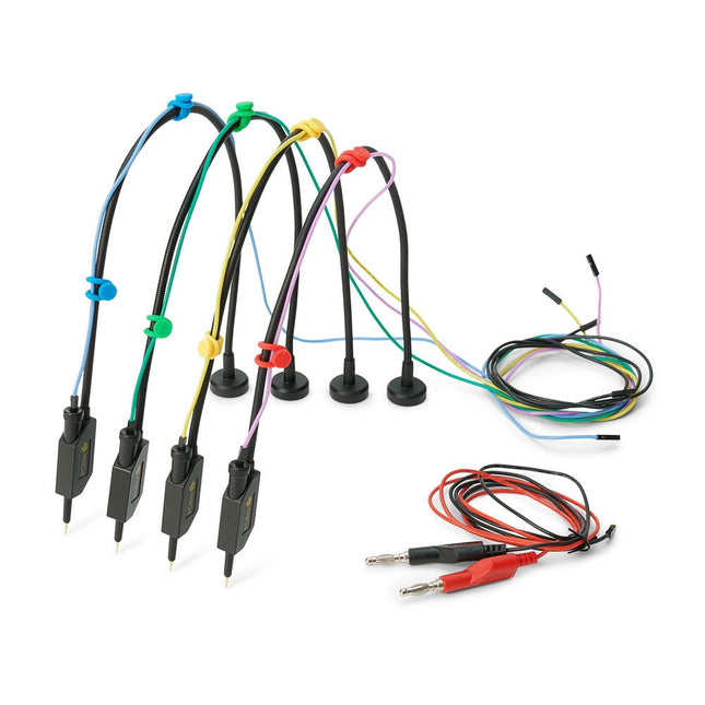
The SQ series of handsfree PCBite probes from Sensepeek are insulated, come with included color-coded cable holders and have a lower point of gravity making them even more stable compared with the original SP series of probes. All the loved features of handsfree measurement, exchangeable fine pitch spring tipped test needle and the minimalistic design is maintained to make traditional sized and handheld probes obsolete.
Features
All handsfree probes from Sensepeek makes instant measurements or long triggering sessions a breeze.
No more soldering wires to connect your probe or complicated tools to setup, just positioning the probe needle on any test point or component in the signal path and release.
Saves time and frustration during development, verification and repairs.
The minimalist design and the spring-loaded test needle makes it possible to simultaneously measure on fine pitch components and nearby signals.
Both length and weight of the SQ probes are perfectly balanced to be used with PCBite PCB holders and base plate which is a must for handsfree function.
The probe holder comes with a powerful magnet in the base, as for all PCBite probes and holders which makes the probe easy to place and reposition.
The SQ series of probes can be used handheld without the probe holder as they have an insulated grip but their full potential is used when measuring handsfree.
Included
4x SQ10 probes and pin tipped test needles (black)
2x Banana to dupont test wires (red/black)
5x Dupont to dupont test wires
1x Set of cable holders (4 colors)
4x Extra test needles
Downloads
User guide
The OWON SDS1102 is an affordable benchtop digital oscilloscope that combines solid performance with essential measurement features. This 2-channel oscilloscope offers a 100 MHz bandwidth, a 1 GS/s sampling rate, a 7-inch LCD display, and a 10 kpts memory depth, making it a practical choice for everyday electronics testing, troubleshooting, and education.
The SDS1102 features a simplified trigger system with level and edge triggering, making it easy to capture and analyze common signals. It is designed for applications that do not require deep memory or advanced trigger functions, offering a straightforward and cost-effective solution for basic signal analysis.
Features
Bandwidth: 100 MHz
2 channels
Sample rate: 1 GS/s
Ultra-thin body
7-inch high-res LCD
SCPI and LabVIEW supported
Specifications
Bandwidth
100 MHz
Horizontal Scale (s/div)
5 ns/div – 1000 s/div
Channel
2
Vertical Sensitivity
5 mV/div – 5 V/div (at input)
DC Gain Accuracy
3%
Vertical Resolution (A/D)
8 bits (2 channels simultaneously)
Input
Input Impedance
1 MΩ, 10 pF
Input Coupling
AC, DC, GND
Max Input Voltage
±400 V, CATI, CATII
Passive probes
х1; х10
Probe Attenuation Factor
х1; х10; х100; х1000
Trigger System
Trigger Mode
Auto, Normal, Single
Trigger Type
Edge, Video
Edge Trigger Source
CH1, CH2
Video Trigger
Sampling Type
Real-time
Sample Rate
1 GS/s
Equivalent Sample Rate
No
Wavelength
10K pts
Interpolation
sin(x)/x
Measurement and Mathematical Treatment System
Automatic Measurement
Vpp, Vavg, RMS, Frequency, Period, Vmax, Vmin, Vtop, Vbase, Width, Overshoot, Pre-shootRise time, Fall time, +Width, -Width, +Duty, -Duty, Delay A→B, Delay A→B, area, cycle area
Math Functions
Addition, Subtraction, Multiplication, Division, FFT
General Characteristics
Display type
7" color LCD
Display Resolution
800 x 480
Power
100-240 V, 45-440 Hz, <15 W
Dimensions
301 x 70 x 152 mm
Weight
1.1 kg
Included
1x OWON SDS1102 Oscilloscope
2x Oscilloscope probes
1x Probe adjust
1x Mains power cord
1x USB cable
1x CD-Rom
1x Quick guide
Downloads
Quick Guide
Manual
PC Software
SCPI Commands
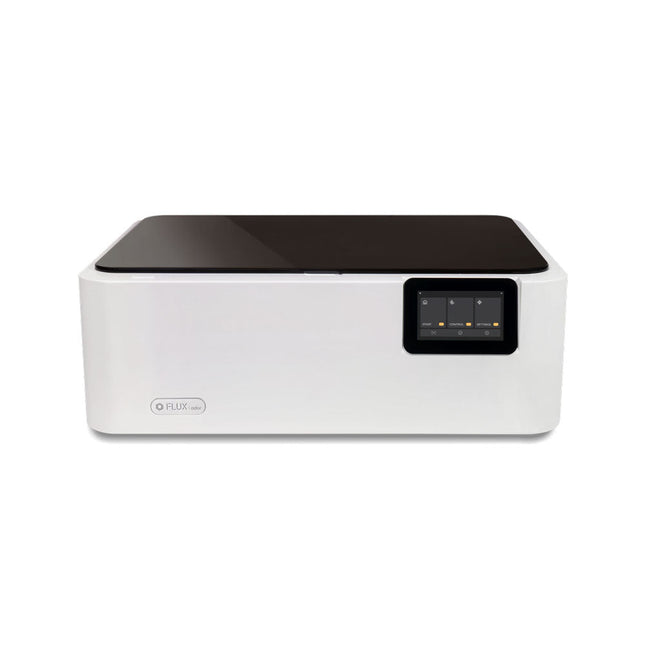
FLUX Ador is the world's first color printing laser cutter. Powered by three high-quality, interchangeable modules, Ador enables you to engrave and cut though a wide range of materials while enhancing your projects with a pop of color.
New creative potential with Ador
Whether you’re an educator, small business, crafter or designer, with Ador, the application boundary is for you to define.
Easy to use
Place material then autofocus
Drag and drop your design
Engrave, cut or print
Project Completed!
Big workspace, big ideas
Ador offers a big working space of 430 x 300 mm, with a depth of 30 mm, expanding the horizons of your creativity.
Specifications
Dimensions
637 x 488 x 226 mm
Weight
19 kg
Work Area
X&Y: 20 W Diode laser: 430 x 300 mm (X & Y varies with different modules)Z: 30 mm (for all modules) & 20 mm (with prism)
Camera Preview Area
Whole work area
Voltage
AC 110-240 V
Touch Panel
Yes, 8 inches (diagonal)
Camera
8 MP
I/O
USB / WiFi
Laser Spec
W Diode laser Module
Laser Moving Speed
0~400 mm/s
Laser Cutting Thickness
Varies for different materials
Software Mode
Vector / Graphic (monochrome, gray scale)
Operating System
Windows / macOS / Linux
Software File Type
JPG / PNG / SVG / DXF
Included
FLUX Ador
20 W diode laser module
6x prism lift
Power adapter
Power cord
Hex key
Vent Hose
Vent hose Duct Clamp
Wooden test piece
Laser Cutter Lubricant
Downloads
Firmware
The OWON ADS900A series is a compact 12-bit digital oscilloscope offering up to 2 GSa/s, 100 Mpts memory, and 125/250 MHz bandwidth. With its 7" multi-touch display, FFT, protocol decoding, and integrated logic analyzer, it delivers precise signal analysis for lab, workshop, and field applications.
Specifications
ADS914A
ADS924A
Bandwidth (-3 dB)
125 MHz
250 MHz
Channels
4
Max. sample rate
2 GSa/s (single-channel) 1 GSa/s (dual-channel) 500 MSa/s (full-channel)
DC Gain Accuracy
3% (≤1 mV)
2% (≥2 mV)
Max memory depth
100M
Vertical resolution
12 bits
Relay time accuracy
±25 ppm (typical)
Input Impedance
1 MΩ±2%, parallel with20 pF±5 pF
Probe Attenuation Coefficient
1.00μX-1M.00X,step by 1-2-5, support custom
Trigger type
Edge, Video, Pulse, Slope, Runt, Windows, Timeout, Nth, Logic, RS232/UART, I²C, SPI CAN, LIN
Bus decoding
RS232/UART, I²C, SPI, CAN, LIN
Auto measurement
Period, Frequency, +Width, -Width, Rise Time, Fall Time, Scr Duty, +Duty,-Duty, Vavg, Vpp, VRMS, Overshoot, Vmax, Vmin, Vtop, CycRms, Vbase, Vamp, Preshoot, Std Dev, +Pulse Cnt, -Pulse Cnt, Rise Cnt, Fall Cnt, Area, Cyc Area, Delay(A↑-B↑), Delay(A↑-B↓), Delay(A↓-B↑), Delay(A↓-B↓), Phase(A↑-B↑)
Phase(A↑-B↓), Phase(A↓-B↑), Phase(A↓-B↓), FRR(A↑-B↑), FRF(A↑-B↓)
FFR(A↓-B↑), FFF(A↓-B↓), LRR(A↑-B↑), LRF(A↑-B↓), LFR(A↓-B↑), LFF(A↓-B↓)
Waveform Math
+, -, *, /, &&, ||, ^, !, Intg, Diff, Sqrt, Function operation (Lg / Ln / Exp / Abs / Sine / Cosine / Tan), FFT, FFT rms, User Defined, digital filter (low pass, high pass, band pass, band reject)
Frequency counter
6-digit frequency counter
Maximum frequency: maximum analog bandwidth of oscilloscope
Voltmeter
Support DC, AC+DCrms, ACrms, Resolution: 4 digits (ACV/DCV)
Logical Analyzer Specifications
Number of channels
16 input channels (D0-D15) (D0 to D7, D8 to D15)
Max. input voltage
±40V peak CAT I, transient overvoltage 800Vpk
Input Impedance
100kΩ, 8 pF
Vertical resolution
1 bit
Other
Communication Interface
HDMI, USB device, USB Host, Trig Out (P/F), LAN
Display
7 inch (1024x600), capacitive multi-touch screen
Power supply interface
USB-C
Dimensions
260 x 160 x 78 mm
Weight
1.5 kg
Included
1x OWON ADS914A Oscilloscope
1x Power Adapter
1x Power Cord
1x USB Cable
1x Probe
1x Quick Guide
Downloads
Manual
Quick Guide
PC Software
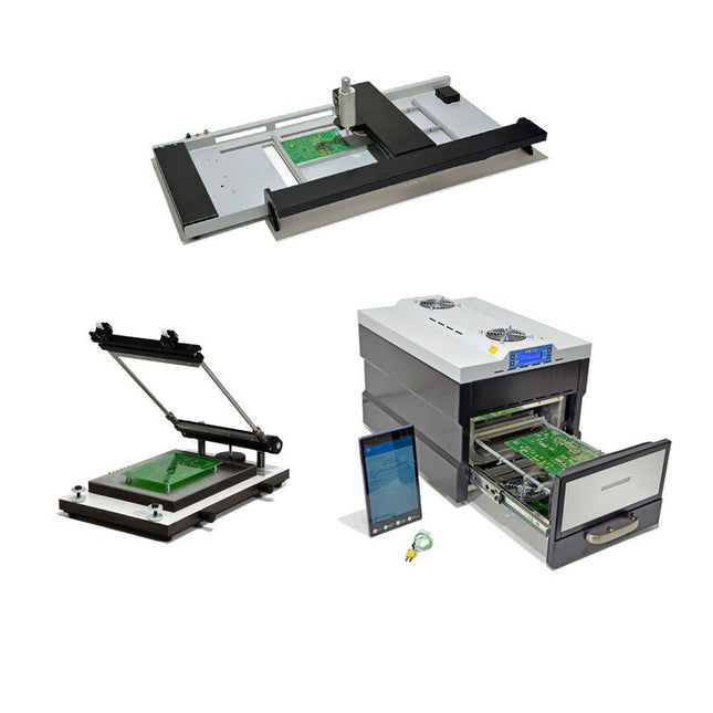
The SMD Starter I prototype production line consists of the stencil printer TSD240, the SMD placement device PlaceMAN and the reflow oven 3LHR10. Stencil printer SD240 (+ Metal Squeegee 155 mm) Stencil size: max. 175 x 255 mm PCB size: max. 180 x 240 mm Size: 410 x 270 x 110 mm Weight: 6.7 kg incl. metal squeegee 155 mm incl. 8 magnets to hold the PCB, 6 of them with M3 grub screw Manual SMD pick-and-place device PlaceMAN for standard components incl. vacuum pump (without feeders, camera, monitor and dispenser) Equipped with smooth-running placement arm, placement head with one-hand operation, rotation of the Z-axis and automatic vacuum switch-off, incl. PCB holder, vacuum unit and 2 placement needles with rubber suction cups. Capacity of feeder (not included) 2x feeder cassette for 10 x 8 mm wheels left 4x feeder cassette for rod feeders for 5 rods each Further feeding systems are possible within the assembly area, e.g. strip-feeder plug-in system Dimensions Base unit (LxWxH): 765 x 390 x 210 mm With feeder cassette for 10 x 8 mm rolls (LxWxH): 765 x 390 x 210 mm With feeder cassette for 10 x 8 mm rolls and feeder cassette for rod feeder (LxWxH): 765 x 430 x 210 mm (height may vary due to rod length) With feeder cassette for 10 x 8 mm rolls incl. holder for 10 rolls and feeder cassette for rod feeder (LxWxH): 765 x 430 x 210 mm (height may vary due to rod length) Specifications Weight of basic unit: approx. 6 kg Axis travel (x,y,z): 470 x 230 x 15 mm Max. working area: 380 x 240 mm Max. PCB size: 230 x 360 mm Power supply: 230/12 V, 800 mA Power supply vacuum pump: 230 V, 6 W 3LHR10 Reflow Oven (programmable for lead-free soldering with manual drawer and tablet control) Reflow oven with IR and convection heating. Forced hot air convection ensures a uniform temperature profile throughout the chamber. After manually opening the door, the fans are turned on and the soldered PCB is quickly cooled. Small reflow oven with manual door Industry 4.0 ready, Bluetooth communication + tablet IR + convection heating Android application to connect to tablet or smartphone 100 different user programs Delivery content: 3LHR10, tablet with app, protective cover for tablet, 4 PCB holders, external thermocouple, manual at tablet Application Connect the oven to the power supply and connect the optionally available extraction system (3LFE10S) to the exhaust air nozzle. After the first turn on, the oven will search for a tablet or smartphone. When both are connected to the Android app, choose the programming of the oven. Here, programmable temperature and preheating time as well as temperature and other data are to be set. Register with the tablet to use the full scope of the software. If the oven is already programmed, the user can control the operation with buttons and display at the front panel. When the reflow process is complete, an audible signal sounds. A signal is also displayed on the tablet/smartphone. The drawer must now be opened manually. The Android application displays process status, time and temperature or other information. Specifications Power supply: 230 V, 50 Hz Maximum power: 3100 W Temperatures: 50-260°C Dimensions: 510 x 370 x 340 mm Maximum weight: 16 kg Grid dimensions: 350 x 220 mm Maximum dimensions of the printed circuit board: 300 x 200 mm Maximum component height on the PCB: 50 mm at the top, 30 mm at the bottom Scope of delivery Stencil printer TSD240 SMD placement device PlaceMAN Reflow oven 3LHR10
Erste Schritte ins IoT - mit dem ESP32-C3WLAN-Taster und -Relais
IoT-Cloud à la ArduinoErster Kontakt mit der Arduino-Cloud
Arduino-Shield für zwei Geiger-Müller-ZählrohreEin hochempfindlicher, sehr stromsparender Strahlungsmesser
CO2-WächterEin DIY-Ansatz zur Überwachung der Luftqualität
MonkMakes: Luftqualitäts-Messgerätekit für den Raspberry PiMisst Temperatur und CO2e
Aller Anfang ...muss nicht schwer sein: Willkommen bei der Diode!
Beherrschen Sie die Fachsprache?Fünf praktische Tipps für Ingenieure
Tipps & Tricks beim BauteiltestRecycling ohne teures Messequipment
Stromsparende MaulwurfscheucheEin ATtiny13 ersetzt einen 555er
Lichtschalter DeLuxEine Lösung für hochpräzises lichtgesteuertes Schalten
Herausforderungen bei der Markteinführung von IoT-LösungenSorgen um Sicherheit, Skalierbarkeit und Wettbewerb
Infografik 5-6/2022
Lieber doch verkabeltTipps zur Entwicklung einer 1-Gbit/s-Schnittstelle im Industrieumfeld
Objekterkennung in Echtzeit für MCUs mit Edge Impulse FOMO
WanderfeldröhrenBemerkenswerte Bauteile
NB-IoT - ein ÜberblickStandards, Abdeckung, Verträge und Module
Dragino LPS8 Indoor GatewaySchnell zum eigenen LoRaWAN-Gateway
ATtiny-Mikrocontroller mit C und Assembler erforschenBeispiel-Kapitel: I/O-Ports des ATtiny
Projekt 2.0Korrekturen, Updates und Leserbriefe
LoRa-GPS-Tracker - ein UpdateDaten abholen und visualisieren mit dem Raspberry Pi
Schaltungssimulation mit TINA Design Suite und TINACloudBeispiel-Kapitel: Sinusförmige Oszillatoren
WinUI 3: Neues Grafik-Framework für Windows-AppsEine erste App für Elektroniker
GUIs mit Python:Die schlechteste GUI der Welt
Insel-SolaranlagenElektrische Energie unabhängig vom Netz
Das 10-Jahres-HandyErneuern Sie Ihre Erwartungen!
Hexadoku
The 2-channel OWON XDG2035 is a function/waveform generator that can generate signals with a maximum frequency of 35 Hz. The generator has a resolution of 1 µHz and a sample rate of 500 MSa/s.
The OWON XDG2035 is capable of generating 6 standard waveforms and 150 arbitrary waveforms. With the included software you can write advanced functions up to 10 million points. Waveforms can be saved to the function generator's internal memory using a PC via USB or LAN.
The OWON XDG2035 also supports SCPI commands and LabView. The function generator has an integrated high-quality frequency counter, which can operate from 100 to 200 MHz.
Features
Max. 35 MHz frequency output
500 MSa/s Sample rate, Vertical resolution 1μHz
14 bits Vertical Resolution, 10 Marb waveform length
Comprehensive waveform output: 6 basic waveforms,and 150 built-in arbitrary waveforms
Comprehensive modulation functions: AM, FM, PM, FSK, 3FSK, 4FSK, PSK, OSK, ASK, BPSK, PWM, Sweep, and Burst
High-accuracy frequency counter integrated, supported range 100-200 MHz
SCPI and LabVIEW supported
7 inch multi-touch screen (800 x 480 pixels)
Specifications
Channel
2
Frequency Output
35 MHz
Sample Rate
500 MSa/s
Vertical Resolution
14 bits
Waveform
Standard Waveform
sine, square, pulse, ramp, noise, and harmonic
Arbitrary Waveform
exponential rise, exponential fall, sin(x)/x, step wave, and others, total 150 built-in waveforms, and user-defined arbitrary waveform
Frequency (resolution 1 μHz)
Sine
1 μHz-100 MHz
Square
1 μHz ~ 30 MHz
Pulse
1 μHz ~ 25 MHz
Ramp
1 μHz ~ 3 MHz
Noise (-3 dB, typical)
100 MHz
Arbitrary Waveform
1 μHz ~ 15 MHz
Harmonic
1 μHz ~ 50 MHz
Accuracy
±2ppm, 25°C ±5°C
Waveform Length
2 points - 10M points
Amplitude
Into 50Ω load
1mVpp ~ 10Vpp (≤25 MHz); 1mVpp ~ 5Vpp (≤60 MHz); 1mVpp ~ 2.5Vpp (≤100 MHz)
Modulation
Type
AM, DSB-AM, FM, PM, ASK, FSK, PSK, BPSK, QPSK, 3FSK, 4FSK, OSK, PWM, SUM
Frequency Counter
Function
Frequency, period, +width, -width, +duty, and -duty
Frequency Range
100 ~ 200 MHz
Frequency Resolution
7 digits
Input/Output
Input mode
frequency counter, external modulation input, external trigger input, internal clock output, external reference clock input/output
Communication Interface
USB Host, USB Device, LAN, RS232 (optional)
Mechanical specifications
Dimensions
340 x 177 x 90 mm
Weight
2.3 kg
Included
1x OWON XDG2035
1x Power Cord
1x CD-ROM
1x Quick start guide
1x USB Cable
1x BNC-BNC Cable
Downloads
Quick Guide
The SQ series of handsfree PCBite probes from Sensepeek are insulated, come with included color-coded cable holders and have a lower point of gravity making them even more stable compared with the original SP series of probes. All the loved features of handsfree measurement, exchangeable fine pitch spring tipped test needle and the minimalistic design is maintained to make traditional sized and handheld probes obsolete.
Features
All handsfree probes from Sensepeek makes instant measurements or long triggering sessions a breeze.
No more soldering wires to connect your probe or complicated tools to setup, just positioning the probe needle on any test point or component in the signal path and release.
Saves time and frustration during development, verification and repairs.
The minimalist design and the spring-loaded test needle makes it possible to simultaneously measure on fine pitch components and nearby signals.
Both length and weight of the SQ probes are perfectly balanced to be used with PCBite PCB holders and base plate which is a must for handsfree function.
The probe holder comes with a powerful magnet in the base, as for all PCBite probes and holders which makes the probe easy to place and reposition.
The SQ series of probes can be used handheld without the probe holder as they have an insulated grip but their full potential is used when measuring handsfree.
Included
4x PCBite PCB holders
2x SQ10 probes and pin tipped test needles (red/black)
2x Banana to dupont test wires (red/black)
1x Large Base plate (A4)
1x Insulation cover for the base plate (A4)
1x Set of yellow insulation washers for the PCB holders
1x Set of cable holders (red/black)
2x Extra test needles
1x Micro fiber cloth
Downloads
User Guide (PCBite Kit)
User Guide (SQ10)
The Siglent SDS1204X-E is a powerful 200 MHz four-channel oscilloscope that is built on the same platform as the very popular SDS1202X-E but with several significant improvements, including two 1 GSa/s ADCs and two 14 Mpt memory modules. Waveform capture rates are up to 100,000 wfms/s in normal mode and 400,000 wfms/s in sequence mode. The SDS1000X-E scopes feature a large 7” 256-level color display with intensity grading and color temperature features.
Specifications
Bandwidth
200 MHz
Sampling Rate (Max.)
1 GSa/s
Channels
2CH+EXT4CH
Memory Depth (Max.)
7 Mpts/CH (not interleave mode); 14 Mpts/CH (interleave mode)
Waveform Capture Rate (Max.)
100,000 wfms/s (normal mode), 400,000 wfms/s (sequence mode)
Trigger Types
Edge, Slope, Pulse width, Window, Runt, Interval, Dropout, Pattern, Video
Serial Trigger (Standard)
I²C, SPI, UART/RS232, CAN, LIN
Decode Type (Standard)
I²C, SPI, UART/RS232, CAN, LIN
16 Digital Channels (four channel series only, option)
Maximum waveform capture rate up to 1 GSa/s, Record length up to 14 Mpts/CH
USB AWG module (four channel series only, option)
One channel, 25 MHz, sample rate of 125 MHz, wave length of 16 kpts
Bode plot ( four channel series only)
Minimum start frequency of 10 Hz, minimum scan bandwith of 500 Hz, maximum scan bandwidth of 120 MHz (dependent on Oscilloscope and AWG bandwidth), 500 maximum scan frequency points
USB WIFI adapter (four channel series only, option)
802.11b/g/b, WPA-PSK, the adapter must be supplied by Siglent to ensure proper functioning
Downloads
Datasheet
Manual
Programming Guide
Example projects with Node-RED, MQTT, WinCC SCADA, Blynk, and ThingSpeak
This comprehensive guide unlocks the power of Modbus TCP/IP communication with Arduino. From the basics of the Modbus protocol right up to full implementation in Arduino projects, the book walks you through the complete process with lucid explanations and practical examples.
Learn how to set up Modbus TCP/IP communication with Arduino for seamless data exchange between devices over a network. Explore different Modbus functions and master reading and writing registers to control your devices remotely. Create Modbus client and server applications to integrate into your Arduino projects, boosting their connectivity and automation level.
With detailed code snippets and illustrations, this guide is perfect for beginners and experienced Arduino enthusiasts alike. Whether you‘re a hobbyist looking to expand your skills or a professional seeking to implement Modbus TCP/IP communication in your projects, this book provides all the knowledge you need to harness the full potential of Modbus with Arduino.
Projects covered in the book:
TCP/IP communication between two Arduino Uno boards
Modbus TCP/IP communication within the Node-RED environment
Combining Arduino, Node-RED, and Blynk IoT cloud
Interfacing Modbus TCP/IP with WinCC SCADA to control sensors
Using MQTT protocol with Ethernet/ESP8266
Connecting to ThingSpeak IoT cloud using Ethernet/ESP8266