
Search results for "seminar OR c OR programmierung OR mikrocontroller OR programm"
-
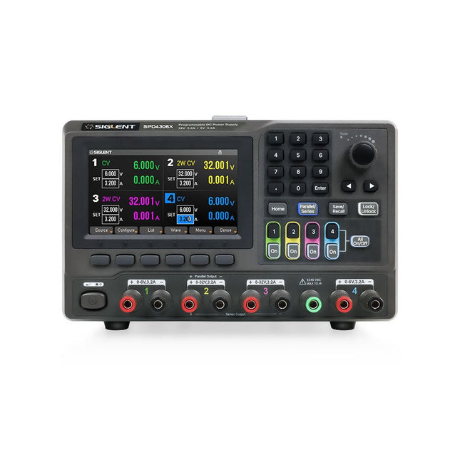
Siglent Siglent SPD4306X 4-ch DC Power Supply (400 W)
The Siglent SPD4306X is a 4-channel DC Linear Programmable Power Supply equipped with a 4.3-inch TFT-LCD display, friendly human-machine interface, and excellent performance indicators. Real-time waveform display provides engineers with an informative user interface. SPD4306X offers a total output power of 400 W with a resolution of 1 mV/1 mA. The maximum voltage and current for each channel are as follows: CH1: 15 V/1.5 A CH2: 30 V/6 A CH3: 30 V/6 A CH4: 15 V/1 A Features Rated output power: 400 W Rated voltage: 32 V, 12 V, 30 V Up to four high-precision power supplies with independent controllable outputs, supporting CH2 and CH3 series and parallel connections Clear graphical interface with waveform and timer display modes 5-digit voltage and current display with minimum resolution of 1 mV, 1 mA Fast output response time: <50us The high current channel support remote voltage compensation sense function. The maximum compensation voltage is 0.6 V Overvoltage protection and overcurrent protection or safe and accurate operation Equipped with a 4.3-inch TFT-LCD display (480 x 272 resolution) USB and LAN standard communication USB-GPIB module is optional Excellent channel density with up to 4 channels in a 3U half rack package Internal data storage for setups and parameters Embedded Web Server with instrument communication that doesn’t require software installation Fully SCPI programming command set support as well as a LabView driver for remote control and system automation Specifications SPD4323X SPD4121X SPD4306X Channel Output CH1: Voltage 0 to 6 V Current 0 to 3.2 ACH2: Voltage 0 to 32 V Current 0 to 3.2 ACH3: Voltage 0 to 32 V Current 0 to 3.2 ACH4: Voltage 0 to 6 V Current 0 to 3.2 A CH1: Voltage 0 to 15 V Current 0 to 1.5 ACH2: Voltage 0 to 12 V Current 0 to 10 ACH3: Voltage 0 to 12 V Current 0 to 10 ACH4: Voltage 0 to 15 V Current 0 to 1.5 A CH1: Voltage 0 to 15 V Current 0 to 1.5 ACH2: Voltage 0 to 30 V Current 0 to 6 ACH3: Voltage 0 to 30 V Current 0 to 6 ACH4: Voltage 0 to 15 V Current 0 to 1 A Resolution 1 mV, 1 mA 1 mV, 1 mA 1 mV, 1 mA Setting Accuracy Voltage: ±(0.03% of reading+10) mV, Current: ±(0.3% of reading+10) mA Voltage: ±(0.03% of reading+10) mV, Current: ±(0.3% of reading+10) mA Voltage: ±(0.03% of reading+10) mV, Current: ±(0.3% of reading+10) mA Readback Accuracy Voltage: ±(0.03% of reading+10) mV, Current: ±(0.3% of reading+10) mA Voltage: ±(0.03% of reading+10) mV, Current: ±(0.3% of reading+10) mA Voltage: ±(0.03% of reading+10) mV, Current: ±(0.3% of reading+10) mA Display 4.3" TFT-LCD 5-digit voltage and current display 4.3" TFT-LCD 5-digit voltage and current display 4.3" TFT-LCD 5-digit voltage and current display Output power 240 W 285 W 400 W Included 1x Siglent SPD4306X Power Supply 1x Power cord (EU) 1x Output test cord (3 A) 1x USB cable 1x Quick start guide Downloads Datasheet Manual Quick start
€ 1.101,10
-

OWON OWON HDS242 2-ch Oscilloscope (40 MHz) + Multimeter
The HDS242 is a portable 2-in-1 multifunctional tester, which can be used as a 2-ch oscilloscope and multimeter. It features a high-contrast 3.5-inch color display suitable for outdoor facility maintenance, rapid on-site measurement, automobile maintenance, power detection. etc. Features Oscilloscope + Multimeter 3.5-inch high-resolution, high-contrast color LCD display – suitable for outdoor use 18650 lithium battery – can work continuously for up to 6 hours USB-C interface – support power bank and PC connection Self-calibration function SCPI supported – facilitate secondary development Specifications Oscilloscope Bandwidth 40 MHz Channels 2-ch Oscilloscope Sample Rate 250 MSa/s Acquisition Model Normal, Peak detect Record Length 8K Display 3.5-inch LCD Waveform Refresh Rate 10,000 wfrms/s Input Coupling DC, AC, and Ground Input Impedance 1 MΩ ±2%, in parallel with 16pF ±10pF Probe Attenuation Factors 1X, 10X, 100X, 1000X, 10000X Max. Input Voltage 400 V (DC+AC, PK-PK, 1MΩ input impedance) (10:1 probe attenuation) Bandwidth Limit (typical) 20 MHz Horizontal Scale 5ns/div - 1000s/div, step by 1 - 2 - 52ns/div - 1000s/div, step by 1 - 2 - 55ns/div - 1000s/div, step by 1 - 2 - 52ns/div - 1000s/div, step by 1 - 2 - 5 Vertical Sensitivity 10mV/div - 10V/div Vertical Resolution 8 bits Trigger Type Edge Trigger Modes Auto, Normal, single Automatic Measurement Frequency, Period, Amplitude, Max, Min, Mean, PK-PK Cursor Measurement ΔV, ΔT, ΔT & ΔV between cursors Multimeter Max. Resolution 20,000 counts Testing Mode Voltage, Current, Resistance, Capacitance, Diode, and Continuity test Input Impedance 10 MΩ Max Input Voltage AC: 750 V | DC: 1000 V Max Input Current DC: 10 A | AC: 10 A Diode 0-2 V Other Connectivity USB Type-C Dimensions 198 x 96 x 38 mm (7.68 x 3.74 x 1.5') Weight 600 g (without batteries) Included 1x OWON HDS242 Oscilloscope 1x Soft Bag 1x Probe 1x Power Cord 1x Probe Adjust 1x USB Cable 1x Power Adapter 1x Pair of Multimeter Probe Leads (red one and black one) 1x Pair of Oscilloscope Probe Leads (BNC to Alligator Clip) 1x User Manual (English) Downloads User Manual SCPI Protocol Quick Guide PC Software
€ 112,87
-

Weller Weller WE1010 Digital Soldering Station (70 W)
High-quality soldering station with the most important tools and consumables, ideal for universal soldering applications. Features 1-Channel Power Unit, digital, 70 W Power unit, 1 channel with soldering iron WEP 70 and safety rest PH 70 70W solder iron with ergonomic handle and providing toolless tip change ESD safe station, iron and heat-resistant silicon cable for safe handling Using ET soldering tips Standby mode and auto setback conserves energy, protects equipment Password-protected to preserve settings Specifications Dimensions: 150 x 120 x 98 mm Weight: 1.4 kg Display: Digital LC Display Temperature range: Adjustable from 100°C - 450°C (200°F - 850°F) Voltage: 230 V Channels: 1 Temperature range (depends on tool) °C: 100-450 Temperature range (depends on tool) °F: 200-850 Temperature accuracy °C: Average tip temperature can be „offset“ to +/- 5°C at idle with no load Temperature accuracy °F: Average tip temperature can be „offset“ to +/- 9°F at idle with no load Temperature stability °C: ±6 Temperature stability °F: ±10 Heat-up time (ca) in seconds (50-350°C / 120-660°F): 28 sec. Heating output: 85 W
€ 157,60
-

Elektor Digital Röhren 8 (PDF)
Aus dem Inhalt Sieben Jahre Elektor Röhren-Sonderhefte Der Kompressionseffekt oder das Geheimnis des Schirmgitters Phasenumkehrstufen Gitterwiderstand und Gitterstrom Eintakt-A-Endstufe mit der 6C33 Single-Ended-Endstufe mit der legendären Röhre 300B Eintaktverstärker: Eine Handvoll gutklingender Watt Parallel-Push-Pull-Monoblock mit 140 Watt Ruhestromsteuerung von Röhrenendstufen mithilfe eines Mikrocontrollers Kompakter Stereo-Röhrenverstärker mit der ECL 85 2-V-1-Audion für Mittel- und Kurzwelle Hi-Fi-Röhren-Endstufe Das Klanggeheimnis von sauerstofffreiem Kupferkabel Stereo-Basisbreite Röhrendaten mit Sockelschaltungen
€ 17,50
Members: € 15,75
-

OWON OWON SPS6051 Fanless DC Power Supply (150 W)
The OWON SPS6051 Fanless Programmable DC Power Supply (150 W) delivers ultra-quiet, high-precision performance with 10 mV/1 mA accuracy and advanced heat dissipation for long-term reliability. Featuring comprehensive protection, a USB interface with SCPI support for remote control, and a 2.8-inch TFT LCD screen, it is the perfect choice for laboratories, electronics testing, and research. Features Fanless design: Ultra-quiet operation, reducing vibration noise and minimizing the potential failure risks associated with traditional cooling fans. Excellent heat dissipation design: Ensures a controlled temperature rise, allowing long-term operation under full load conditions and extending internal component longevity. Lightweight and ultra-thin design. Output accuracy up to 10 mV/1 mA. Supports List waveform editing and output, with four memory shortcut parameters for quick and convenient access. Integrated protection features include overvoltage, overcurrent, overtemperature, and input undervoltage protection for enhanced safety. Built-in discharge circuit prevents residual high voltage risks when the power is turned off. USB communication interface with SCPI protocol support, enabling PC programming and remote control for simplified user management. 2.8-inch TFT LCD screen Specifications Model SPS6051 SPS3081 Rated Output (0°C-40°C) Voltage 0-61 V 0-31 V Current 0-5.1 A 0-8.1 A Power 150 W 120 W Load Regulation Voltage ≤30 mV Current ≤20 mA Power Regulation Voltage ≤30 mV Current ≤20 mA Setting Resolution Voltage 10 mV Current 1 mA Readback Resolution Voltage 10 mV Current 1 mA Seting Accuracy (25°C ±5°C) Voltage ≤0.05% ±20 mV ≤0.1% ±20 mV Current ≤0.05% ±20 mA ≤0.2% ±20 mA Readback Accuracy (25°C ±5°C) Current ≤0.05% ±20 mV ≤0.1% ±20 mV Voltage ≤0.05% ±20 mV ≤0.2% ±20 mA Ripple/Noise Voltage ≤30 mVp-p ≤30 mVp-p Voltage ≤4 mVrms ≤5 mVrms Current ≤10 mAp-p ≤30 mAp-p Output temperature coefficient (0°C-40°C) Voltage 100 ppm/°C Current 200 ppm/°C Readback temperature coefficient Voltage 100 ppm/°C Current 200 ppm/°C Response Time (50-100% rated load) ≤1.0 ms Storage 4 groups of data Working Temperature 0-40°C Display 2.8-inch color LCD display Interface USB Dimensions (W x H x D) 82 x 142 x 226 mm Weight 1.8 kg Included 1x OWON SPS6051 Power Supply 2x Test leads 1x Power cord 1x Manual Downloads Datasheet User Manual Programming Manual PC Software
€ 134,31
-
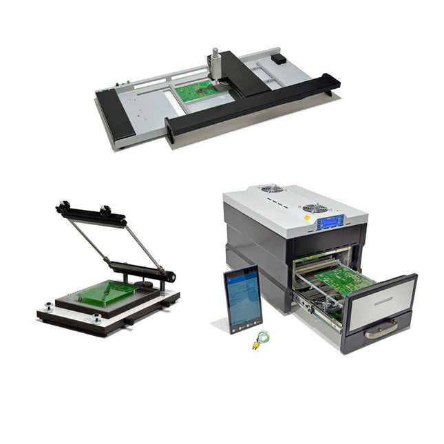
Paggen Werkzeugtechnik SMD Starter I – Production Line for Prototypes
The SMD Starter I prototype production line consists of the stencil printer TSD240, the SMD placement device PlaceMAN and the reflow oven 3LHR10. Stencil printer SD240 (+ Metal Squeegee 155 mm) Stencil size: max. 175 x 255 mm PCB size: max. 180 x 240 mm Size: 410 x 270 x 110 mm Weight: 6.7 kg incl. metal squeegee 155 mm incl. 8 magnets to hold the PCB, 6 of them with M3 grub screw Manual SMD pick-and-place device PlaceMAN for standard components incl. vacuum pump (without feeders, camera, monitor and dispenser) Equipped with smooth-running placement arm, placement head with one-hand operation, rotation of the Z-axis and automatic vacuum switch-off, incl. PCB holder, vacuum unit and 2 placement needles with rubber suction cups. Capacity of feeder (not included) 2x feeder cassette for 10 x 8 mm wheels left 4x feeder cassette for rod feeders for 5 rods each Further feeding systems are possible within the assembly area, e.g. strip-feeder plug-in system Dimensions Base unit (LxWxH): 765 x 390 x 210 mm With feeder cassette for 10 x 8 mm rolls (LxWxH): 765 x 390 x 210 mm With feeder cassette for 10 x 8 mm rolls and feeder cassette for rod feeder (LxWxH): 765 x 430 x 210 mm (height may vary due to rod length) With feeder cassette for 10 x 8 mm rolls incl. holder for 10 rolls and feeder cassette for rod feeder (LxWxH): 765 x 430 x 210 mm (height may vary due to rod length) Specifications Weight of basic unit: approx. 6 kg Axis travel (x,y,z): 470 x 230 x 15 mm Max. working area: 380 x 240 mm Max. PCB size: 230 x 360 mm Power supply: 230/12 V, 800 mA Power supply vacuum pump: 230 V, 6 W 3LHR10 Reflow Oven (programmable for lead-free soldering with manual drawer and tablet control) Reflow oven with IR and convection heating. Forced hot air convection ensures a uniform temperature profile throughout the chamber. After manually opening the door, the fans are turned on and the soldered PCB is quickly cooled. Small reflow oven with manual door Industry 4.0 ready, Bluetooth communication + tablet IR + convection heating Android application to connect to tablet or smartphone 100 different user programs Delivery content: 3LHR10, tablet with app, protective cover for tablet, 4 PCB holders, external thermocouple, manual at tablet Application Connect the oven to the power supply and connect the optionally available extraction system (3LFE10S) to the exhaust air nozzle. After the first turn on, the oven will search for a tablet or smartphone. When both are connected to the Android app, choose the programming of the oven. Here, programmable temperature and preheating time as well as temperature and other data are to be set. Register with the tablet to use the full scope of the software. If the oven is already programmed, the user can control the operation with buttons and display at the front panel. When the reflow process is complete, an audible signal sounds. A signal is also displayed on the tablet/smartphone. The drawer must now be opened manually. The Android application displays process status, time and temperature or other information. Specifications Power supply: 230 V, 50 Hz Maximum power: 3100 W Temperatures: 50-260°C Dimensions: 510 x 370 x 340 mm Maximum weight: 16 kg Grid dimensions: 350 x 220 mm Maximum dimensions of the printed circuit board: 300 x 200 mm Maximum component height on the PCB: 50 mm at the top, 30 mm at the bottom Scope of delivery Stencil printer TSD240 SMD placement device PlaceMAN Reflow oven 3LHR10
€ 6.549,00
Best Price
-

Elektor Bundles Mikrocontroller-Praxiskurs für Arduino-Einsteiger (Bundle)
Mit dem Elektor Arduino Nano Trainingsboard (MCCAB) eigene Projekte realisieren Der Mikrocontroller ist das wohl faszinierendste Teilgebiet der Elektronik, denn aufgrund der Vielzahl von Funktionen, die er auf seinem Chip vereinigt, ist er für den Entwickler ein universelles Multi-Tool zur Realisierung seiner Projekte. Praktisch jedes Gerät des täglichen Gebrauchs wird heute von einem Mikrocontroller gesteuert. Für einen elektronischen Laien blieb es aufgrund der Komplexität bisher allerdings ein Wunschtraum, eigene Ideen mit einem Mikrocontroller zu realisieren. Das Arduino-Konzept hat den Einsatz von Mikrocontrollern weitgehend vereinfacht, sodass jetzt auch Laien eigene Elektronik-Ideen mit einem Mikrocontroller verwirklichen können. Buch & Hardware im Bundle: 'Learning by Doing' Dieses im Bundle mitgelieferte Buch (im großen A4-Format) zeigt, wie man auch ohne große Erfahrung in Elektronik und Programmiersprachen eigene Projekte mit einem Mikrocontroller realisieren kann. Es ist ein Mikrocontroller-Praxiskurs für Einsteiger, denn nach einem Überblick über die Interna des Mikrocontrollers und einer Einführung in die Programmiersprache C liegt der Schwerpunkt des Kurses auf den praktischen Übungen. Der Leser eignet sich die erforderlichen Kenntnisse durch 'Learning by Doing' an: in dem umfangreichen Praxisteil mit 12 Projekten und 46 Übungen wird das im vorderen Teil des Buches Gelernte mit vielen Beispielen unterlegt. Die Übungen sind dabei so aufgebaut, dass der Bearbeiter eine Aufgabenstellung erhält, die er mit seinem im Theorieteil des Buches aufgebauten Wissen löst. Für jede Übung gibt es anschließend eine ausführlich erklärte und kommentierte Musterlösung, die dem Bearbeiter bei Problemen weiterhilft und die er mit seiner eigenen Lösung vergleichen kann. Arduino IDE In der Arduino IDE, einer Software-Entwicklungsumgebung, die kostenlos auf den eigenen PC heruntergeladen werden kann und die das gesamte Softwarepaket enthält, das für ein eigenes Mikrocontroller-Projekt benötigt wird, schreibt der Bearbeiter mit dem Editor der IDE seine Programme („Apps“) in der Programmiersprache C. Der in die Arduino IDE integrierte Compiler übersetzt sie in die Bits und Bytes, die der Mikrocontroller versteht und die dann über ein USB-Kabel in den Speicher des Mikrocontrollers auf dem Elektor Arduino Nano Trainingsboard (MCCAB) geladen werden. Externe Sensoren, Motoren oder Baugruppen abfragen oder steuern Das Elektor Arduino Nano Trainingsboard (MCCAB) enthält neben einem Mikrocontrollermodul Arduino Nano alle für die Übungen benötigten Bauteile wie Leuchtdioden, Schalter, Taster, akustische Signalgeber usw. Auch externe Sensoren, Motoren oder Baugruppen können mit diesem Mikrocontroller-Übungssystem abgefragt oder gesteuert werden. Technische Daten (Arduino Nano Trainingsboard MCCAB) Stromversorgung Über die USB-Verbindung des zur Erstellung der Programme sowieso angeschlossenen PCs oder ein externes Netzteil (nicht im Lieferumfang enthalten) Betriebsspannung +5 Vcc Eingangsspannung Alle Eingänge 0 V bis +5 V VX1 und VX2 +8 V bis +12 V (nur bei Verwendung eines externen Netzteils) Mikrocontrollermodul Arduino Nano Hardwareperipherie LCD 2x16 Zeichen Potenziometer P1 & P2 JP3: Auswahl der Betriebsspannung von P1 & P2 Verteiler SV4: Verteiler für die BetriebsspannungenSV5, SV6: Verteiler für die Ein-/Ausgänge des Mikrocontrollers Schalter und Taster RESET-Taster auf dem Arduino Nano-Modul6x Tastschalter K1 … K66x Schiebeschalter S1 … S6JP2: Verbindung der Schalter mit den Eingängen des Mikrocontrollers Summer Piezo-Summer Buzzer1 mit Steckbrücke auf JP6 Leuchtanzeigen LED L auf dem Arduino Nano-Modul, verbunden mit GPIO D1311x LED: Zustandsanzeige für die Ein-/AusgängeJP6: Verbindung der LEDs LD10 … LD20 mit den GPIOs D2 … D12 Serielle SchnittstellenSPI & I²C JP4: Auswahl des Signals an Pin X der SPI-Steckerleiste SV12SV9 bis SV12: SPI-Interface (3,3 V/5 V) bzw. I²C-Interface Schaltausgang für externe Geräte SV1, SV7: Schaltausgang (maximal +24 V/160 mA, extern zugeführt)SV2: 2x13 Pins zum Anschluss externer Module 3x3 LED-Matrix (9 rote LEDs) SV3: Spalten der 3x3 LED-Matrix (Ausgänge D6 … D8)JP1: Verbindung der Reihen mit den GPIOs D3 … D5 Software Library MCCABLib Steuerung der Hardware-Komponenten (Schalter, Taster, Leuchtdioden, 3x3 LED-Matrix, Summer) auf dem MCCAB Trainingsboard Betriebstemperatur bis +40 °C Abmessungen 100 x 100 x 20 mm Technische Daten (Arduino Nano) Mikrocontroller ATmega328P Architektur AVR Betriebsspannung 5 V Flashspeicher 32 KB, davon 2 KB vom Bootloader belegt SRAM 2 KB Taktfrequenz 16 MHz Analoge IN-Pins 8 EEPROM 1 KB DC-Strom pro I/O-Pin 40 mA an einem I/O-Pin, insgesamt maximal 200 mA an allen Pins gemeinsam Eingangsspannung 7-12 V Digitale I/O-Pins 22 (6 davon sind PWM-fähig) PWM-Ausgänge 6 Stromverbrauch 19 mA Abmessungen 18 x 45 mm Gewicht 7 g Lieferumfang Elektor Arduino Nano MCCAB Trainingsboard Arduino Nano Buch: Mikrocontroller-Praxiskurs für Arduino-Einsteiger
-

NXP Semiconductors NXP FRDM-MCXN947 Development Board
The FRDM-MCXN947 is a compact and versatile development board designed for rapid prototyping with MCX N94 and N54 microcontrollers. It features industry-standard headers for easy access to the MCU's I/Os, integrated open-standard serial interfaces, external flash memory, and an onboard MCU-Link debugger. Specifications Microcontroller MCX-N947 Dual Arm Cortex-M33 cores @ 150 MHz each with optimized performance efficiency, up to 2 MB dual-bank flash with optional full ECC RAM, External flash Accelerators: Neural Processing Unit, PowerQuad, Smart DMA, etc. Memory Expansion *DNP Micro SD card socket Connectivity Ethernet Phy and connector HS USB-C connectors SPI/I²C/UART connector (PMOD/mikroBUS, DNP) WiFi connector (PMOD/mikroBUS, DNP) CAN-FD transceiver Debug On-board MCU-Link debugger with CMSIS-DAP JTAG/SWD connector Sensor P3T1755 I³C/I²C Temp Sensor, Touch Pad Expansion Options Arduino Header (with FRDM expansion rows) FRDM Header FlexIO/LCD Header SmartDMA/Camera Header Pmod *DNP mikroBUS User Interface RGB user LED, plus Reset, ISP, Wakeup buttons Included 1x FRDM-MCXN947 Development Board 1x USB-C Cable 1x Quick Start Guide Downloads Datasheet Block diagram
-
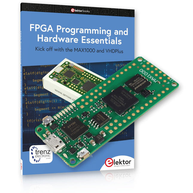
Elektor Bundles MAX1000 FPGA Programming Bundle
Kick off to FPGA Programming with the MAX1000 Board and VHDPlus Ready to master FPGA programming? With this bundle, you'll dive into the world of Field-Programmable Gate Arrays (FPGAs) – a configurable integrated circuit that can be programmed after manufacturing. Bring your ideas to life, from simple projects to complete microcontroller systems! The MAX1000 is a compact and powerful FPGA development board packed with features like memory, user LEDs, push-buttons, and flexible I/O ports. It’s the ideal starting point for anyone wanting to learn about FPGAs and Hardware Description Languages (HDLs). With the enclosed book "FPGA Programming and Hardware Essentials" you'll get hands-on with the VHDPlus programming language – a simpler version of VHDL. You'll work on practical projects using the MAX1000, helping you gain the skills and confidence to unleash your creativity. Projects in the Book Arduino-driven BCD to 7-Segment Display Decoder Use an Arduino Uno R4 to supply BCD data to the decoder, counting from 0 to 9 with a one-second delay Multiplexed 4-Digit Event Counter Create an event counter that displays the total count on a 4-digit display, incrementing with each button press PWM Waveform with Fixed Duty Cycle Generate a PWM waveform at 1 kHz with a fixed duty cycle of 50% Ultrasonic Distance Measurement Measure distances using an ultrasonic sensor, displaying the results on a 4-digit 7-segment LED Electronic Lock Build a simple electronic lock using combinational logic gates with push buttons and an LED output Temperature Sensor Monitor ambient temperature with a TMP36 sensor and display the readings on a 7-segment LED MAX1000 FPGA Development Board The MAX1000 is a customizable IoT/Maker Board ready for evaluation, development and/or use in a product. It is built around the Intel MAX10 FPGA, which is the industry’s first single chip, non-volatile programmable logic device (PLDs) to integrate the optimal set of system components. Users can now leverage the power of tremendous re-configurability paired with a high-performance, low-power FPGA system. Providing internally stored dual images with self-configuration, comprehensive design protection features, integrated ADCs and hardware to implement the Nios II 32-bit microcontroller IP, MAX10 devices are ideal solution for system management, protocol bridging, communication control planes, industrial, automotive and consumer applications. The MAX1000 is equipped with an Arrow USB Programmer2, SDRAM, flash memory, accelerometer sensor and PMOD/Arduino MKR connectors making it a fully featured plug and play solution without any additional costs. Specifications MAX 10 8 kLE - Flash Dual inside - ADC 8x 12 Bit - Temperature Range 0~85°C - Supply USB/pins SDRAM 8 MB 3-axis MEMS LIS3DH USB Programmer on board MEMS Oscillator 12 MHz Switch/LED 2x / 8x Contents of the Bundle Book: FPGA Programming and Hardware Essentials (normal price: €40) MAX1000 FPGA Development Board (normal price: €45) Downloads Software
-

SunFounder SunFounder Kepler Kit (Ultimate Starter Kit for Raspberry Pi Pico W)
Your gateway to IoT and microcontroller programming With 450+ components and 117 online projects, this comprehensive kit ignites your creativity. The tutorials by Paul McWhorter make learning enjoyable for beginners and advanced users. This kit supports MicroPython, C/C++, and Piper Make, offering diverse programming options. Explore sensors, actuators, LEDs, and LCDs for endless project possibilities. From home automation to robotics, this kit empowers your tech journey. Features IoT Starter Kit for Beginners: This kit offers a rich IoT learning experience for beginners. With 450+ components, 117 projects, and expert-led video lessons, this kit makes learning microcontroller programming and IoT engaging and accessible. Expert-Guided Video Lessons: The kit includes 27 video tutorials by the renowned educator, Paul McWhorter. His engaging style simplifies complex concepts, ensuring an effective learning experience in microcontroller programming. Wide Range of Hardware: The kit includes a diverse array of components like sensors, actuators, LEDs, LCDs, and more, enabling you to experiment and create a variety of projects with the Raspberry Pi Pico W. Supports Multiple Languages: The kit offers versatility with support for three programming languages - MicroPython, C/C++, and Piper Make, providing a diverse programming learning experience. Dedicated Support: Benefit from our ongoing assistance, including a community forum and timely technical help for a seamless learning experience. Included Raspberry Pi Pico W Breadboard Jumper Wires Resistor Transistor Capacitor Diode Li-po Charger Module 74HC595 TA6586 – Motor Driver Chip LED RGB LED LED Bar Graph 7-segment Display 4-Digit 7-Segment Display LED Dot Matrix I²C LCD1602 WS2812 RGB 8 LEDs Strip Buzzer DC Motor Servo DC Water Pump Relay Button Micro Switch Slide Switch Potentiometer Infrared Receiver Joystick Module 4x4 Keypad MPR121 Module MFRC522 Module Photoresistor Thermistor Tilt Switch Reed Switch PIR Motion Sensor Module Water Level Sensor Module Ultrasonic Module DHT11 Humiture Sensor MPU6050 Module Documentation Online Tutorials in 3 languages (EN, DE and JP)
-
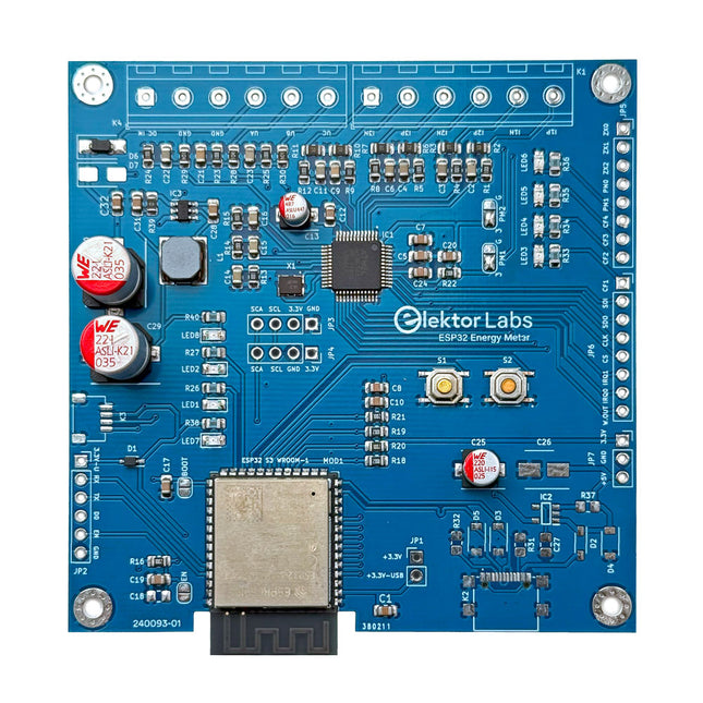
Elektor Labs Elektor ESP32 Energy Meter
The Elektor ESP32 Energy Meter is a device designed for real-time energy monitoring and smart home integration. Powered by the ESP32-S3 microcontroller, it offers robust performance with modular and scalable features. The device uses a 110/230 VAC to 12 VAC step-down transformer for voltage sampling, ensuring galvanic isolation and safety. Its compact PCB layout includes screw-type terminal blocks for secure connections, a Qwiic connector for additional sensors, and a programming header for direct ESP32-S3 configuration. The energy meter is compatible with single-phase and three-phase systems, making it adaptable for various applications. The energy meter is simple to set up and integrates with Home Assistant, offering real-time monitoring, historical analytics, and automation capabilities. It provides accurate measurements of voltage, current, and power, making it a valuable tool for energy management in homes and businesses. Features Comprehensive Energy Monitoring: Get detailed insights into your energy usage for smarter management and cost savings. Customizable Software: Tailor functionality to your needs by programming and integrating custom sensors. Smart Home Ready: Compatible with ESPHome, Home Assistant, and MQTT for full Smart Home integration. Safe & Flexible Design: Operates with a 110/230 VAC to 12 VAC step-down transformer and features a pre-assembled SMD board. Quick Start: Includes one Current Transformer (CT) sensor and access to free setup resources. Specifications Microcontroller ESP32-S3-WROOM-1-N8R2 Energy Metering IC ATM90E32AS Status Indicators 4x LEDs for power consumption indication2x Programmable LEDs for custom status notifications User Input 2x Push buttons for user control Display Output I²C OLED display for real-time power consumption visualization Input Voltage 12~16 VAC (via a step-down transformer 110/230 VAC to 12 VAC) Clamp Current Sensor YHDC SCT013-000 (100 A/50 mA) included Smart Home Integration ESPHome, Home Assistant, and MQTT for seamless connectivity Connectivity Header for programming, Qwiic for sensor expansion Applications Supports single-phase and three-phase energy monitoring systems Dimensions 79.5 x 79.5 mm Included 1x Partly assembled board (SMDs are pre-mounted) 2x Screw terminal block connectors (not mounted) 1x YHDC SCT013-000 current transformer Required Power transformer not included Downloads Datasheet (ESP32-S3-WROOM-1) Datasheet (ATM90E32AS) Datasheet (SCT013-000) Frequently Asked Questions (FAQ) From Prototype to Finished Product What started as an innovative project to create a reliable and user-friendly energy meter using the ESP32-S3 microcontroller has evolved into a robust product. Initially developed as an open-source project, the ESP32 Energy Meter aimed to provide precise energy monitoring, smart home integration and more. Through meticulous hardware and firmware development, the energy meter now stands as a compact, versatile solution for energy management.
-
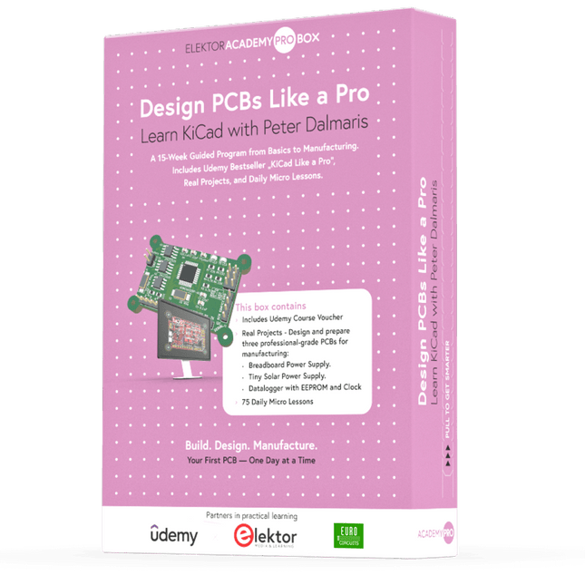
Elektor Academy Pro Design PCBs Like a Pro
Learn KiCad with Peter Dalmaris The Academy Pro Box "Design PCBs like a Pro" offers a complete, structured training programme in PCB design, combining online learning with practical application. Based on Peter Dalmaris’ KiCad course, the 15-week programme integrates video lessons, printed materials (2 books), and hands-on projects to ensure participants not only understand the theory but also develop the skills to apply it in practice. Unlike standard courses, the Academy Pro Box provides a guided learning path with weekly milestones and physical components to design, test, and produce working PCBs. This approach supports a deeper learning experience and better knowledge retention. The box is ideal for engineers, students, and professionals who want to develop practical PCB design expertise using open-source tools. With the added option to have their final project manufactured, participants complete the programme with real results – ready for use, testing, or further development. Learn by doing Build skills. Design real boards. Generate Gerbers. Place your first order. This isn’t just a course – it’s a complete project journey from idea to product. You’ll walk away with: Working knowledge of KiCad’s tools Confidence designing your own PCBs A fully manufacturable circuit board – made by you What's inside the Box (Course)? Both volumes of "KiCad Like a Pro" (valued at €105) Vol 1: Fundamentals and Projects Vol 2: Advanced Projects and Recipes Coupon code to join the bestselling KiCad 9 online course by Peter Dalmaris on Udemy, featuring 20+ hours of video training. You'll complete three full design projects: Breadboard Power Supply Tiny Solar Power Supply Datalogger with EEPROM and Clock Voucher from Eurocircuits for the production of PCBs (worth €85 excl. VAT) Learning Material (of this Box/Course) 15-Week Learning Program ▶ Click here to open Week 1: Setup, Fundamentals, and First Steps in PCB Design Week 2: Starting Your First PCB Project – Schematic Capture Week 3: PCB Layout – From Netlist to Board Design Week 4: Design Principles, Libraries, and Workflow Week 5: Your First Real-World PCB Project Week 6: Custom Libraries – Symbols, Footprints, and Workflow Week 7: Advanced Tools – Net Classes, Rules, Zones, Routing Week 8: Manufacturing Files, BOMs, and PCB Ordering Week 9: Advanced Finishing Techniques – Graphics, Refinement, and Production Quality Week 10: Tiny Solar Power Supply – From Schematic to Layout Week 11: Tiny Solar Power Supply – PCB Layout and Production Prep Week 12: ESP32 Clone Project – Schematic Design and Layout Prep Week 13: ESP32 Clone – PCB Layout and Manufacturing Prep Week 14: Final Improvements and Advanced Features Week 15: Productivity Tools, Simulation, and Automation KiCad Course with 18 Lessons on Udemy (by Peter Dalmaris) ▶ Click here to open Introduction Getting started with PCB design Getting started with KiCad Project: A hands-on tour of KiCad (Schematic Design) Project: A hands-on tour of KiCad (Layout) Design principles and PCB terms Design workflow and considerations Fundamental KiCad how-to: Symbols and Eeschema Fundamental KiCad how-to: Footprints and Pcbnew Project: Design a simple breadboard power supply PCB Project: Tiny Solar Power Supply Project: MCU datalogger with build-in 512K EEPROM and clock Recipes KiCad 9 new features and improvements Legacy (from previous versions of KiCad) KiCad 7 update (Legacy) (Legacy) Gettings started with KiCad Bonus lecture About the Author Dr. Peter Dalmaris, PhD is an educator, an electrical engineer and Maker. Creator of online video courses on DIY electronics and author of several technical books. As a Chief Tech Explorer since 2013 at Tech Explorations, the company he founded in Sydney, Australia, Peter's mission is to explore technology and help educate the world. What is Elektor Academy Pro? Elektor Academy Pro delivers specialized learning solutions designed for professionals, engineering teams, and technical experts in the electronics and embedded systems industry. It enables individuals and organizations to expand their practical knowledge, enhance their skills, and stay ahead of the curve through high-quality resources and hands-on training tools. From real-world projects and expert-led courses to in-depth technical insights, Elektor empowers engineers to tackle today’s electronics and embedded systems challenges. Our educational offerings include Academy Books, Pro Boxes, Webinars, Conferences, and industry-focused B2B magazines – all created with professional development in mind. Whether you're an engineer, R&D specialist, or technical decision-maker, Elektor Academy Pro bridges the gap between theory and practice, helping you master emerging technologies and drive innovation within your organization.


