
Search results for "microcontroller or based or radio or telemetry or projects"
-

Elektor Digital Das SDR-Praxisbuch (PDF)
Die Kurzwellentechnik übt einen ganz besonderen Reiz aus. Man kann mit geringstem Aufwand große Entfernungen überbrücken. Durch Reflexion an leitenden Schichten der Ionosphäre und am Boden werden Kurzwellensignale auch an Orten jenseits des Horizonts hörbar. So lässt sich jeder Ort auf der Erde erreichen. Zwar strebt die Technik nach immer höheren Frequenzen, und Radio hört man meist auf UKW, über DAB+, über Satellit oder das Internet. Aber alle diese moderneren Übertragungswege benötigen eine umfangreiche Infrastruktur und sind extrem verletzlich. Im Falle eines globalen Stromausfalls geht nichts mehr außer auf der Kurzwelle. Deshalb wird im Amateurfunk nicht nur ein Hobby gepflegt, sondern auch ein Notfunksystem aufrechterhalten. Das Elektor SDR-Shield ist ein vielseitiger Kurzwellenempfänger bis 30 MHz. Zusammen mit einem Arduino-Board und der passenden Software lassen sich nicht nur Rundfunkstationen empfangen, sondern auch Morsesignale, SSB-Stationen und digitale Signale. Der Erfolgsautor und begeisterter Amateurfunker Burkhard Kainka beschreibt im vorliegenden Buch die moderne Praxis des Software Defined Radios mithilfe des Elektor SDR-Shields. Dabei vermittelt er nicht nur den theoretischen Background, sondern erklärt auch zahlreiche Software-Werkzeuge aus dem Open-Source-Bereich, die heute die Kurzwellentechnik zu einem absolut spannenden und hochmodernen Hobby machen.
€ 29,80
Members: € 26,82
-

JOY-iT JOY-iT PS1440-C-Pro Programmable Laboratory Power Supply with RS485 (1440 W)
With the JOY-iT PS1440-C-Pro, you get a programmable laboratory power supply that delivers DC voltages ranging from 0.01 to 60 V and DC currents from 0.01 to 24 A at the voltage output. The intuitive control panel allows you to program, store, and recall up to 9 different DC voltage settings. You can also configure individual protection and limiting functions—such as overvoltage protection. All settings are easily adjusted via the keypad and/or rotary control and are clearly shown on the high-resolution 2.4" color display. For enhanced connectivity, the PS1440-C-Pro includes an RS485 interface for robust, long-distance communication. This makes it ideal for complex setups where signal stability, noise immunity, and reliable data transfer are critical. The included connector ensures a secure connection, improving the overall reliability and performance of your laboratory equipment setup. Features Complete device ready for immediate use RS485 interface Battery charging function Values can be entered conveniently via keypad Over current & over voltage protection adjustable Integrated RTC, NTC temperature sensor Included detailed documentation in English, German & French Specifications Input voltage 230 V Output voltage 060 V Output current 0-24 A Output power 0-1440 W Input voltage accuracy ±1% +5 digits Output voltage accuracy ±0.3% +3 digits Output current accuracy ±0.5% +5 digits Battery voltage ±0.5% +3 digits Input voltage measurement resolution 0.01 V Output voltage measurement resolution 0.01 V Current measurement resolution 0.01 V Battery voltage measurement resolution 0.01 V Response time in constant voltage mode 2 ms @ 0.1-5 A Load regulation in constant voltage mode ±0.1% +2 digits Load regulation in constant current mode ±0.1% +3 digits Measuring range electric charge 0-9999.99 Ah Measuring range energy 0-9999.99 Wh Statistical errors in electric charge & energy ±2% Output ripple 100 mV VPP @ 12 V150 mV VPP @ 24 V Sensor temperature detection range −10~100°C (0-200°F) Sensor temperature detection accuracy ±3°C (±6°F) Working mode Step-down operation Screen brightness setting Level 0-5, 6 levels in total Permissible working temperature −10~40°C (0-104°F) Dimensions 170 x 93 x 340 mm Included JOY-iT PS1440-C Power Supply 2-pin connector for RS485 interface Power cord Manual Downloads Datasheet MODBUS Protocol PC Software Driver for Windows
€ 499,00
Members: € 449,10
-

Elektor Publishing Das CAN-Bus Praxisbuch
Projekte mit Arduino Uno und Raspberry Pi In diesem Buch werden Anwendungen von Arduino Uno und Raspberry Pi 4 in praxisnahen Projekten auf Basis von CAN-Bus detailliert beschrieben. Durch den Einsatz von entweder Arduino Uno oder Raspberry Pi in Verbindung mit handelsüblichen CAN-Bus-Schnittstellenmodulen werden die Entwicklung, Fehlersuche und Fehlerbeseitigung sowie die Überprüfung von Projekten auf CAN-Bus-Basis erheblich erleichtert. Dieses Buch richtet sich an jeden, der mehr über den CAN-Bus lernen möchte und mit den Grundlagen der Elektronik vertraut ist. Hilfreich ist auch Erfahrung mit den Programmiersprachen C und Python sowie mit der Programmierung von Arduino Uno unter Verwendung seiner IDE und von Raspberry Pi zu haben. Das Buch ist eine nützliche Informationsquelle und ein Nachschlagewerk für jeden, der Antworten auf eine oder mehrere der folgenden Fragen sucht: Welche Bussysteme stehen für die Automobilindustrie zur Verfügung? Was sind die Grundprinzipien des CAN-Bus? Welche Arten von Frames (oder Datenpaketen) stehen in einem CAN-Bussystem zur Verfügung? Wie können Fehler in einem CAN-Bussystem erkannt werden, und wie zuverlässig ist ein CAN-Bussystem? Welche Arten von CAN-Bus-Controllern gibt es? Welches sind die Funktionsprinzipien des MCP2515 CAN-Bus-Controllers? Wie kann ich ein CAN-Bus-Projekt mit Arduino Uno realisieren? Wie kann ich Arduino oder Raspberry Pi CAN-Bus-Projekte mit 2 und 3 Knoten erstellen? Wie kann ich die Daten auf dem CAN-Bus analysieren? Wie kann ich ein CAN-Bus-Projekt mit Raspberry Pi ausführen?
€ 34,80
Best Price
-
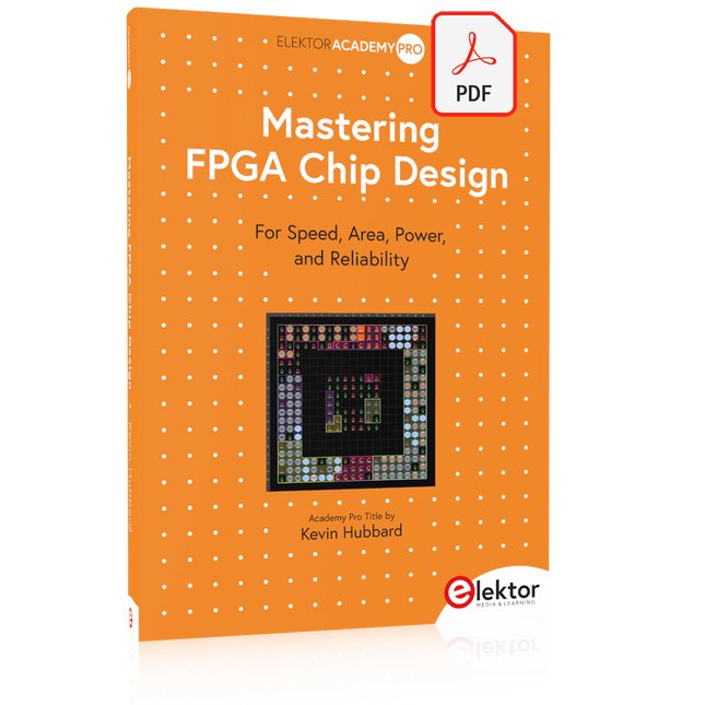
Elektor Digital Mastering FPGA Chip Design (E-book)
For Speed, Area, Power, and Reliability This book teaches the fundamentals of FPGA operation, covering basic CMOS transistor theory to designing digital FPGA chips using LUTs, flip-flops, and embedded memories. Ideal for electrical engineers aiming to design large digital chips using FPGA technology. Discover: The inner workings of FPGA architecture and functionality. Hardware Description Languages (HDL) like Verilog and VHDL. The EDA tool flow for converting HDL source into a functional FPGA chip design. Insider tips for reliable, low power, and high performance FPGA designs. Example designs include: Computer-to-FPGA UART serial communication. An open-source Sump3 logic analyzer implementation. A fully functional graphics controller. What you need: Digilent BASYS3 or similar FPGA eval board with an AMD/Xilinx FPGA. Vivado EDA tool suite (available for download from AMD website free of charge). Project source files available from author’s GitHub site.
€ 32,95
Members: € 29,66
-

OWON OWON DGE3062 2-ch Arbitrary Waveform Generator (60 MHz)
The OWON DGE3062 is a 14-bit function generator with a bandwidth of 60 MHz. It has 5 basic waveforms, 160 built-in arbitrary waveforms and the following comprehensive modulation functions: AM, FM, PM, PWM, FSK, 3FSK, 4FSK, PSK, ASK, BPSK, OSK, DSBAM, QPSK, SUM, sweep, Burst. Features Max. 60 MHz frequency output, 300 MSa/s Sample rate 14 bits Vertical Resolution, 100K Arb waveform length Comprehensive waveform output: 5 basic waveforms, and 160 built-in arbitrary waveforms Comprehensive modulation functions: AM, FM, PM, PWM, FSK, 3FSK, 4FSK, PSK, ASK, BPSK, OSK, DSBAM, QPSK, SUM, sweep, Burst SCPI and LabVIEW supported 3.6 inch LCD (480 x 272 pixels) Specifications Channel 2 Frequency Output 60 MHz Sample Rate 300 MSa/s Vertical Resolution 14 bits Waveform Standard Waveform Sine, square, pulse, ramp, noise Arbitrary Waveform Exponential rise, exponential fall, sin(x)/x, step wave, and others, total 160 built-in waveforms Frequency (resolution 1 μHz) Sine 1 μHz-60 MHz Square 1 μHz ~ 20 MHz Pulse 1 μHz ~ 20 MHz Ramp 1 μHz ~ 2 MHz Noise 20 MHz (-3 dB, typical) Arbitrary Waveform 1 μHz ~10 MHz Arbitrary Waveform Length 2 points – 100K points Sample Rate 300 MSa/s Amplitude Into 50Ω load 1mVpp ~ 10Vpp (≤10Hz), 1mVpp ~ 5Vpp (≤60 MHz) DC Offset Range (AD+DC ±(10 Vpk – Amplitude Vpp/2) high resistance±(5 Vpk – Amplitude Vpp/2) 50 Ω DC offset resolution 1 mV or 4 digits Load Impedance 50 Ω (typical) DC offset Accuracy ±(1% of |setting| + 1 mV + amplitude Vpp * 0.5%) Modulation Type AM,FM, PM, PWM, FSK, 3FSK, 4FSK, PSK, ASK, BPSK, OSK, DSB-AM, QPSK, SUM, Sweep, Burst Frequency Counter Function Frequency, period Frequency Range 100 MHz ~ 100 MHz Frequency Resolution 6 digits Input/Output Display 3.6” LCD Input mode External modulation input, external trigger input, external reference clock input/output Communication Interface USB Host, USB Device Mechanical specifications Dimensions (W x H x D) 200 x 92 x 157 mm Weight 0.8 kg Included 1x OWÒN DGE3062 Arbitrary Waveform Generator 1x Power Cord 1x Quick Guide 1x USB Cable 1x Q9 Cable 1x BNC to Alligator Clip Downloads Quick Guide Manual Software
€ 212,50
-
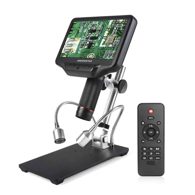
Andonstar Andonstar AD407 7" HDMI Digital Microscope
Examine your circuits with high precision and solder even the smallest SMDs and elements without any hassle. Features Multifunctional HDMI Digital Microscope features Full HD, comfortable headroom, improved ergonomy, multiple output signals with different resolutions. Tilt angle of the wide LCD monitor is adjustable. Comes with remote control. Can be used as stand-alone. Specifications Screen size 7 inch (17.8 cm) Image sensor 4 MP Video output UHD 2880x2160 (24fps)FHD 1920x1080 (60fps/30fps)HD 1280x720 (120fps) Video format MP4 Magnification Up to 270 times (27 inch HDMI monitor) Photo resolution Max. 12 MP (4032x3024) Photo format JPG Focus range Min. 5 cm Frame rate Max. 120fps (under 600 Lux Brightness & HDP120) Video interface HDMI Storage microSD card (up to 32 GB) Power source 5 V DC Light source 2 LEDs with the stand Stand size 20 x 12 x 19 cm Included 1x Andonstar AD407 Digital Microscope 1x Metal stand with 2 LEDs 1x Optical bracket 1x UV filter 1x IR remote 1x Switch cable 1x Power adapter 1x HDMI cable 2x Screws 1x Screwdriver 1x User manual Downloads Manual Model Comparison AD407 AD407 Pro AD409 AD409 Pro-ES Screen size 7 inch (17.8 cm) 7 inch (17.8 cm) 10.1 inch (25.7 cm) 10.1 inch (25.7 cm) Image sensor 4 MP 4 MP 4 MP 4 MP Video output 2160p 2160p 2160p 2160p Interfaces HDMI HDMI USB, HDMI, WiFi USB, HDMI, WiFi Video format MP4 MP4 MP4 MP4 Magnification Up to 270x Up to 270x Up to 300x Up to 300x Photo resolution Max. 4032x3024 Max. 4032x3024 Max. 4032x3024 Max. 4032x3024 Photo format JPG JPG JPG JPG Focus distance Min. 5 cm Min. 5 cm Min. 5 cm Min. 5 cm Frame rate Max. 120f/s Max. 120f/s Max. 120f/s Max. 120f/s Storage microSD card microSD card microSD card microSD card PC support No No Windows Windows Mobile connection No No WiFi + Measurement WiFi + Measurement Power source 5 V DC 5 V DC 5 V DC 5 V DC Light source 2 LEDs with the stand 2 LEDs with the stand 2 LEDs with the stand 2 LEDs with the stand Endoscope No No No Yes Stand size 20 x 12 x 19 cm 20 x 18 x 32 cm 18 x 20 x 30 cm 18 x 20 x 32 cm Weight 1.6 kg 2.1 kg 2.2 kg 2.5 kg
€ 185,13
-

Elektor Digital Meten en regelen via Android (E-book)
Hebt u altijd al uw elektronicaproject willen aansturen vanuiteen kleurrijke app op een Android smartphone of tablet? Dat is mogelijk met het in dit boek beschreven Android I/O-board. Met de bijbehorende software-library kunt u in Android Studio eenvoudig zelf een app programmeren die dit mogelijk maakt. Het Android I/O-board (los verkrijgbaar, wordt niet met boek meegeleverd!) bezit 22 pennen die u vanuit een app kunt aansturen als digitale I/O, ADC, PWM, touch-sensing en counter. Het Android I/O-board kan met de Android smartphone communiceren via Bluetooth, WiFi of USB. Het board is ook als datalogger te gebruiken. Kortom, dit is een veelzijdig board dat in ieder project past. Dit boek beschrijft stap voor stap hoe u uw project tot een succes kunt maken. Het boek behandelt gestructureerd de volgende onderwerpen: Een snelle handleiding hoe u uw Android I/O-board up and running krijgt. Een uitleg van alle mogelijkheden van het Android I/Oboard, met uitgebreide voorbeelden bij de verschillende opties. Een stap-voor-stap handleiding hoe u een app kunt programmeren in Android Studio. Een beschrijving van de firmware op het Android I/O-board en hoe u dit zelf met MPLAB-X kunt aanpassen. Voorbeeld-projecten om inspiratie op te doen hoe u uw eigen project kunt aansturen met het Android I/O-board.
€ 34,95
Members: € 31,46
-

Seeed Studio Seeed Studio RF Explorer 3G Combo Spectrum Analyzer
The Seeed Studio RF Explorer 3G Combo is a handheld digital spectrum analyzer and an affordable tool for working across a wide range of popular frequency bands. It is based on a highly integrated frequency synthesizer and a double-balanced mixer, providing high performance, compact dimensions, low power consumption, and excellent value. Designed for both indoor and outdoor use, the RF Explorer 3G Combo can also be connected to a PC via a standard Mini-USB 2.0 connector for additional functionality. This model combines a WSUB1G base unit with an RFEMWSUB3G expansion module, supplied fully assembled and tested. It features two SMA connectors and includes two antennas: a dual-band 144/430 MHz telescopic antenna for sub-GHz frequencies and a helical whip antenna for the 2.4 GHz band. Additional frequency-specific antennas may be required for optimal performance in certain supported frequency ranges. This combination provides the wide frequency coverage of the WSUB3G module together with the high sensitivity and fast response of the WSUB1G unit in the commonly used sub-1 GHz frequency range. Features Pocket size and light weight Solid aluminum metal case Includes a transport EVA carry case for RF Explorer Spectrum Analyzer mode with Peak Max and Hold, Normal, Overwrite and Averaging modes Lifetime free firmware upgrades available, open to community requested features High capacity Lipo for 16+ hours of continuous run, rechargeable by USB Windows PC client Open Source Can be extended with internal Expansion Modules for additional band and functionality Wide band coverage to all popular RF frequencies, starting at 15 MHz and going up to 2.7 GHz. This includes very interesting frequency areas such as 2 m HAM radio, all VHF and UHF, FM radio, GPS, WiFi and WiMax, Bluetooth, etc. Firmware: RF Explorer 3G Combo is delivered with upgraded firmware v1.09. Note some of the features and operation accuracy will be improved in upcoming free firmware revisions. Specifications Battery Lithium Cells / Batteries contained in equipment UN3481 - PI967 Frequency band 15-2700 MHz Frequency span 112 KHz - 600 MHz Graphics LCD 128 x 64 pixels, great visibility outdoors PC Windows client Supports Windows (32 and 64 bits) Backlight For great indoor visibility 2 standard SMA 50 ohms connector, One for Sub-GHz wideband Nagoya NA-773 telescopic antenna included and another 2.4 GHz one for 15-2700 MHz band with helical antenna included. Amplitude resolution 0.5 dBm Dynamic range Left SMA port (WSUB1G) -115 dBm to 0 dBm Right SMA port (WSUB3G) -110 dBm to -10 dBm Absolute Max input power Left SMA port (WSUB1G) +5 dBm Right SMA port (WSUB3G) +30 dBm Average noise level (typical) -110 dBm Frequency stability and accuracy (typical) ±10 ppm Amplitude stability and accuracy (typical) ±6 dBm Frequency resolution 1 KHz Resolution bandwidth (RBW) Automatic 3 KHz to 600 KHz Weight 185 g Dimensions 113 x 70 x 25 mm Included Seeed Studio RF Explorer 3G Combo Spectrum Analyzer Nagoya NA-773 wideband telescopic antenna 2.4 GHz band antenna EVA Case Documentation For more info and to get started with your RF Explorer, visit the start page. For questions and support, please visit https://support.rf-explorer.com
€ 279,95
-

Elektor Digital FreeRTOS for ESP32-Arduino (E-book)
Practical Multitasking Fundamentals Programming embedded systems is difficult because of resource constraints and limited debugging facilities. Why develop your own Real-Time Operating System (RTOS) as well as your application when the proven FreeRTOS software is freely available? Why not start with a validated foundation? Every software developer knows that you must divide a difficult problem into smaller ones to conquer it. Using separate preemptive tasks and FreeRTOS communication mechanisms, a clean separation of functions is achieved within the entire application. This results in safe and maintainable designs. Practicing engineers and students alike can use this book and the ESP32 Arduino environment to wade into FreeRTOS concepts at a comfortable pace. The well-organized text enables you to master each concept before starting the next chapter. Practical breadboard experiments and schematics are included to bring the lessons home. Experience is the best teacher. Each chapter includes exercises to test your knowledge. The coverage of the FreeRTOS Application Programming Interface (API) is complete for the ESP32 Arduino environment. You can apply what you learn to other FreeRTOS environments, including Espressif’s ESP-IDF. The source code is available from GitHub. All of these resources put you in the driver’s seat when it is time to develop your next uber-cool ESP32 project. What you will learn: How preemptive scheduling works within FreeRTOS The Arduino startup “loopTask” Message queues FreeRTOS timers and the IDLE task The semaphore, mutex, and their differences The mailbox and its application Real-time task priorities and its effect Interrupt interaction and use with FreeRTOS Queue sets Notifying tasks with events Event groups Critical sections Task local storage The gatekeeper task
€ 39,95
Members: € 35,96
-

Elektor Digital Arduino in Control (3e versie) E-book
Physical Computing met het Arduino-platform Dit leerboek over het Arduino-platform is uniek en brengt u stap voor stap van beginner tot gevorderde Arduino-gebruiker. Er wordt duidelijk in uitgelegd waarom en waardoor toepassingen werken, ondersteund door gedetailleerde afbeeldingen in kleur. Er is slechts een geringe elektronische basiskennis vereist, omdat de benodigde hardware uitgebreid wordt besproken. Het laatste gedeelte van dit boek bevat een degelijke theoretische verdieping, zodat u een krachtig naslagwerk achter de hand houdt. Er bestond in het Nederlands nog geen lesboek over dit platform. De didactische opbouw is zodanig dat de vereiste abstracte kennis wordt uitgelegd aan de hand van toepasbare en actuele praktijkvoorbeelden. De meeste toepassingen zijn gericht op ‘physical computing’, dat is de interactie tussen sensoren, actoren, elektronica en software. Hierdoor is het boek ook geschikt voor technisch beroepsonderwijs, o.a. voor de richting mechatronica. De opbouw van het boek is als volgt: Algemene introductie microcontrollers. Informatie over het Arduino-platform. Oefeningen met uitleg aan de hand van 21 voorbeelden. Praktijkvoorbeelden met uitleg aan de hand van 5 voorbeelden. Theoretische verdieping van de software en hardware. Praktische elektronicaschema´s. Alle software-voorbeelden in het boek zijn als download beschikbaar.
€ 34,95
Members: € 31,46
-

Elektor Digital Elektor Circuit Special 2024 PDF (DE)
Diese Ausgabe steht allen GOLD- und GREEN-Mitgliedern auf der ElektorMagazine-Website zum Download bereit! Sie sind noch kein Mitglied? Hier klicken! Digitale Last für HochstromtestsVon der Notwendigkeit zur Innovation GesangsentfernerInstant-Karaoke-Schaltung Audio-Eingangswahlschalter mit VerstärkungseinstellungSchaltet von Mikrofon- auf Line-Eingänge um Ladeschaltung für LIR2032Optimierte Ladung = längere Haltbarkeit Touch-Sensing leicht gemachtEin DIY-Leitfaden für jeden Mikrocontroller Universeller Infrarot-FernschalterEin neues Leben für alte Fernbedienungen Mikrocontroller-gesteuerte MuhdoseBovine Klänge mit einem Mikrocontroller erzeugen USB-Batterieschnittstelle Stromversorgung von Low-Power-Geräten mit PowerbanksEine Stay-Alive-Lösung Kleiner Klasse-A-Audioverstärker mit StromausgangLautsprecher mit Strom statt mit Spannung ansteuern Pseudosymmetrisches ModulHohes Gleichtaktunterdrückungsverhältnis trotz asymmetrischen Audioverbindungen Automatisches Ladegerät für Ni-MH-ZellenFüllen Sie alle Ihre Akkupacks in einem Rutsch auf! Sicherheit durch thyristor-basierte Strombegrenzung Fingerabdruck-Sensor-SchalterEin nützliches Gerät zum Identitätsnachweis 3-A-GleichspannungswandlerBessere Nutzung Ihrer Festspannungsquellen Innovationen aus dem Arduino-Project-HubNeue Projekte aus der Community Fernkontrolle eines BoilersSpannungs- und Stromdetektion für Netzspannungsleitungen Abschwächer für AudiosignaleTeil 1. Einstellbar über Jumper Autobatterie-Ladegerät aufgemotztTeil 1. Wiederverwenden statt wegwerfen! Eine Platine für „The Blue One“Platine für Alps-Motorpotentiometer mit Rückmeldung 50-Hz-Referenz aus 60-Hz-NetzspannungWie man 50-Hz-Elektronik in 60-Hz-Umgebungen verwendet Digitale IsolatorenGalvanische Trennung einfach realisieren Kompakter 12-W-Hi-Fi-MonoverstärkerKlein, aber leistungsstark LM386-Rampengenerator DrehstromgeneratorMit Raspberry Pi Pico Türöffner für musikalisch Begabte Elektor-Klassiker: Surf-SynthesizerMeereswassersporthintergrundgeräuschgenerator (Mwsh3g) Autobatterie-Ladegerät aufgemotztTeil 2. Ladesteuerung analog und digital LampenstromüberwachungMit Raspberry Pi Pico Infrarot-Telegraphie Fnirsi SWM-10Reparatur von Batteriepacks mit tragbarem intelligentem Punktschweißgerät Stereo-Audio-Codec für ESP32 und Co.Keine Angst vor Audio-Messtechnik Die Kunst des LötensLötzinn-Techniken für einwandfreie Verbindungen Abschwächer für AudiosignaleTeil 2. Umschalten per Relais USB-C-PowerStrom aus USB-C-Netzteilen beziehen Drei Schaltungen mit zwei und drei Zähler-ICs4017-ICs im Zusammenspiel Aktive Bauelemente – Die Diode Timer für extrem lange VerzögerungenEinstellen und vergessen! Klinke rein, Klinke rausEine nützlicher Anschluss für Audioschaltungen ESP32 mit nur einer Lithium-Zelle versorgen Hexadoku
€ 11,90
-

Elektor Digital Elektor 11-12/2024 (PDF)
Diese Ausgabe steht allen GOLD- und GREEN-Mitgliedern auf der ElektorMagazine-Website zum Download bereit! Sie sind noch kein Mitglied? Hier klicken! Audio-DSP-FX-Prozessor-BoardTeil 1: Eigenschaften und Design 50 Jahre Elektor in englischer Sprache KiCad 8Neue und aktualisierte Funktionen MultiCalculator-KitEin Elektronikrechner-Bausatz von Elektor mit Arduino Preiswerte GNSS-RTK-SystemeFür zentimetergenaue Positionsbestimmung Platinenlayout und SicherheitTipps für sichere und langlebige Leiterplatten Opamp-TesterFür Audio- und andere Anwendungen Projekt-Update #4 : Energiemessgerät mit ESP32Energieüberwachung mit MQTT Echtzeit-Spektrumanalyzer mit Waveguide-Technologie und Multi-Schnittstellen-PCsAaronia etabliert neues Produktsegment und präsentiert erste Prototypen auf der electronica in München electronica 2024Highspeed und robuste Board-to Board Steckverbinder InduktivitätenSpulen und Ferrite anwendungsorientiert selektieren EMI-Abschirmung zur Einhaltung der elektromagnetischen Konformität Das ultimative Werkzeug für jeden Elektronik-EnthusiastenUnendliche Möglichkeiten mit Red Pitaya und 1.000+ Click Boards™ Die 100 % durchgängige Flussmittelseele Siglent stellt seine neue Vektornetzwerkanalysator-Plattform SNA6000A vor HDI der MittelklasseEin neuer ökonomischer PCB Pooling Service für hochpolige BGAs Ferngesteuerte IoT-EntwicklungDie einzige Lösung für Fernunterricht und Entwicklung in der Embedded-Industrie Herausforderungen der DFM-Analyse für Flex- und Rigid-Flex-Design Aus dem Leben gegriffenMikrotechnophobie Feliz Natal: 3D-WeihnachtsbaumEine 3D-Platine mit preiswertem 32-Bit-Mikrocontroller Aller Anfang......muss nicht schwer sein: Weiter geht es mit den Opamps! Ein autonomer SensorknotenProjekt-Update #1: Reduzierung der Leerlauf-Stromaufnahme mit externer RTC mit Leistungsschalter 2024: Eine Odyssee in die KIEin Blick zurück in die Zukunft LED-Displays mit dem MAX7219Ein praktischer Ansatz für einen großartigen Chip Projekt 2.0Korrekturen, Updates und Leserbriefe VibroTactile-HandschuheEin Durchbruch für Parkinson-Patienten?
€ 11,90


