
Search results for "youloop or portable or passive or magnetic or loop or antenna or for or hf or and or vhf"
-

OWON OWON P4603 DC Power Supply (180 W)
This OWON DC Power Supply has a small body and is easy to carry due to its light weight. Featuring a 3.7" TFT LCD display, it has a maximum output power of 180 W and a resolution of 1 mV/1 mA. Features Channel Single Channel Output Total Output Power 180 W Channel Output 0 - 60 V / 0 - 3 A × 1-CH Display 3.7' color LCD display Dimension 117 mm(L) × 194 mm(H) × 295 mm(D) Weight Approx. 5.8 kg Interface RS232 Specifications Rated Output (0 ℃ - 40 ℃) Voltage 0 - 60 V Current 3 A Load Regulation Voltage ≤ 0.01% + 3 mV Current ≤ 0.01% + 3 mA Power Regulation Voltage ≤ 0.01% + 3 mV Current ≤ 0.01% + 3 mA Setting Resolution Voltage 1 mV Current 1 mA Readback Resolution Voltage 1 mV Current 1 mA Setpoint accuracy (within 12 months) (25 ℃ ± 5 ℃) Voltage ≤ 0.03% + 10 mV Current ≤ 0.1% + 5 mA Readback Resolution (25 ℃ ± 5 ℃) Voltage ≤ 0.03% + 10 mV Current ≤ 0.1% + 5 mA Ripple/Noise (20 Hz - 20 MHz) Voltage (Vp-p) ≤ 4 mVp-p Voltage (Vrms) ≤ 1 mVrms Current (rms) ≤ 4 mArms Output temperature coefficient(0 ℃ - 40 ℃) Voltage ≤ 0.03% + 10 mV Current ≤ 0.1% + 5 mA Readback temperature coefficient Voltage ≤ 0.03% + 10 mV Current ≤ 0.1% + 5 mA Response Time 100 μs Storage 5 groups of data Working Temperature 0 - 40 ℃
€ 164,57
-

Elektor Publishing Grundlagen der Elektrotechnik
Dieses Fachbuch führt Studenten, Schüler und Selbststudierende in die wichtigsten Grundlagen der Elektrotechnik ein. Es werden die Gebiete der Gleichstromtechnik, des elektrischen und magnetischen Feldes sowie der Wechselstromtechnik, des Kondensators und der Spulen in einem Band zusammenhängend und übersichtlich dargestellt. Daran schließt sich die Beschreibung des elektrischen und magnetischen Feldes an. Zur Erzielung einer optimalen Verständlichkeit erfolgt die Darbietung des Stoffes nach dem Grundsatz, den Leser von einfachen Sachverhalten schrittweise zu komplexeren Problemstellungen zu führen. Zusätzlich sind den einzelnen Abschnitten Aufgaben mit ausführlichen Lösungswegen zugeordnet. Sie sind zum Erfassen der Gedankengänge von besonderer Bedeutung. Das Buch ist in acht Kapiteln unterteilt: Physikalische Größen und ihre Einheiten Elektrotechnische Größen im Gleichstromkreis Einfacher Stromkreis Erweiterter Strombereich Messgeräte für die Grundschaltungen der Elektronik Kondensator Spulen, Transformatoren, Relais und Lautsprecher Zusammengesetzte Wechselstromkreise Die Aufgaben sind zum großen Teil der elektrotechnischen Praxis entnommen und werden mit steigendem Schwierigkeitsgrad angeboten, so dass für jede Vorbildungsstufe geeigneter Übungsstoff zu finden ist. Der Inhalt ist als Hilfsmittel für den Unterricht und das Selbststudium bestimmt, sie kann auch dem Praktiker beim Auffrischen seiner Kenntnisse und zur Förderung seiner Rechenfertigkeit nützlich sein. Mit diesem Buch gibt der Autor sein gesamtes Wissen, das er sich im Laufe der Zeit in der Industrie und dem Unterricht an einer Technikerschule angeeignet hat, an den Leser weiter.
€ 39,80
Best Price
-
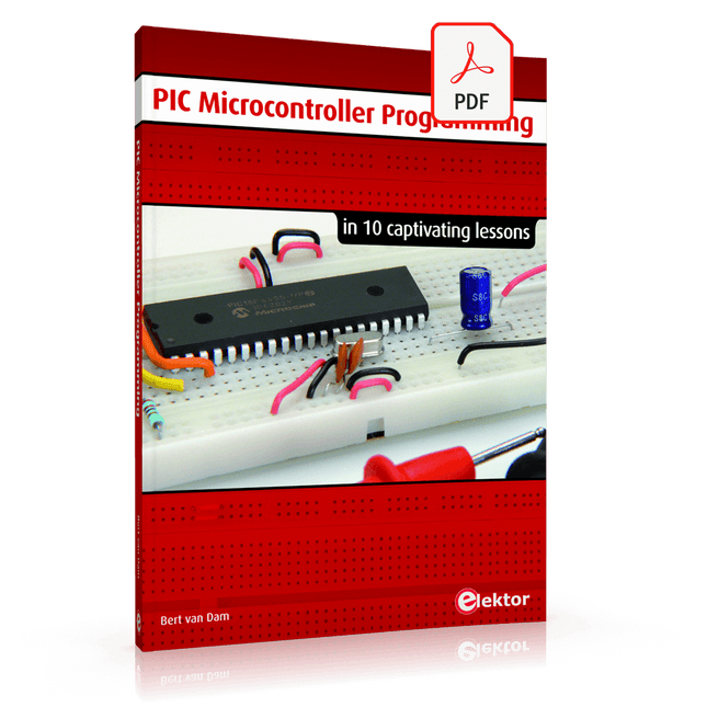
Elektor Digital PIC Microcontroller Programming (E-book)
in 10 captivating lessons Using the lessons in this book you learn how to program a microcontroller. You’ll be using JAL, a free but extremely powerful programming language for PIC microcontrollers, which enjoys great popularity in the hobby world. Starting out from scratch virtually, you slowly build up the knowledge. No previous knowledge is needed: anyone can get started with this book. Assuming you have absorbed all lessons – meaning you have actually completed all the exercises – you should be confident to write PIC microcontroller programs, as well as read and understand programs written by other people. JAL commands You learn the function of JAL commands such as include, pin, delay, forever loop, while loop, case, exit loop, repeat until, if then, as well as the use of functions, procedures and timer- and port interrupts. JAL programs You make an LED blink, build a time switch, measure a potentiometer’s wiper position, produce sounds, suppress contact bounce, and control the brightness of an LED. And of course you learn to debug, meaning: how to spot and fix errors in your programs. Hardware You learn to recognize various components including the PIC microcontroller, potentiometer and quartz crystal, and how to wire up a PIC microcontroller and effectively link it to your PC. A breadboard is used for the purpose, allowing you to easily modify the component arrangement for further experimenting. The companion software with this book can be downloaded free of charge, including the JAL programming language. In addition, you may order a kit of parts so you don’t have to go shopping for the required components. Especially for a beginner, this is the easiest way to start with this unique pastime. Having finished this book does not mean you are through with your pastime. You can get your hands dirty again, and if desired use other books packed with fun projects using the JAL programming language. More information may be found at the end of the lessons in the chapter "Done! What’s next?""
€ 29,95
Members: € 26,96
-
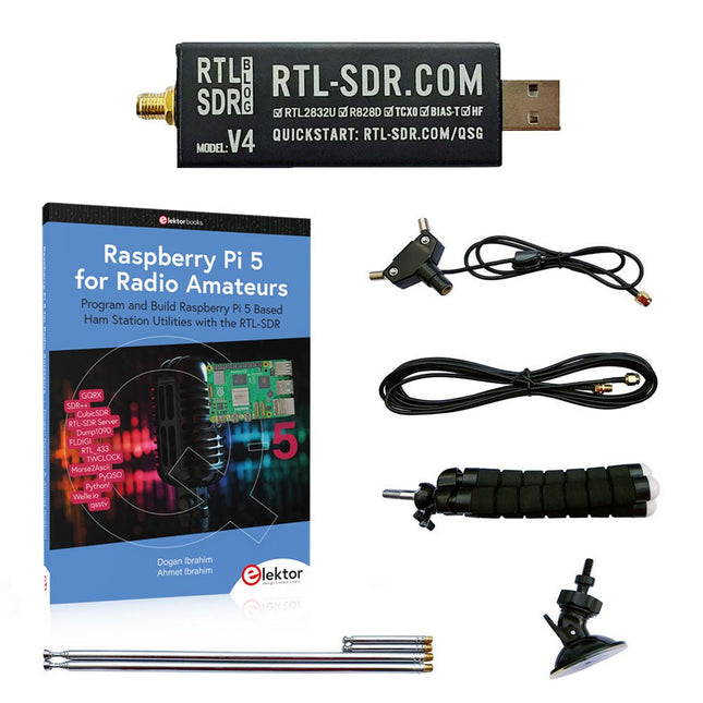
Elektor Bundles Raspberry Pi 5 RTL-SDR V4 (Bundle)
Program and build Raspberry Pi based ham station utilities, tools, and instruments The improved RTL-SDR V4 allows you to receive radio signals between 500 kHz and 1.75 GHz from stations utilizing different bands including MW/SW/LW broadcast, ham radio, utility, air traffic control, PMR, SRD, ISM, CB, weather satellite, and radio astronomy. The book Raspberry Pi 5 for Radio Amateurs gives extensive coverage of deploying the RTL-SDR kit through the use of a Raspberry Pi 5. This bundle contains: RTL-SDR V4 (incl. Dipole Antenna Kit) (normal price: €75) Raspberry Pi 5 for Radio Amateurs (normal price: €40) RTL-SDR V4 (Software Defined Radio) with Dipole Antenna Kit RTL-SDR is an affordable dongle that can be used as a computer-based radio scanner for receiving live radio signals between 500 kHz and 1.75 GHz in your area. The RTL-SDR V4 offers several improvements over generic brands including use of the R828D tuner chip, triplexed input filter, notch filter, improved component tolerances, a 1 PPM temperature compensated oscillator (TCXO), SMA F connector, aluminium case with passive cooling, bias tee circuit, improved power supply, and a built in HF upconverter. RTL-SDR V4 comes with the portable dipole antenna kit. It is great for beginners as it allows for terrestrial and satellite reception and easy to mount outdoors and designed for portable and temporary outside usage. Features Improved HF reception: V4 now uses a built-in upconverter instead of using a direct sampling circuit. This means no more Nyquist folding of signals around 14.4 MHz, improved sensitivity, and adjustable gain on HF. Like the V3, the lower tuning range remains at 500 kHz and very strong reception may still require front end attenuation/filtering. Improved filtering: The V4 makes use of the R828D tuner chip, which has three inputs. The SMA input has been triplexed input into 3 bands: HF, VHF and UHF. This provides some isolation between the 3 bands, meaning out of band interference from strong broadcast stations is less likely to cause desensitization or imaging. Improved filtering x2: In addition to the triplexing, the open drain pin on the R828D can be also used, which allows to add simple notch filters for common interference bands such as broadcast AM, broadcast FM and the DAB bands. These only attenuate by a few dB, but may still help. Improved phase noise on strong signals: Due to an improved power supply design, phase noise from power supply noise has been significantly reduced. Less heat: Another advantage of the improved power supply is low power consumption and less heat generation compared to the V3. Included 1x RTL-SDR V4 dongle (R828D RTL2832U 1PPM TCXO SMA) 2x 23 cm to 1 m telescopic antenna 2x 5 cm to 13 cm telescopic antenna 1x Dipole antenna base with 60 cm RG174 1x 3 m RG174 extension cable 1x Flexible tripod mount 1x Suction cup mount Downloads Datasheet User Guide Quick Start Guide SDR# User Guide Dipole Antenna Guide Book: Raspberry Pi 5 for Radio Amateurs The RTL-SDR devices (V3 and V4) have gained popularity among radio amateurs because of their very low cost and rich features. A basic system may consist of a USB based RTL-SDR device (dongle) with a suitable antenna, a Raspberry Pi 5 computer, a USB based external audio input-output adapter, and software installed on the Raspberry Pi 5 computer. With such a modest setup, it is possible to receive signals from around 24 MHz to over 1.7 GHz. This book is aimed at amateur radio enthusiasts and electronic engineering students, as well as at anyone interested in learning to use the Raspberry Pi 5 to build electronic projects. The book is suitable for both beginners through experienced readers. Some knowledge of the Python programming language is required to understand and eventually modify the projects given in the book. A block diagram, a circuit diagram, and a complete Python program listing is given for each project, alongside a comprehensive description. The following popular RTL-SDR programs are discussed in detail, aided by step-by-step installation guides for practical use on a Raspberry Pi 5: SimpleFM GQRX SDR++ CubicSDR RTL-SDR Server Dump1090 FLDIGI Quick RTL_433 aldo xcwcp GPredict TWCLOCK CQRLOG klog Morse2Ascii PyQSO Welle.io Ham Clock CHIRP xastir qsstv flrig XyGrib FreeDV Qtel (EchoLink) XDX (DX-Cluster) WSJT-X The application of the Python programming language on the latest Raspberry Pi 5 platform precludes the use of the programs in the book from working on older versions of Raspberry Pi computers.
-

Elektor Labs Elektor Dual DC LISN (150 kHz – 200 MHz)
Measuring conducted emission is the simplest and most affordable method of getting some indication of whether a design can meet EMI/EMC requirements. A Line Impedance Stabilization Network (LISN) is an indispensable part of an EMC pre-compliance test setup. In cooperation with Würth Elektronik, Elektor has developed a 5 µH, 50 Ω Dual DC LISN that supports voltages up to 60 V and currents up to 10 A. The instrument measures RF interferences on both channels (the power supply) by means of 5-μH blocking inductances. The internal 10-dB attenuation network – one in each channel – contains a 3rd-order high-pass filter with a cutoff frequency of 9 kHz to protect the input of instruments like a spectrum analyzer from potentially harmful DC voltages or low frequencies coming from the EUT (Equipment Under Test). Specifications RF path Channels 2 (with clamping diodes) Bandwidth 150 kHz – 200 MHz Inductance 5 μH || 50 Ω Internal attenuation 10 dB Connectors SMA DC path Max. current < 10 ADC Max. voltage < 60 VDC DC resistance < 2 x 70 mΩ PCB size 94.2 x 57.4 mm Connectors 4-mm banana Hammond enclosure Type 1590N Dimensions 121 x 66 x 40 mm Included 1x 4-layer PCB with all SMT parts fitted 1x pre-drilled enclosure with ready-printed front panel layout 5x gold-plated, insulated, 4-mm banana sockets, rated for 24 A, 1 kV 1x Hammond enclosure 1590N1, Aluminum (Die-Cast Alloy) More Info Project on Elektor Labs: Dual DC LISN for EMC pre-compliance testing Elektor 9-10/2021: EMC Pre-Compliance Test for Your DC-Powered Project (Part 1) Elektor 11-12/2021: EMC Pre-Compliance Test for Your DC-Powered Project (Part 2)


