
Search results for "voltera OR v OR one OR desktop OR pcb OR printer"
-

Elektor Bundles Logic Analyzer im Einsatz (Bundle)
Buch: Logic Analyzer im Einsatz Schritt-für-Schritt-Anleitungen führen Sie in die Analyse moderner Protokolle von I²C, SPI, UART, RS-232, NeoPixel, WS28xx, HD44780 und 1-Wire ein. Anhand von zahlreichen Experimentierschaltungen mit dem Raspberry Pi Pico, Arduino Uno und dem Bus Pirate üben Sie die praxisnahe Anwendung gängiger USB-Logikanalysatoren ein. Alle in diesem Buch vorgestellten Experimentierschaltungen wurden vollständig getestet und sind funktionsfähig. Die notwendigen Programmlistings sind enthalten, es sind keine besonderen Programmier- oder Elektronikkenntnisse für diese Schaltungen notwendig. Es werden die Programmiersprachen MicroPython und C mit den Entwicklungsumgebungen Thonny und Arduino IDE eingesetzt. Dieses Buch verwendet mehrere Modelle flexibler und weit verbreiteter USB-Logikanalysatoren und zeigt die Stärken und Schwächen jeder Preisklasse. Sie werden kennenlernen, welche Kriterien für Ihre Arbeit wichtig sind und in der Lage sein, das für Sie passende Gerät zu finden. Egal ob Arduino, Raspberry Pi oder Raspberry Pi Pico: Die abgebildeten Beispielschaltungen ermöglichen einen schnellen Start in die Protokollanalyse und können auch als Grundlage für eigene weitere Experimente dienen. Sie werden alle wichtigen Begriffe und Zusammenhänge kennenlernen, eigene Experimente durchführen, selbstständig Protokolle analysieren und nach der Lektüre dieses Buches – im Bereich der digitalen Signale und Protokolle – ein umfassendes Wissen aufgebaut haben. USB Logic Analyzer (8 Kanäle, 24 MHz) Dieser USB Logic Analyzer ist ein 8-Kanal-Logikanalysator, bei dem jeder Eingang doppelt für die analoge Datenaufzeichnung dient. Es eignet sich perfekt zum Debuggen und Analysieren von Signalen wie I²C, UART, SPI, CAN und 1-Wire. Dabei wird ein digitaler Eingang, der mit einem zu testenden Gerät (DUT) verbunden ist, mit einer hohen Abtastrate abgetastet. Die Verbindung zum PC erfolgt via USB. Technische Daten Kanäle 8 digitale Kanäle Maximale Abtastrate 24 MHz Maximale Eingangsspannung 0 V ~ 5 V Betriebstemperatur 0°C ~ 70°C Eingangsimpedanz 1 MΩ || 10 pF Unterstützte Protokolle I²C, SPI, UART, CAN, 1-Wire etc. PC-Verbindung USB Abmessungen 55 x 28 x 14 mm Downloads Software Dieses Bundle enthält: Buch: Logic Analyzer im Einsatz (Einzelpreis: 40 €) USB Logic Analyzer (8 Kanäle, 24 MHz) (Einzelpreis: 20 €) USB-Kabel Jumper Wire Ribbon Kabel
€ 59,95€ 49,95Best Price
-

Red Pitaya Red Pitaya STEMlab 125-14 PRO Gen 2 Starter Kit (incl. Book)
This bundle includes the Red Pitaya STEMlab 125-14 PRO Gen 2 Starter Kit and the new book "Experimenting with Red Pitaya STEMlab Gen 2". The Red Pitaya STEMlab 125-14 PRO Gen 2 Starter Kit is a powerful and flexible platform for signal processing, data acquisition, and electronic measurement applications. Designed for engineers, developers, researchers, and educators, this kit provides everything required to start building advanced measurement and control systems. At the core of the kit is the STEMlab 125-14 PRO Gen 2 board, an upgraded and ultra-lightweight development platform. Powered by the Xilinx Zynq-7010 SoC with 512 MB of RAM, it combines FPGA programmability with ARM processing power to enable high-performance instrumentation and custom signal-processing solutions. The board offers 14-bit ADC and DAC resolution, a 125 MS/s sampling rate, an input range of ±20 V, and up to 60 MHz bandwidth. Its improved low-noise analog front-end, USB-C connectivity, and compact design make it suitable for demanding applications such as RF development, radar systems, photonics research, software-defined radio (SDR), and industrial automation. The Starter Kit includes all essential accessories for immediate use: a microSD card with preinstalled operating system, power supply, Ethernet cable for remote access, two 100 MHz oscilloscope probes, and SMA-to-BNC adapters for flexible signal connections. The Red Pitaya STEMlab 125-14 PRO Gen 2 Starter Kit is an excellent platform for rapid prototyping, FPGA development, measurement instrumentation, and advanced electronics experimentation. Features 14-bit ADC and DAC resolution 125 MS/s sampling rate ±20 V input range Up to 60 MHz bandwidth Xilinx Zynq-7010 SoC (FPGA + ARM processor) 512 MB RAM Low-noise analog front- and back-ends Applications RF development and testing Radar and wireless systems Software-defined radio (SDR) Photonics and optical research Industrial automation and control systems Signal analysis and instrumentation Rapid prototyping of electronic measurement systems Specifications Processor Dual-core ARM Cortex-A9 FPGA AMD Xilinx Zynq-7010 SoC RAM 512 MB (4 Gb) Storage microSD card (up to 32 GB) Operating System Linux-based Red Pitaya OS ADC Resolution 14-bit DAC Resolution 14-bit Bandwidth 60 MHz (DC) Sampling Rate 125 MS/s Analog Input Channels 2 Analog Output Channels 2 Input Voltage Range ±1 V (LV) / ±20 V (HV) Input Impedance 1 MΩ / 10 pF Output Voltage Range ±1 V Ethernet 1x Gigabit Ethernet (RJ45) USB 2x USB-C 2.0 (for power and console) Digital I/O 16x GPIO (3.3 V) Communication Interfaces I²C, SPI, UART, CAN Power Supply 5 V/3 A via USB-C Dimensions 106.8 x 60.0 x 17.9 mm Included 1x Red Pitaya STEMlab 125-14 PRO Gen 2 board 2x 100 MHz oscilloscope probes 2x SMA-to-BNC adapters 1x microSD card with preinstalled OS 1x USB-C Power supply 1x Ethernet cable Downloads Documentation Schematics Book: Experimenting with Red Pitaya STEMlab Gen 2 With this new book, Red Pitaya goes beyond a versatile board. It becomes a powerful laboratory instrument for precision measurement, analysis, and control. From the fundamentals of electronic project development, monitoring, control, and design to testing, this book walks you step-by-step through everything you need to know to harness the full potential of Red Pitaya hardware and software. The book presents real-time, FPGA-based projects that are developed on a PC using the Vivado environment, then transferred to the Red Pitaya for execution and testing. You will learn about enhanced performance, expanded I/O capabilities, improved FPGA features, and advanced connectivity options that open up new frontiers for precision measurement, monitoring, and control in your embedded applications. Inside the book you will discover: A deep dive into Red Pitaya architecture and hardware design Electronic experiments using Red Pitaya for measurement and monitoring Hands-on projects using the Python programming language Practical guidance for FPGA programming using Red Pitaya Red Pitaya FPGA projects using the Verilog HDL under Vivado IDE Practical design of electronic projects including measurement and testing Step-by-step examples that bridge theory and real-world implementation Whether you are designing your own electronic circuits, developing signal analysis tools, or creating real-time control or monitoring systems, this book provides you the knowledge and confidence you need to fully learn and customize the Red Pitaya platform.
€ 799,00
Best Price
-

FNIRSI FNIRSI 2D15P (3-in-1) 2-ch Oscilloscope (100 MHz) + Multimeter + Signal Generator
The FNIRSI 2D15P is a compact 3-in-1 test tool combining a 2-channel digital oscilloscope, True RMS multimeter, and waveform generator in one device. With a 4.3" capacitive touchscreen, 100 MHz bandwidth, 500 MSa/s sampling rate, and up to 1,200 fps capture speed, it’s ideal for fast troubleshooting, signal analysis, and electronics testing. Features Dual-Channel Input (100 MHz single-channel, 50 MHz dual-channel operation) Selectable Memory Depths 20 MHz Bandwidth Limit Grayscale & Color Temperature Visualization Math Operations (Add, Subtract, Multiply, Divide, etc.) XY Mode & Infinite Persistence Cursor Function & 13 Auto Measurements Auto / Normal / Single Trigger Modes True RMS Multimeter (19,999 Counts) 10 MHz DDS Signal Generator Specifications General Display 4.3" IPS Capacitive Touchscreen Operation Touch + Knob + Physical Buttons Charging USB-C (12 V/1 A fast charging) Battery 5000 mAh Lithium battery Dimensions 19.6 x 12.9 x 5.7 cm Weight 1.1 kg Oscilloscope Channels 2 Analog Bandwidth 100 MHz Sample Rate 500 MSa/s Memory Depth 10K, 100K, 1M Input Impedance 1 MΩ Timebase Range 5ns - 50s Vertical Sensitivity 10 mV - 10 V/div Max Input Voltage 800 V (x10 Probe) Trigger Mode Auto, Normal, Single Trigger Type Rising, Falling, Both Edges Coupling AC/DC Persistence min / 2s / 5s / 10s / 20s / 50s / ∞ Math Operations Yes Waveform Capture Yes Waveform Export Yes Cursor Measurement Yes Multimeter DC Voltage 1.9999V / 19.999V / 199.99V / 1000V AC Voltage 1.9999V / 19.999V / 199.99V / 750.0V DC Current 19.999mA / 199.99mA / 1.9999A / 9.999A AC Current 19.999mA / 199.99mA / 1.9999A / 9.999A Resistance 19.999MΩ / 1.9999MΩ / 199.99KΩ / 19.999KΩ / 1.9999KΩ / 199.99Ω Capacitance 999.9uF / 99.99uF / 9.999uF / 999.9nF / 99.99nF / 9.999nF / 9.999mF / 99.99mF Diode Yes Continuity Yes Signal Generator Channels 1 Frequency 0–10 MHz Amplitude 0.1–3.0 Vpp Duty Cycle 0–100% Included 1x FNIRSI 2D15P Oscilloscope 2x P6100 Oscilloscope Probes 1x Multimeter Probe 1x Alligator Clip Probe 1x USB Data Cable 1x Manual Downloads Manual Firmware V2.7.0.7
€ 209,00€ 179,95Best Price
-
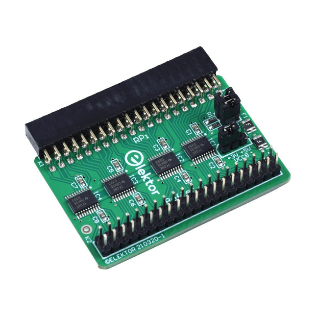
Elektor Labs Elektor Raspberry Pi Buffer Board
When you experiment with the Raspberry Pi on a regular basis and you connect a variety of external hardware to the GPIO port via the header you may well have caused some damage in the past. The Elektor Raspberry Pi Buffer Board is there to prevent this! The board is compatible with Raspberry Pi Zero, Zero 2 (W), 3, 4, 5, 400 and 500. All 26 GPIOs are buffered with bi-directional voltage translators to protect the Raspberry Pi when experimenting with new circuits. The PCB is intended to be inserted in the back of Raspberry Pi 400/500. The connector to connect to the Raspberry Pi is a right angled 40-way receptacle (2x20). The PCB is only a fraction wider. A 40-way flat cable with appropriate 2x20 headers can be connected to the buffer output header to experiment for instance with a circuit on a breadboard or PCB. The circuit uses 4x TXS0108E ICs by Texas Instruments. The PCB can also be put upright on a Raspberry Pi. Downloads Schematics Layout
€ 34,95
Members: € 31,46
-

Elektor Digital Build Your Own Multifunctional 4-Axis CNC Machine (E-book)
Plot, Cut, Drill, Mill and Laser with the Z99 This book covers the construction, hardware, software, and operation of the Z99 – CNC machine. This is a multifunctional 4-axis machine for home construction. The capabilities of the Z99 machine include: large-format schematic plotting PCB plotting with etch-resist pens schematic plotting with conductive-ink pens letter cutting out of vinyl paper cutting PCB/substrate drilling PCB/substrate milling text milling laser engraving laser cutting of solder paste masks By making the support software available as freeware, readers of the book are challenged and encouraged to develop new applications for the Z99. The machine would not be of much use if the user has no option to create suitable files for the designs in mind. A large part of this book is dedicated to creating source files in a variety of freeware software packages, including Inkscape, DesignSpark PCB, KiCad, and FlatCAM. The book is also useful for readers keen to comprehend and then master the basic structure of HPGL, Gerber, Drill, and G-code files, as well as to have a go at deciphering them using software.
€ 29,95
Members: € 26,96
-
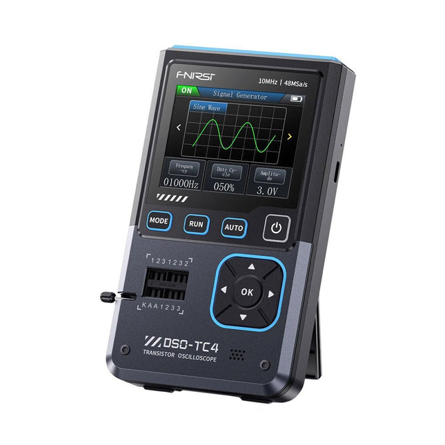
FNIRSI FNIRSI DSO-TC4 (3-in-1) Oscilloscope (10 MHz) + Transistor Tester + Signal Generator
The FNIRDSI DSO-TC4 is a multifunctional transistor oscilloscope that is both comprehensive and practical. It is designed for use in maintenance and R&D applications, integrating an oscilloscope, transistor tester, and signal generator into a single device. Features Equipped with a 2.8-inch TFT color screen for a clear and intuitive display Built-in high-capacity rechargeable lithium battery (1500 mAh) with a standby time of up to 4 hours Compact and lightweight, ideal for mobile use Specifications Oscilloscope Analog Bandwidth 10 MHz Real-Time Sampling Rate 48 MSa/s Input Impedance 1 MΩ Coupling Mode AC/DC Test Voltage Range 1:1 Probe: 80 Vpp (+40 V) 10:1 Probe: 800 Vpp (+400 V) Vertical Sensitivity 10 mV/div~10 V/div (X1 range) Vertical Displacement Adjustable with indication Time Base Range 50ns~20s Trigger Mode Auto/Normal/Single Trigger Type Rising edge, Falling edge Trigger Level Adjustable with indication Waveform Freeze Yes (HOLD function) Automatic Measurement Max, Min, Avg, RMS, Vpp, Frequency, Cycle, Duty Cycle Component Tester Transistor Amplification factor "hfe"; Base-Emitter voltage "Ube", Ic/Ie, Collector-Emitter reverse leakage current "Iceo", Ices, Forward voltage drop of protection diode "Uf" Diode Forward voltage drop <5 V (Forward voltage drop, Junction capacitance, Reverse leakage current) Zener Diode 0.01~32 V Reverse Breakdown Voltage (K-A-A Test Area) Field-Effect Transistor (FET) JFET: Gate capacitance "Cg", Drain current Id under "Vgs", Forward voltage drop of protection diode "Uf" IGBT: Drain current Id under Vgs, Forward voltage drop of protection diode Uf MIOSTET: Threshold voltage "Vt", Gate capacitance "Cg", Drain-Source resistance "Rds", Forward voltage drop of protection diode "Uf" Unidirectional SCR Trigger voltage <5V, Gate level (Gate voltage) Bidirectional SCR Trigger current <6mA (Gate voltage) Capacitor 25pF~100mF, Capacitance value, Loss factor "Vloss" Resistor 0.01Ω~50MΩ Inductor 10μH~1000μH, DC resistance DS18B20 Temperature sensor, Pins: GND, DQ, VDD DHT11 Temperature and humidity sensor, Pins: VDD, DATA, GND Signal Generator Output Waveform Supports 13 waveform outputs Waveform Frequency 0-50 KHz Square Wave Duty Cycle 0-100% Waveform Amplitude 0.1-3.0 V General Display 2.8-inch TFT color screen Backlight Brightness adjustable Power Supply USB-C (5 V/1 A) Battery 3.7 V/1500 mAh Languages English, German, Spanish, Portuguese, Russian, Chinese, Japanese, Korean Dimensions 90 x 142 x 27.5 mm Weight 186 g Included 1x FNIRSI DSO-TC4 (3-in-1) Oscilloscope (10 MHz) 1x P6100 Oscilloscope probes (10X) 1x Alligator clip probe 3x Test hooks 1x Adapter 1x USB-C charging cable 1x Manual Downloads Manual Firmware V0.0.7 (+V1.0.9)
€ 89,95€ 74,95Best Price
-
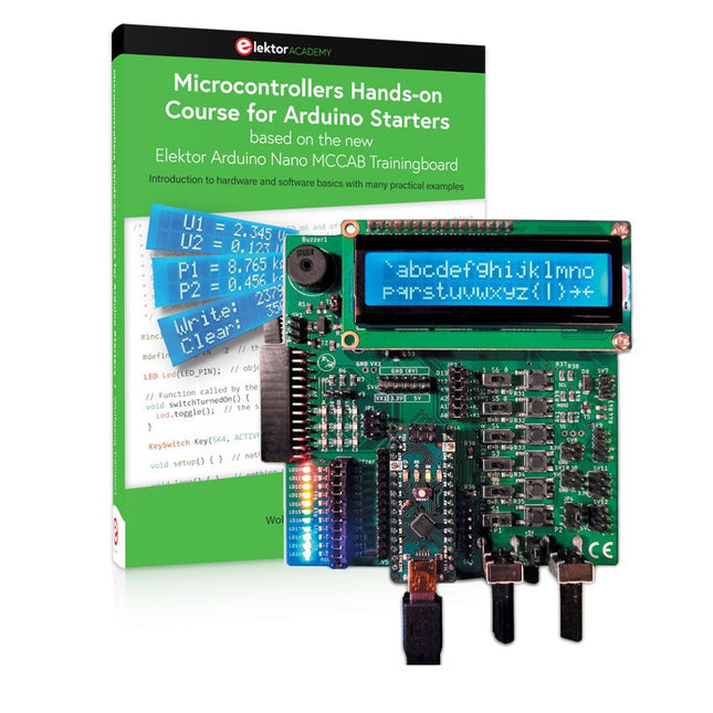
Elektor Bundles Microcontrollers Hands-on Course for Arduino Starters (Bundle)
Realize your own projects with the Elektor Arduino Nano MCCAB Training Board The microcontroller is probably the most fascinating subfield of electronics. Due to the multitude of functions, it combines on its chip, it is a universal multi-tool for developers to realize their projects. Practically every device of daily use today is controlled by a microcontroller. However, for an electronic layman, realizing his own ideas with a microcontroller has so far remained a pipe dream due to its complexity. The Arduino concept has largely simplified the use of microcontrollers, so that now even laymen can realize their own electronics ideas with a microcontroller. Book & Hardware in the Bundle: 'Learning by Doing' This book, which is included in the bundle, shows how you can realize your own projects with a microcontroller even without much experience in electronics and programming languages. It is a microcontrollers hands-on course for starters, because after an overview of the internals of the microcontroller and an introduction to the programming language C, the focus of the course is on the practical exercises. The reader acquires the necessary knowledge by 'learning by doing': in the extensive practical section with 12 projects and 46 exercises, what is learned in the front part of the book is underpinned with many examples. The exercises are structured in such a way that the user is given a task to solve using the knowledge built up in the theoretical part of the book. Each exercise is followed by a sample solution that is explained and commented on in detail, which helps the user to solve problems and compare it with his own solution. Arduino IDE The Arduino IDE is a software development environment that can be downloaded for free to your own PC and that contains the entire software package needed for your own microcontroller projects. You write your programs ('apps') with the IDE’s editor in the C programming language. You translate them into the bits and bytes that the microcontroller understands using the Arduino IDE's built-in compiler, and then load them into the microcontroller's memory on the Elektor Arduino MCCAB Nano Training Board via a USB cable. Query or control external sensors, motors or assemblies In addition to an Arduino Nano microcontroller module, the Elektor Arduino Nano MCCAB Training Board contains all the components required for the exercises, such as light-emitting diodes, switches, pushbuttons, acoustic signal transmitters, etc. External sensors, motors or assemblies can also be queried or controlled with this microcontroller training system. Specifications (Arduino Nano MCCAB Training Board) Power Supply Via the USB connection of the connected PC or an external power supply unit (not included) Operating Voltage +5 Vcc Input Voltage All inputs 0 V to +5 V VX1 and VX2 +8 V to +12 V (only when using an external power supply) Hardware periphery LCD 2x16 characters Potentiometer P1 & P2 JP3: selection of operating voltage of P1 & P2 Distributor SV4: Distributor for the operating voltagesSV5, SV6: Distributor for the inputs/outputs of the microcontroller Switches and buttons RESET button on the Arduino Nano module 6x pushbutton switches K1 ... K6 6x slide switches S1 ... S6 JP2: Connection of the switches with the inputs of the microcontroller Buzzer Piezo buzzer Buzzer1 with jumper on JP6 Indicator lights 11 x LED: Status indicator for the inputs/outputs LED L on the Arduino Nano module, connected to GPIO D13 JP6: Connection of LEDs LD10 ... LD20 with GPIOs D2 ... D12 Serial interfacesSPI & I²C JP4: Selection of the signal at pin X of the SPI connector SV12 SV9 to SV12: SPI interface (3.3 V/5 V) or I²C interface Switching output for external devices SV1, SV7: Switching output (maximum +24 V/160 mA, externally supplied) SV2: 2x13 pins for connection of external modules 3x3 LED matrix(9 red LEDs) SV3: Columns of the 3x3 LED matrix (outputs D6 ... D8) JP1: Connection of the rows with the GPIOs D3 ... D5 Software Library MCCABLib Control of hardware components (switches, buttons, LEDs, 3x3 LED matrix, buzzer) on the MCCAB Training Board Operating Temperature Up to +40 °C Dimensions 100 x 100 x 20 mm Specifications (Arduino Nano) Microcontroller ATmega328P Architecture AVR Operating Voltage 5 V Flash Memory 32 KB, of which 2 KB used by bootloader SRAM 2 KB Clock Speed 16 MHz Analog IN Pins 8 EEPROM 1 KB DC Current per I/O Pins 40 mA on one I/O pin, total maximum 200 mA on all pins together Input Voltage 7-12 V Digital I/O Pins 22 (6 of which are PWM) PWM Output 6 Power Consumption 19 mA Dimensions 18 x 45 mm Weight 7 g Included Elektor Arduino Nano MCCAB Training Board Arduino Nano Book: Microcontrollers Hands-on Course for Arduino Starters
€ 139,95€ 119,95Best Price
-
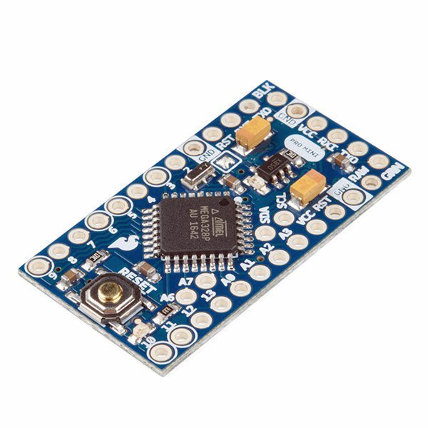
SparkFun SparkFun Arduino Pro Mini 328 (5 V, 16 MHz)
The Arduino Pro Mini is a microcontroller board based on the ATmega328P. It has 14 digital input/output pins (of which 6 can be used as PWM outputs), 6 analog inputs, an on-board resonator, a reset button, and holes for mounting pin headers. A six pin header can be connected to an FTDI cable or SparkFun breakout board to provide USB power and communication to the board. The Arduino Pro Mini is intended for semi-permanent installation in objects or exhibitions. The board comes without pre-mounted headers, allowing the use of various types of connectors or direct soldering of wires. The pin layout is compatible with the Arduino Mini. The Arduino Pro Mini was designed and is manufactured by SparkFun Electronics. Specifications Microcontroller ATmega328P Board Power Supply 5-12 V Circuit Operating Voltage 5 V Digital I/O Pins 14 PWM Pins 6 UART 1 SPI 1 I²C 1 Analog Input Pins 6 External Interrupts 2 DC Current per I/O Pin 40 mA Flash Memory 32 KB of which 2 KB used by bootloader SRAM 2 KB EEPROM 1 KB Clock Speed 16 MHz Dimensions 18 x 33.3 mm (0.7 x 1.3") Downloads Eagle files Schematics
€ 14,95€ 7,95Best Price
-

FNIRSI FNIRSI HT-P1B Pro Mini Hot Plate (150 W)
The FNIRSI HT-P1B Pro is a compact mini hot plate designed for PCB soldering, desoldering, and SMD rework. With up to 150 W of heating power, precise PID temperature control, and an adjustable temperature range of 100°C to 350°C, it delivers fast and stable heating for electronics projects. The 50 x 50 mm heating surface is ideal for small PCBs and electronic components. Two operating modes – constant temperature heating and simulated reflow soldering – provide flexibility for different applications. A 1.44-inch color display, three temperature presets, and built-in safety features ensure convenient operation. With DC and USB-C PD 3.1 support, a compact design, and an included 100 W USB-C charger, the HT-P1B Pro is a practical tool for makers, electronics enthusiasts, and repair professionals. Features Up to 150 W Heating Power: Fast heating with adjustable power settings from 30 W to 150 W. Precise PID Temperature Control: Adjustable range from 100°C to 350°C with ±3°C temperature stability. Dual Operating Modes: Constant temperature heating and simulated reflow soldering. 50 × 50 mm Heating Surface: Ideal for small PCBs, SMD soldering, and component rework. Flexible Power Input: DC 12-28 V (up to 150 W) and USB-C PD 3.1 (up to 140 W). Three Temperature Presets: Quick access to frequently used temperature settings. 1.44-inch Color Display: Shows temperature, voltage, power, heating time, and operating status. Built-in Safety Features: Over-temperature, low-voltage, prolonged-heating, and tilt protection. Specifications Power Input DC 12-28 V / USB-C PD Power Range 30-150 W Standby Power 1.6 W Temperature Range 100-350°C (212-662°F) Temperature Stability ±3°C Heating Area 50 x 50 mm Display 1.44" Color Screen Tilt Detection 20°-50° Protocol PD 3.1 Dimensions 68.8 x 81.8 x 44.5 mm Weight 157 g Included 1x FNIRSI HT-P1B Preheating Station 1x FNIRSI 100 W PD GaN Charger (EU) 1x FNIRSI 100 W USB-C Fast-charging Cable 1x Heat-Resistant Silicone Cover 1x Storage Case 1x Manual Downloads Manual
€ 99,95€ 84,95Best Price
-
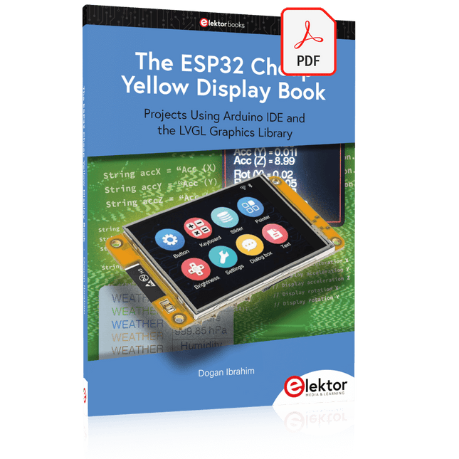
Elektor Digital The ESP32 Cheap Yellow Display Book (PDF)
Projects Using Arduino IDE and the LVGL Graphics Library The ESP32 is probably one of the most popular microcontrollers used by many people, including students, hobbyists, and professional engineers. Its low cost, coupled with rich features makes it a popular device to use in many projects. Recently, a board called the ESP32 Cheap Yellow Display (CYD for short) is available from its manufacturers. The board includes a standard ESP32 microcontroller together with a 320x240 pixel TFT display. Additionally, the board provides several connectors for interfaces such as GPIO, serial port (TX/RX), power and Ground. The inclusion of a TFT display is a real advantage as it enables users to design complex graphics-based projects without resorting to an external LCD or graphics displays. The book describes the basic hardware of the ESP32 CYD board and provides details of its on-board connectors. Many basic, simple, and intermediate-level projects are given in the book based on the ESP32 CYD, using the highly popular Arduino IDE 2.0 integrated development environment. The use of both the basic graphics functions and the use of the popular LVGL graphics library are discussed in the book and projects are given that use both types of approaches. All the projects given in the book have been tested and are working. The block diagram, circuit diagram, and the complete program listings and program descriptions of all the projects are given with explanations. Readers can use the LVGL graphics library to design highly popular eye-catching full-color graphics projects using widgets such as buttons, labels, calendars, keypads, keyboards, message boxes, spinboxes, sliders, charts, tables, menus, bars, switches, drop-down lists, animations, and many more widgets.
€ 29,95
Members: € 26,96
-

Elektor Bundles 555 Timer Projects (Bundle)
This bundle is all about designing projects based on the 555 timer IC. The book features over 45 fully tested and documented projects. Together with the kit, which contains more than 130 through-hole components, you can build all the projects described on a breadboard. The setup also makes it easy to modify and experiment with the projects. Over 45 Builds for the Legendary 555 Chip (and the 556, 558) Some of the projects in the book are: Alternately Flashing Two LEDs Changing LED Flashing Rate Touch Sensor On/Off Switch Switch On/Off Delay Light-Dependent Sound Dark/Light Switch Tone Burst Generator Long Duration Timer Chasing LEDs LED Roulette Game Traffic Lights Continuity Tester Electronic Lock Switch Contact Debouncing Toy Electronic Organ Multiple Sensor Alarm System Metronome Voltage Multipliers Electronic Dice 7-Segment Display Counter Motor Control 7-Segment Display Dice Electronic Siren Various Other Projects Kit Contents Resistors 1x 15 kΩ 1x 68 kΩ 2x 47 kΩ 1x 82 kΩ 2x 820 Ω 1x 8.2 kΩ 3x 10 kΩ 1x 1.8 kΩ 1x 6.8 kΩ 14x 2.2 kΩ 10x 680 Ω 1x 27 kΩ 1x 5.6 kΩ 1x 560 kΩ 1x 4.7 kΩ 1x 3.3 kΩ 3x 33 kΩ 1x 36 kΩ 2x 100 kΩ 5x 1 kΩ 1x 3.9 kΩ 2x 56 kΩ 2x 12 kΩ 1x 10 kΩ potentiometer 1x 1 MΩ potentiometer 2x 50 kΩ potentiometer 3x 20 kΩ potentiometer 1x 10 kΩ potentiometer 1x 10 kΩ potentiometer 1x 50 kΩ potentiometer 1x 100 kΩ potentiometer 1x 50 kΩ potentiometer Capacitors 1x 0.33 μF 1x 1 μF 1x 10 nF 1x 22 nF 1x 47 nF 1x 100 nF 1x 10 μF electrolytic 1x 33 μF electrolytic 2x 100 μF electrolytic LEDs 10x 5 mm red LED 10x 3 mm red LED 3x 3 mm yellow LED 3x 3 mm green LED 1x Common-cathode 7-segment LED Semiconductors 3x 555 timer 1x CD4017 counter 1x CD4026 counter 1x CD4011 NAND gate 4x 1N4148 diode 1x IRFZ46N MOSFET 1x Thermistor 1x Light dependent resistor (LDR) Miscellaneous 1x Passive buzzer 1x Active buzzer 1x SG90 servo 1x 8 Ω mini loudspeaker 1x 9 V DC brushed motor 1x 5 V relay 1x 9 V battery clip 7x Pushbutton switches 1x Breadboard 1x Breadboard jumper wires
€ 69,95€ 54,95Best Price
-
Miniware Miniware MDP-P906 Digital Power Supply (300 W)
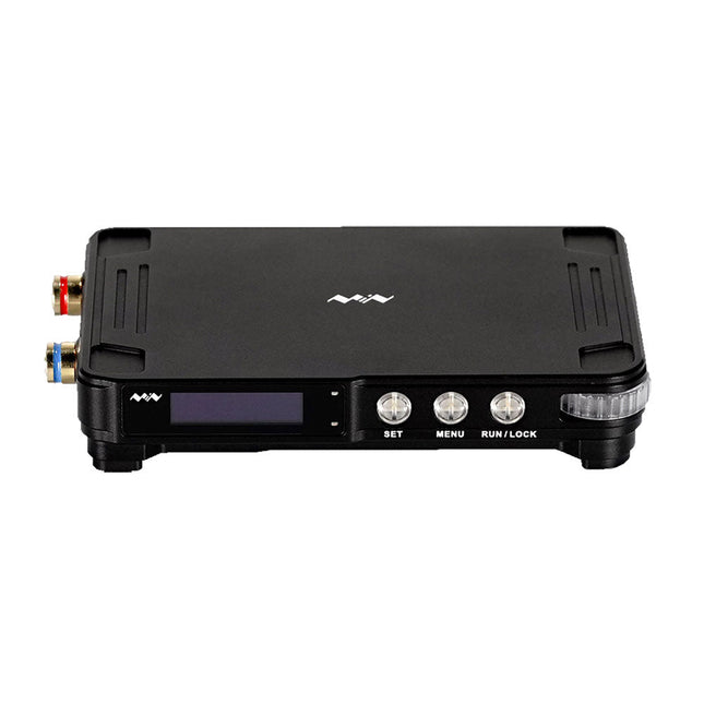
MDP-P906 has a built-in cooling fan, and maximum output power of up to 300 W, which meets a wider range of testing needs and application scenarios. Through 2.4 GHz wireless communication, it can be connected to MDP-M01 Smart Digital Monitor module to realize the free combination of multiple channels of 300 W per channel. MDP-P906 has the index, stability and reliability comparable to a professional power supply. It can output pure current, and provide powerful functions such as programmable output, timing output, timing control, automatic compensation, boost mode, etc., making itself a real cost-effective, smart and customized programmable linear DC power supply. MDP-P906 adopts a precision CNC machined aluminum alloy shell, with fine workmanship, novel, mini and beautiful appearance, it completely subverts the rigid image of traditional desktop power supply. With stackable modular design and wireless communication function, MDP-P906 can work independently or paired, both on the workbench, and be carried out for on-site maintenance. MDP-P906 is a perfect solution for electronic engineer, especially field application engineers to meet different needs of power sources. Built-in silent cooling fan, instant cooling, ensure a stable and efficient output! Smart linear compensation, constant voltage & constant current Positive & negative output, series boost, parallel current sharing Applications Universal tests and teaching experiments in R&D laboratory Maintenance of digital products Property verification and fault diagnosis of devices and circuits Emergency power supply for model airplanes and vehicles Power supply testing of RF and microwave circuits or modules Quality control and quality inspection Supply purified power for high-accuracy digital-analog hybrid circuits and Hi-Fi audio devices Specifications Input DC 4.2-30 V/14 A (Max)QC 3.0/PD2.0, 20 V/5 A (Max) Output 0-30 V/0-10 A, 300 W (Max) Conversion efficiency 95% Output resolution 10 mV/2 mA, up to 1 mV/1 mA via Display Control module Output accuracy 0.03%+5 mV0.05%+2 mV Adjustment rate Load adjustment rate <±0.01%Power adjustment rate <±0.01% Ripple and noise <250 uVrms, 3 mVpp; 2 mArms Transient response <4 uS Safety protections Input over-voltage, under-voltage, reverse connection protection, output over-current, back-flow protection and over-temperature protection Others Automatically shut-down and enter micro-power modeSupport USB firmware upgrade Dimensions 112 x 66 x 20 mm Weight 181 g Included 1x MDP-P906 Digital Power Supply 2x Output Cable 1x User Manual Downloads User Manual v1.1 Firmware v1.32
€ 171,95


