Le téléchargement intégral de ce numéro est disponible pour nos membres GOLD et GREEN sur le site Elektor Magazine !
Pas encore membre ? Cliquez ici.
le téléphone à cadran rotatif comme télécommandepour allumer la lumière, composez le 1 ; pour la cafetière, composez le 2
contrôleur de vitesse par GPSplus de contraventions pour excès de vitesse
stroboscope RVB avec Arduinoun instrument utile, instructif et distrayant
bouton poussoir d'urgence sans filsécurité renforcée avec LoRa
démarrer en électronique...l'émetteur-suiveur
comparateur à hysteresis à niveaux indépendantssimulations, feuilles de calcul et algèbre
analyseur d?impédance basé sur un ESP32simple, comportant peu de composants et de faible coût?!
visite à domicileencourageons les réalisations personnelles
La carte d'apprentissage MCCAB pour Arduino Nanoplateforme pour le cours ?Microcontrollers Hands-On Course?
sur le vifLuddisme moderne
B.a.ba?capteur : le capteur de température DS18B20connexion au bus 1-Wire
quels standards pour unifier la domotique??Matter et Thread se distinguent
Matter, ou la concorde des objetsTestez Matter avec la carte Thing Plus Matter et Simplicity Studio
Infographie : IdO et capteurs
Matter, ExpressLink, Rainmaker ? de quoi s'agit-il ?questions et réponses avec Amey Inamdar, directeur du marketing technique chez Espressif
guide d?introduction à la sélection de kits de développement de microcontrôleurs pour applications IoT et IIoT
un condensateur n?est pas toujours capacitif?!
horloge NTP en CircuitPythonpourquoi utiliser ce langage de programmation ?
construisez un écran IdO sympaavec le Phambili Newt
détecteur de mouvement Doppler HB100Théorie et pratique
Guide de programmation bare-metalpour STM32 et autres microcontrôleurs
revue multimètre Siglent SDM3045X
microprocesseurs pour systèmes embarquésdrôle de composants, la série
la documentation des microcontrôleurs sans peine (3)schémas de principe, et autres documents
station météo LoRa à faible puissanceréalisez vous-même une station météo à longue portée
Transverter pour la bande 70 cm
Climate Calling EngineersMove Fast and Fix Things
Hexadoku
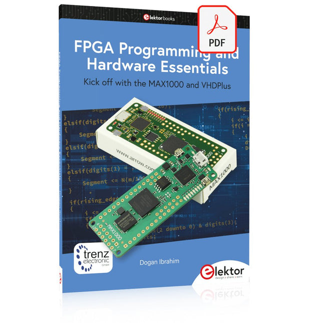
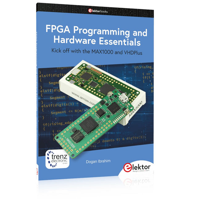
Kick off with the MAX1000 and VHDPlus
Ready to Master FPGA Programming? In this guide, we’re diving into the world of Field Programmable Gate Arrays (FPGAs) – a configurable integrated circuit that can be programmed after manufacturing. Imagine bringing your ideas to life, from simple projects to complete microcontroller systems!
Meet the MAX1000: a compact and budget-friendly FPGA development board packed with features like memory, user LEDs, push-buttons, and flexible I/O ports. It’s the ideal starting point for anyone wanting to learn about FPGAs and Hardware Description Languages (HDLs).
In this book, you’ll get hands-on with the VHDPlus programming language – a simpler version of VHDL. We’ll work on practical projects using the MAX1000, helping you gain the skills and confidence to unleash your creativity.
Get ready for an exciting journey! You’ll explore a variety of projects that highlight the true power of FPGAs. Let’s turn your ideas into reality and embark on your FPGA adventure – your journey starts now!
Exciting Projects You’ll Find in This Book
Arduino-Driven BCD to 7-Segment Display Decoder
Use an Arduino Uno R4 to supply BCD data to the decoder, counting from 0 to 9 with a one-second delay
Multiplexed 4-Digit Event Counter
Create an event counter that displays the total count on a 4-digit display, incrementing with each button press
PWM Waveform with Fixed Duty Cycle
Generate a PWM waveform at 1 kHz with a fixed duty cycle of 50%
Ultrasonic Distance Measurement
Measure distances using an ultrasonic sensor, displaying the results on a 4-digit 7-segment LED
Electronic Lock
Build a simple electronic lock using combinational logic gates with push buttons and an LED output
Temperature Sensor
Monitor ambient temperature with a TMP36 sensor and display the readings on a 7-segment LED
Downloads
Software
PIC und AVR verstehen
In diesem Buch werden wir uns ausschließlich mit 8-Bit-Mikrocontrollern beschäftigen, und zwar mit Mikrocontrollern der 8-Bit-PIC- und der 8-Bit-AVR-Mikrocontroller-Linien. Bei der PIC-Familie handelt es sich dabei um PIC10, PIC12, PIC16 und PIC18; bei der AVR-Familie um ATtiny, ATmega und ATxmega. Die vorgestellten 8-Bit-Chips sind für sehr viele Anwendungen vollkommen ausreichend und preislich auch attraktiv.
Durch die Lektüre des Buches erhalten Sie ein fundiertes Wissen über die genannten 8-Bit-Mikrocontroller, über ihre Architektur, ihre Pinbelegungen und über ihre Programmierung.
Weil wir uns in diesem Buch mit den Grundlagen der Architektur der PICs und AVRs vertraut machen möchten, werden wir auch für alle PIC- und AVR-Anwendungen Assembler einsetzen, denn die Assembler-Sprache erlaubt es, die Technik im Detail kennenzulernen. Wenn man wirklich wissen möchte, was sich im Mikrocontroller abspielt, greift man zu Assembler. Damit hat man die beste Gelegenheit, sehr nah an den Kern zu kommen. Und wenn man schon einen Mikrocontroller-Typ kennengelernt und verstanden hat, ist es bei dem nächsten deutlich einfacher, auch wenn er von einem anderen Hersteller kommt. Bei anderen Programmiersprachen bleibt die Technik immer ziemlich tief versteckt.
Die Assembler-Beispiele sind so einfach gestaltet, dass sie jeder mit den im Buch aufgezeigten Programmiertechniken erstellen kann. Weil es sich um einfache Beispiele handelt, werden wir sie alle auf einer universellen Lochrasterplatine realisieren. Manche sind auch auf einem Experimentier-Breadboard umsetzbar.
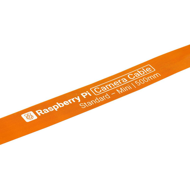
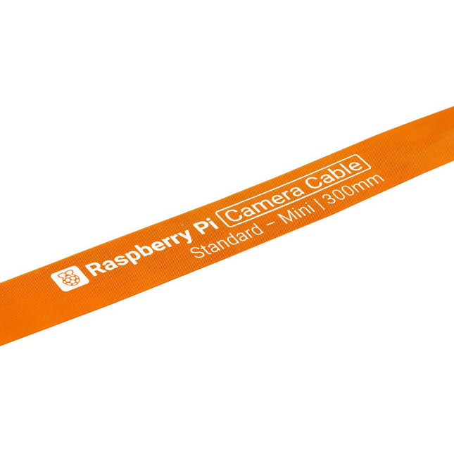
Raspberry Pi 5 provides two four-lane MIPI connectors, each of which can support either a camera or a display. These connectors use the same 22-way, 0.5 mm-pitch “mini” FPC format as the Compute Module Development Kit, and require adapter cables to connect to the 15-way, 1 mm-pitch “standard” format connectors on current Raspbery Pi camera and display products.These mini-to-standard adapter cables for cameras and displays (note that a camera cable should not be used with a display, and vice versa) are available in 200 mm, 300 mm and 500 mm lengths.
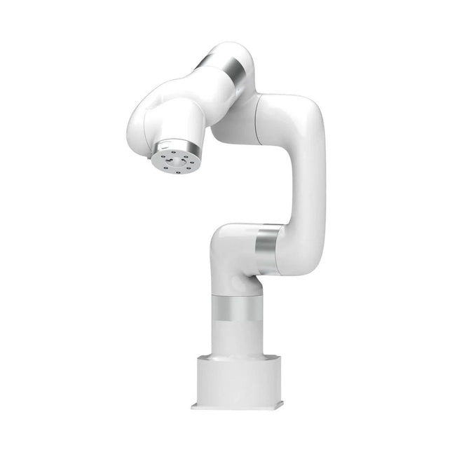
This multi-axis robot perfectly balances power and size.
Features
6 Axis
Payload: 3.5 kg
Reach: 700 mm
Repeatability: 0.1 mm
Max Speed 1000 mm/s
Applications
Machine Tending
Bin Picking
Mobile platform
Lab Automation
Robotic Research
Durable Collaborative robots for your automation
Industrial-grade harmonic drive and servomotors guarantee 24/7 working without stop.
Crafted from Carbon fiber, 15 kg weight makes it possible for easier deployment.
Flexible deployment with safe feature
Hand teaching, lightweight, space-saving and easy to re-deploy to multiple applications without changing your production layout. Perfectly for recurrent tasks.
Collision detection is available for all of our cobots. Your safety is always the top priority.
Graphical interface for beginner-friendly programming
Compatible with various of operation systems, including macOS and Windows.
Web-based technology compatible with all major browsers.
Drag and drop to create your code in minutes.
Powerful and open source SDK at your fingertips
Fully functional open-source Python/C++ SDK provides more flexible programming.
ROS/ROS2 packages are ready-to-go.
Example codes help you to deploy the robotic arm smoothly.
Specifications
UFactory 850
xArm 5
xArm 6
xArm 7
Payload
5 kg
3 kg
5 kg
3.5 kg
Reach
850 mm
700 mm
700 mm
700 mm
Degrees of freedom
6
5
6
7
Repeatability
±0.02 mm
±0.1 mm
±0.1 mm
±0.1 mm
Maximum Speed
1 m/s
1 m/s
1 m/s
1 m/s
Weight (robot arm only)
20 kg
11.2 kg
12.2 kg
13.7 kg
Maximum Speed
180°/s
180°/s
180°/s
180°/s
Joint 1
±360°
±360°
±360°
±360°
Joint 2
-132°~132°
-118°~120°
-118°~120°
-118°~120°
Joint 3
-242°~3.5°
-225°~11°
-225°~11°
±360°
Joint 4
±360°
-97°~180°
±360°
-11°~225°
Joint 5
-124°~124°
±360°
-97°~180°
±360°
Joint 6
±360°
±360°
-97°~180°
Joint 7
±360°
Hardware
Ambient Temperature Range
0-50°C
Power Consumption
Min 8.4 W, Typical 200 W, max 400 W
Input Power Supply
24 V DC, 16.5 A
Footprint
Ø 126 mm
Materials
Aluminum, Carbon Fiber
Base Connector Type
M5x5
ISO Class Cleanroom
5
Robot Mounting
Any
End Effector Communication Protocol
Modbus RTU(rs485)
End Effector I/O
2x DI/2x DO/2x AI/1x RS485
Communication Mode
Ethernet
Included
1x xArm 7 robotic arm
1x AC control box
1x Robotic arm power cable
1x Robotic arm end effector adapter cable
1x Robotic arm signal cable
1x Control box power cable
1x Network cable
1x Mounting tool
1x Quick start guide
PIC und AVR verstehen
In diesem Buch werden wir uns ausschließlich mit 8-Bit-Mikrocontrollern beschäftigen, und zwar mit Mikrocontrollern der 8-Bit-PIC- und der 8-Bit-AVR-Mikrocontroller-Linien. Bei der PIC-Familie handelt es sich dabei um PIC10, PIC12, PIC16 und PIC18; bei der AVR-Familie um ATtiny, ATmega und ATxmega. Die vorgestellten 8-Bit-Chips sind für sehr viele Anwendungen vollkommen ausreichend und preislich auch attraktiv.
Durch die Lektüre des Buches erhalten Sie ein fundiertes Wissen über die genannten 8-Bit-Mikrocontroller, über ihre Architektur, ihre Pinbelegungen und über ihre Programmierung.
Weil wir uns in diesem Buch mit den Grundlagen der Architektur der PICs und AVRs vertraut machen möchten, werden wir auch für alle PIC- und AVR-Anwendungen Assembler einsetzen, denn die Assembler-Sprache erlaubt es, die Technik im Detail kennenzulernen. Wenn man wirklich wissen möchte, was sich im Mikrocontroller abspielt, greift man zu Assembler. Damit hat man die beste Gelegenheit, sehr nah an den Kern zu kommen. Und wenn man schon einen Mikrocontroller-Typ kennengelernt und verstanden hat, ist es bei dem nächsten deutlich einfacher, auch wenn er von einem anderen Hersteller kommt. Bei anderen Programmiersprachen bleibt die Technik immer ziemlich tief versteckt.
Die Assembler-Beispiele sind so einfach gestaltet, dass sie jeder mit den im Buch aufgezeigten Programmiertechniken erstellen kann. Weil es sich um einfache Beispiele handelt, werden wir sie alle auf einer universellen Lochrasterplatine realisieren. Manche sind auch auf einem Experimentier-Breadboard umsetzbar.
Le téléchargement intégral de ce numéro est disponible pour nos membres GOLD et GREEN sur le site Elektor Magazine !
Pas encore membre ? Cliquez ici.
Raspberry Pi Pico comme analyseur de spectredes FFT avec du matériel bon marché
régulateur de tension linéaire ±40 Vune alimentation de qualité pour l'amplificateur de puissance Fortissimo-100... et d'autres !
la communication sans fil des microcontrôleurs devient flexiblel'EEPROM ouvre des perspectives de mise en réseau pour les microcontrôleurs sans fil
5000 ? à gagner !participez au concours STM32 Wireless Innovation Design Contest
2023 : l'odyssée de l'IAdémarrer avec l'interpréteur de code de ChatGPT
LoRa, un couteau suisse (1)le protocole LoRa et ses avantages
puit de courant réglable avec générateur d'horloge intégrétestez vos alimentations, convertisseurs de tension et batteries
les nouvelles cartes Arduino UNO R4 Minima et WiFi
des potentiomètres logarithmiquesqui sont exponentiels !
Carte d'interface pour pilote de moteurUn BoB pour un pilote de moteur à courant continu de 5 A avec une taille de 3×3 mm
sur le vifdanger de l'électronique
une architecture cellulaire offre-t-elle la plus basse consommation pour l'Internet des objets (IdO) ?caractéristiques énergétiques des technologies LTE-M et NB-IoT pour le déploiement de réseaux étendus à basse consommation (LPWAN)
communication sans fil dans les systèmes IoT à l'aide de modules Arduino MKRnormes de communication des modules Arduino pour l'IoT
pertes en courant alternatif dans les composants magnétiquesévitez la surchauffe des inductances !
optimiser son déploiement cloud grâce aux appareils de mesure
implémentation de Matter : que faut-il pour déployer les appareils Matter ?
le YARD Stick Oneun outil de test sans fil pour les fréquences jusqu?à 1 GHz
relais à verrouillagedrôle de composant, la série
PIC O?Clock ? prendre le pouls du tempsconception d'un récepteur de signaux horaires SDR
Due Diligence DirectiveBusiness as Usual Will Not Do
démarrer en électronique?amplificateur de tension
enregistreur d'infrasons avec l'Arduino Pro Miniun projet extrait du livre 'Arduino & Co.' d'Elektor
compteur d'énergie basé sur le cloudavec un module ESP32 et un capteur de tension/courant PZEM-004T
guide de programmation Bare-Metal (2)timer précis, UART et débogage
Hexadoku
The OWON SDS1102 is an affordable benchtop digital oscilloscope that combines solid performance with essential measurement features. This 2-channel oscilloscope offers a 100 MHz bandwidth, a 1 GS/s sampling rate, a 7-inch LCD display, and a 10 kpts memory depth, making it a practical choice for everyday electronics testing, troubleshooting, and education.
The SDS1102 features a simplified trigger system with level and edge triggering, making it easy to capture and analyze common signals. It is designed for applications that do not require deep memory or advanced trigger functions, offering a straightforward and cost-effective solution for basic signal analysis.
Features
Bandwidth: 100 MHz
2 channels
Sample rate: 1 GS/s
Ultra-thin body
7-inch high-res LCD
SCPI and LabVIEW supported
Specifications
Bandwidth
100 MHz
Horizontal Scale (s/div)
5 ns/div – 1000 s/div
Channel
2
Vertical Sensitivity
5 mV/div – 5 V/div (at input)
DC Gain Accuracy
3%
Vertical Resolution (A/D)
8 bits (2 channels simultaneously)
Input
Input Impedance
1 MΩ, 10 pF
Input Coupling
AC, DC, GND
Max Input Voltage
±400 V, CATI, CATII
Passive probes
х1; х10
Probe Attenuation Factor
х1; х10; х100; х1000
Trigger System
Trigger Mode
Auto, Normal, Single
Trigger Type
Edge, Video
Edge Trigger Source
CH1, CH2
Video Trigger
Sampling Type
Real-time
Sample Rate
1 GS/s
Equivalent Sample Rate
No
Wavelength
10K pts
Interpolation
sin(x)/x
Measurement and Mathematical Treatment System
Automatic Measurement
Vpp, Vavg, RMS, Frequency, Period, Vmax, Vmin, Vtop, Vbase, Width, Overshoot, Pre-shootRise time, Fall time, +Width, -Width, +Duty, -Duty, Delay A→B, Delay A→B, area, cycle area
Math Functions
Addition, Subtraction, Multiplication, Division, FFT
General Characteristics
Display type
7" color LCD
Display Resolution
800 x 480
Power
100-240 V, 45-440 Hz, <15 W
Dimensions
301 x 70 x 152 mm
Weight
1.1 kg
Included
1x OWON SDS1102 Oscilloscope
2x Oscilloscope probes
1x Probe adjust
1x Mains power cord
1x USB cable
1x CD-Rom
1x Quick guide
Downloads
Quick Guide
Manual
PC Software
SCPI Commands
Programming and Projects for the Minima and WiFi
Based on the low-cost 8-bit ATmega328P processor, the Arduino Uno R3 board is likely to score as the most popular Arduino family member, and this workhorse has been with us for many years. Eleven years later, the long-overdue successor, the Arduino Uno R4, was released. It is built around a 48 MHz, 32-bit Arm Cortex-M4 microcontroller and provides significantly expanded SRAM and Flash memory. Additionally, a higher-precision ADC and a new DAC are added to the design. The Uno R4 board also supports the CAN Bus with an interface.
Two versions of the board are available: Uno R4 Minima, and Uno R4 WiFi. This book is about using these new boards to develop many different and interesting projects with just a handful of parts and external modules. All projects described in the book have been fully tested on the Uno R4 Minima or the Uno R4 WiFi board, as appropriate.
The project topics include the reading, control, and driving of many components and modules in the kit as well as on the relevant Uno R4 board, including
LEDs
7-segment displays (using timer interrupts)
LCDs
Sensors
RFID Reader
4x4 Keypad
Real-time clock (RTC)
Joystick
8×8 LED matrix
Motors
DAC (Digital-to-analog converter)
LED matrix
WiFi connectivity
Serial UART
CAN bus
Infrared controller and receiver
Simulators
… all in creative and educational ways with the project operation and associated software explained in great detail.
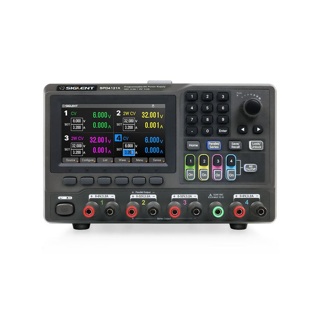
The Siglent SPD4121X is a 4-channel DC Linear Programmable Power Supply equipped with a 4.3-inch TFT-LCD display, friendly human-machine interface, and excellent performance indicators. Real-time waveform display provides engineers with an informative user interface.
SPD4121X offers a total output power of 285 W with a resolution of 1 mV/1 mA. The maximum voltage and current for each channel are as follows:
CH1: 15 V/1.5 A
CH2: 12 V/10 A
CH3: 12 V/10 A
CH4: 15 V/1.5 A
Features
Rated output power: 285 W
Rated voltage: 32 V, 12 V, 30 V
Up to four high-precision power supplies with independent controllable outputs, supporting CH2 and CH3 series and parallel connections
Clear graphical interface with waveform and timer display modes
5-digit voltage and current display with minimum resolution of 1 mV, 1 mA
Fast output response time: <50us
The high current channel support remote voltage compensation sense function. The maximum compensation voltage is 0.6 V
Overvoltage protection and overcurrent protection or safe and accurate operation
Equipped with a 4.3-inch TFT-LCD display (480 x 272 resolution)
USB and LAN standard communication
USB-GPIB module is optional
Excellent channel density with up to 4 channels in a 3U half rack package
Internal data storage for setups and parameters
Embedded Web Server with instrument communication that doesn’t require software installation
Fully SCPI programming command set support as well as a LabView driver for remote control and system automation
Specifications
SPD4323X
SPD4121X
SPD4306X
Channel Output
CH1: Voltage 0 to 6 V Current 0 to 3.2 ACH2: Voltage 0 to 32 V Current 0 to 3.2 ACH3: Voltage 0 to 32 V Current 0 to 3.2 ACH4: Voltage 0 to 6 V Current 0 to 3.2 A
CH1: Voltage 0 to 15 V Current 0 to 1.5 ACH2: Voltage 0 to 12 V Current 0 to 10 ACH3: Voltage 0 to 12 V Current 0 to 10 ACH4: Voltage 0 to 15 V Current 0 to 1.5 A
CH1: Voltage 0 to 15 V Current 0 to 1.5 ACH2: Voltage 0 to 30 V Current 0 to 6 ACH3: Voltage 0 to 30 V Current 0 to 6 ACH4: Voltage 0 to 15 V Current 0 to 1 A
Resolution
1 mV, 1 mA
1 mV, 1 mA
1 mV, 1 mA
Setting Accuracy
Voltage: ±(0.03% of reading+10) mV, Current: ±(0.3% of reading+10) mA
Voltage: ±(0.03% of reading+10) mV, Current: ±(0.3% of reading+10) mA
Voltage: ±(0.03% of reading+10) mV, Current: ±(0.3% of reading+10) mA
Readback Accuracy
Voltage: ±(0.03% of reading+10) mV, Current: ±(0.3% of reading+10) mA
Voltage: ±(0.03% of reading+10) mV, Current: ±(0.3% of reading+10) mA
Voltage: ±(0.03% of reading+10) mV, Current: ±(0.3% of reading+10) mA
Display
4.3" TFT-LCD 5-digit voltage and current display
4.3" TFT-LCD 5-digit voltage and current display
4.3" TFT-LCD 5-digit voltage and current display
Output power
240 W
285 W
400 W
Included
1x Siglent SPD4121X Power Supply
1x Power cord (EU)
1x Output test cord (3 A)
1x USB cable
1x Quick start guide
Downloads
Datasheet
Manual
Quick start
Kick off with the MAX1000 and VHDPlus
Ready to Master FPGA Programming? In this guide, we’re diving into the world of Field Programmable Gate Arrays (FPGAs) – a configurable integrated circuit that can be programmed after manufacturing. Imagine bringing your ideas to life, from simple projects to complete microcontroller systems!
Meet the MAX1000: a compact and budget-friendly FPGA development board packed with features like memory, user LEDs, push-buttons, and flexible I/O ports. It’s the ideal starting point for anyone wanting to learn about FPGAs and Hardware Description Languages (HDLs).
In this book, you’ll get hands-on with the VHDPlus programming language – a simpler version of VHDL. We’ll work on practical projects using the MAX1000, helping you gain the skills and confidence to unleash your creativity.
Get ready for an exciting journey! You’ll explore a variety of projects that highlight the true power of FPGAs. Let’s turn your ideas into reality and embark on your FPGA adventure – your journey starts now!
Exciting Projects You’ll Find in This Book
Arduino-Driven BCD to 7-Segment Display Decoder
Use an Arduino Uno R4 to supply BCD data to the decoder, counting from 0 to 9 with a one-second delay
Multiplexed 4-Digit Event Counter
Create an event counter that displays the total count on a 4-digit display, incrementing with each button press
PWM Waveform with Fixed Duty Cycle
Generate a PWM waveform at 1 kHz with a fixed duty cycle of 50%
Ultrasonic Distance Measurement
Measure distances using an ultrasonic sensor, displaying the results on a 4-digit 7-segment LED
Electronic Lock
Build a simple electronic lock using combinational logic gates with push buttons and an LED output
Temperature Sensor
Monitor ambient temperature with a TMP36 sensor and display the readings on a 7-segment LED
Downloads
Software
Raspberry Pi 5 provides two four-lane MIPI connectors, each of which can support either a camera or a display. These connectors use the same 22-way, 0.5 mm-pitch “mini” FPC format as the Compute Module Development Kit, and require adapter cables to connect to the 15-way, 1 mm-pitch “standard” format connectors on current Raspbery Pi camera and display products.These mini-to-standard adapter cables for cameras and displays (note that a camera cable should not be used with a display, and vice versa) are available in 200 mm, 300 mm and 500 mm lengths.