Over 40 Fully Tested ESP32 Projects Using Arduino IDE and the LVGL Graphics Library
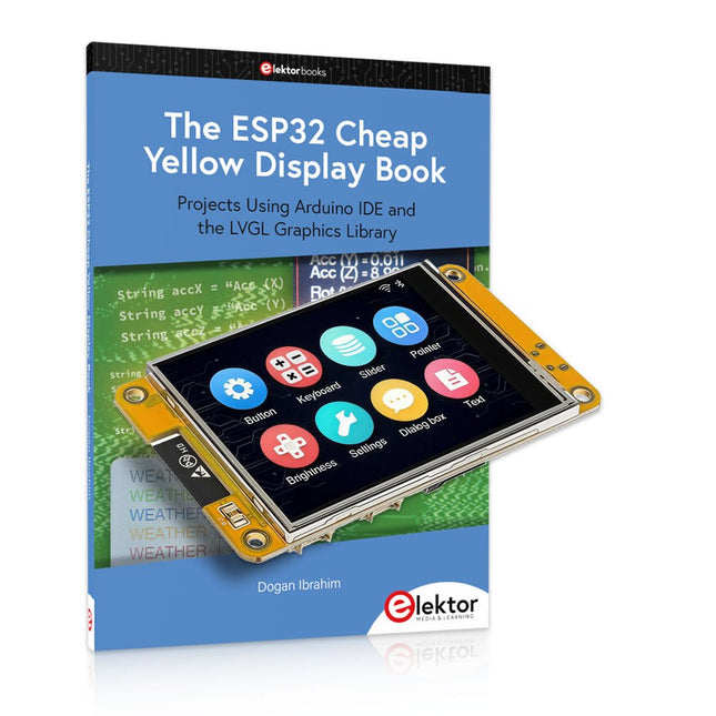
This bundle includes the ESP32 Cheap Yellow Display (CYD) – a compact development board combining a standard ESP32 microcontroller with a 320x240 pixel TFT color display. The board also features multiple connectors for GPIO, serial communication (TX/RX), power, and ground. The built-in display is a major advantage, allowing users to create complex, graphics-based projects without the need for external LCDs or displays.
The accompanying book introduces the CYD board's hardware and on-board connectors in detail. It provides a range of beginner to intermediate-level projects developed using the popular Arduino IDE 2.0. Both basic graphics functions and the powerful LVGL graphics library are covered, with practical projects illustrating each approach.
All included projects have been fully tested and are ready to use. The book provides block diagrams, circuit schematics, complete code listings, and step-by-step explanations. With the LVGL library, readers can create modern, full-color graphical interfaces using widgets such as buttons, labels, sliders, calendars, keyboards, charts, tables, menus, animations, and more.
ESP32 Cheap Yellow Display Board
This development board (also known as "Cheap Yellow Display") is powered by the ESP-WROOM-32, a dual-core MCU with integrated Wi-Fi and Bluetooth capabilities. It operates at a main frequency of up to 240 MHz, with 520 KB SRAM, 448 KBROM, and a 4 MB Flash memory. The board features a 2.8-inch display with a resolution of 240x320 and resistive touch.
Furthermore, the board includes a backlight control circuit, touch control circuit, speaker drive circuit, photosensitive circuit, and RGB-LED control circuit. It also provides a TF card slot, serial interface, DHT11 temperature and humidity sensor interface, and additional IO ports.
The module supports development in Arduino IDE, ESP-IDE, MicroPython, and Mixly.
Applications
Image transmission for Smart Home device
Wireless monitoring
Smart agriculture
QR wireless recognition
Wireless positioning system signal
And other IoT applications
Specifications
Microcontroller
ESP-WROOM-32 (Dual-core MCU with integrated Wi-Fi and Bluetooth)
Frequency
Up to 240 MHz (computing power is up to 600 DMIPS)
SRAM
520 KB
ROM
448 KB
Flash
4 MB
Operating voltage
5 V
Power consumption
approx. 115 mA
Display
2.8-inch color TFT screen (240 x 320)
Touch
Resistive Touch
Driver chip
ILI9341
Dimensions
50 x 86 mm
Weight
50 g
Downloads
GitHub
This bundle contains:
The ESP32 Cheap Yellow Display Book (normal price: €35)
ESP32 Cheap Yellow Display Board (normal price: €25)
1x ESP32 Dev Board with 2.8" Display and acrylic Shell
1x Touch pen
1x Connector cable
1x USB cable
Touch-GUI voor ESP32 en Raspberry & cografische gebruikersinterface met de LittlevGL-bibliotheek
“Niet zomaar een project”vraaggesprek met Gábor Kiss-Vámosi, ontwikkelaar van LittlevGL
Capaci-metermet tweecijferig LED-display in dekatron-stijl
Hoe... een mechanisch contact of schakelaar ontdendereneen schakelaar is open of gesloten – toch?
Developer's Zonetips & trucs, vakkunstigheden en andere nuttige informatie
Uitbreidbaar milieumonitorsysteempubliceert gegevens op IoT-platforms
Multitasking met de ESP32Multitasking met de ESP32 taakgeoriënteerd programmeren met FreeRTOS en de Arduino IDE
Interactiefcorrecties & updates || vragen & antwoorden
Autoverlichting tunenlegaal, illegaal – maakt wél uit!
Review Toolcraft digitaal soldeerstation
Arduino Pro IDEeen eerste indruk
Twee warmtebeeldcamera’s vergeleken
Uit het leven gegrepende inrichting van een lab en werkplaats
Monsanto MAN1 LED-displayvreemde onderdelen
Theetimereen experiment met energy harvesting
Eenfase 1 kW AC-motorsturingdrie bedrijfsmodi: perioderegeling, fase-afsnijding en fase-aansnijding
Snel 3,5'-touchscreen voor de Raspberry Pipresteert beter voor hetzelfde geld
Oost West Lab Besteen blik in het allerheiligste, waar onbevoegden geen toegang hebben...
Eerste stappen met RISC-Vhet LoFive-board onder de loep
LoRa-Tracker: een uitdaging voor het labproblemen en oplossingen bij de ontwikkeling van elektronica
Met de vos in het IoT (2)aanmelden in het Sigfox-netwerk
Alle begin......hoeft niet zo moeilijk te zijn
Analoge elektronica ontwerpencase-study #1 – deel 1: MEMS-microfoon... test-een-twee-drie
Wie het kleine niet eertuit de ideeënbus van Elektor
In het kort: teksten voor microcontrollersspaar geheugen met compressie
In de schijnwerpers: de autonome autooverzicht van de stand van de techniek
Leidende start-ups en innovatoren over “Innovation 4.0” in München
Lego Electronic anno 1968elektronisch speelgoed fascineert na 50 jaar nog steeds
Beyond ElectronicsThe MX3D Bridge Senses the City
Hexadoku
Over 180 Projects with Raspberry Pi, Pico W, Arduino, and ESP32
This bundle contains the Universal Maker Sensor Kit, which consists of many sensors, actuators, displays, and motors. It’s perfect for environmental monitoring, smart home projects, robotics, and game controllers.
The new Elektor book describes the design of many projects using the kit together with the popular Raspberry Pi, Raspberry Pi Pico W, Arduino Uno, and the ESP32 family of development boards. You can choose any of these development boards for your projects and either use the provided programs as they are, or modify these programs to suit your applications.
This bundle contains:
Book: Universal Maker Sensor Kit (normal price: €45)
Universal Maker Sensor Kit for Raspberry Pi, Pico W, Arduino, ESP32 (normal price: €70)
Book: Universal Maker Sensor Kit
Learn to use more than 35 Sensors and Actuators with C++, Python, and MicroPython
This book contains over 180 projects for all four major development boards (Arduino, Raspberry Pi, Pico W, and ESP32). Depending on the development board, projects are available in the C, Python, or MicroPython programming languages.
The project titles, brief descriptions, wiring diagrams, and full program listings together with their detailed descriptions are given in the guide.
Universal Maker Sensor Kit (for Raspberry Pi, Pico W, Arduino, ESP32)
Discover endless creativity with the Universal Maker Sensor Kit, designed for use with Raspberry Pi, Pico W, Arduino, and ESP32. This versatile kit offers compatibility across popular development platforms, including Arduino Uno R4 Minima/WiFi, Uno R3, Mega 2560, Raspberry Pi 5, 4, 3B+, 3B, Zero, Pico W, and ESP32.
Featuring over 35 sensors, actuators, and displays, it's perfect for projects ranging from environmental monitoring and smart home automation to robotics and interactive gaming. Step-by-step tutorials in C/C++, Python, and MicroPython guide beginners and experienced makers alike through 169 exciting projects.
Features
Wide Compatibility: Fully supports Arduino (Uno R3, Uno R4 Minima/WiFi, Mega 2560), Raspberry Pi (5, 4, 3B+, 3B, Zero, Pico W), and ESP32, enabling extensive flexibility across numerous development platforms. Includes instructions for building 169 projects.
Comprehensive Components: Features more than 35 sensors, actuators, and display modules suitable for diverse projects such as environmental monitoring, smart home automation, robotics, and interactive game controllers.
Detailed Tutorials: Provides clear, step-by-step tutorials covering Arduino, Raspberry Pi, Pico W, ESP32, and each included component. Tutorials are available in C/C++, Python, and MicroPython, catering effectively to both beginners and experienced makers.
Suitable for All Skill Levels: Offers structured projects designed to guide users seamlessly from beginner to advanced proficiency in electronics and programming, enhancing creativity and technical expertise.
Kit includes
Breadboard
Button Module
Capacitive Soil Moisture Module
Flame Sensor Module
Gas/Smoke Sensor Module (MQ2)
Gyroscope & Accelerometer Module (MPU6050)
Hall Sensor Module
Infrared Speed Sensor Module
IR Obstacle Avoidance Sensor Module
Joystick Module
PCF8591 ADC DAC Converter Module
Photoresistor Module
PIR Motion Module (HC-SR501)
Potentiometer Module
Pulse Oximeter and Heart Rate Sensor Module (MAX30102)
Raindrop Detection Module
Real Time Clock Module (DS1302)
Rotary Encoder Module
Temperature Sensor Module (DS18B20)
Temperature and Humidity Sensor Module (DHT11)
Temperature, Humidity & Pressure Sensor (BMP280)
Time of Flight Micro-LIDAR Distance Sensor (VL53L0X)
Touch Sensor Module
Ultrasonic Sensor Module (HC-SR04)
Vibration Sensor Module (SW-420)
Water Level Sensor Module
I²C LCD 1602
OLED Display Module (SSD1306)
RGB LED Module
Traffic Light Module
5 V Relay Module
Centrifugal Pump
L9110 Motor Driver Module
Passive Buzzer Module
Servo Motor (SG90)
TT Motor
ESP8266 Module
JDY-31 Bluetooth Module
Power Supply Module
Documentation
Online Tutorial
Elektor GREEN and GOLD members can download their digital edition here.
Not a member yet? Click here.
Relio v1.0 - Presence Detection and Remote ControlA Matter-Enabled Smart Controller for AC Appliances
Designing Better PCBsA Practical Guide for Professionals and Makers
KiCad 9Top New and Updated Features
Precision Picoammeter (1)With Curve Tracer Functionality Down to the pA range!
Christmas Star 2025A Star Is Soldered
100 mV Continuity Tester
Who’s Pushing the Boundaries of European Electronics?Companies to Watch
productronica 2025: What’s New in Electronics Development and Production
Automation to Tackle Reshoring Manufacturing, Tariffs and Labour Shortages
Beyond Future ProofCircularity in Electronics
Passive ComponentsLow-Loss Inductors Enabling High-Efficiency DC/DC Converters
How Desktop Manufacturing Machines Are Democratizing PCB Production
Starting Out in Electronics...Needs Power
UHD Displays Driven with EaseYour Guide to Easily Put Various TFT-LCDs Into Operation Quickly
Soldering in 2025Practical Soldering Tips Straight from the Workbench
SimulIDEAn All-in-One Tool for Circuit Prototyping
2025: An AI OdysseyFrom Autocomplete to Colleague
Wordy Christmas TreeA Festive Electronics Project with a Linguistic Twist
Err-lectronicsCorrections, Updates, and Readers’ Letters
Analog Pipeline DistortionA Cool Audio Effect For Guitars and Other Instruments
ESP32 Audio Transceiver Board (Part 3)Stereo Transmission and Dual Radio
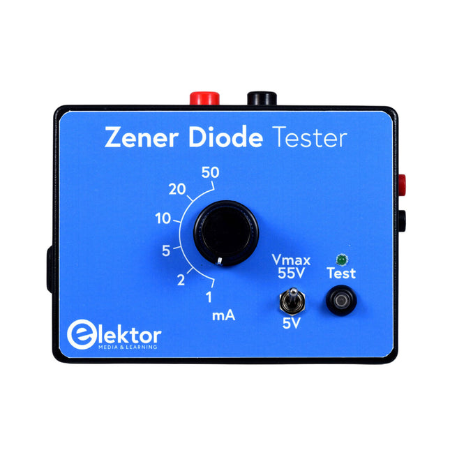
The Elektor Zener Diode Tester is essentially a constant-current source that can be switched in steps from 1 to 50 mA. It can be used to test Z-diodes up to a maximum of 54 V. Thanks to a 60-V step-up converter, the device can be powered by the usual 5 to 12 V.
The principle of this tester is straightforward. A Z-diode or other DUT (device under test, such as an LED) is biased by an adjustable current source. The voltage across the DUT can be measured with a multimeter. The voltage of most (small) Z-diodes is specified at a current of 5 mA. Depending on the application, the voltage at other currents can also be of interest. That is why six current settings are available: 1, 2, 5, 10, 20, and 50 mA. LEDs are often specified at a current of 20 mA.
What can be tested is:
Whether a Z-diode is defective (short circuit or high impedance).
Whether a Z-diode exhibits the correct Z-voltage.
How a Z-voltage changes with different currents.
What exact voltage is present at an integrated voltage reference.
Whether LEDs in a series chain differ in brightness (hence the 20 mA current).
What the current gain is for different base currents in (power) transistors.
The kit contains all parts listed in the bill of materials including PCB and enclosure.
Specifications
Supply voltage
5…12 V/2 A (USB-C)
Supply current (Itest = 50 mA)
1.1 A @ 5 V / 412 mA @ 12 V
Selectable currents
1, 2, 5, 10, 20, and 50 mA
Max. test voltage
>54 V @ Itest ≥1 mA
Max. output voltage
60 V @ Itest = 0 mA
Voltage limit at 5 V
4.5 V @ Itest = 1 mA / 5.18 V @ Itest = 50 mA
Enclosure dimensions
110 x 82 x 44 mm
PCB size
105.4 x 67.3 mm
Connections
4 mm banana sockets for multimeter
2 mm banana sockets for test clips
USB-C socket for power supply
Included
Resistors
R1 = 3.3 kΩ, 600 mW, 1%
R2 = 0.15 Ω, 1 W, 5%, LS 12.7 mm, ø 3.5 mm
R3, R8 = 180 Ω, 600 mW, 1%
R4, R6, R16 = 1 kΩ, 600 mW, 1%
R5, R19 = 47 kΩ, 600 mW, 1%
R7 = 3.9 kΩ, 1 W, 5%, LS 12.7 mm, ø 3.5 mm
R9, R10, R12 = 10 kΩ, 600 mW, 1%
R11, R13 = 100 Ω, 600 mW 1%
R14 = 249 Ω, 600 mW, 1%
R15 = 499 Ω, 600 mW, 1%
R17 = 2.49 kΩ, 250 mW, 1%
R18 = 4.99 kΩ, 250 mW, 1%
Capacitors
C1 = 470 uF / 35 V, 20%, Ir = 1.86 A, ø 12.5 mm, LS 5 mm, ESR = 0.038 Ω (Panasonic EEUTP1V471)
C2 = 1 uF / 100 V, 10%, X7R, LS 5 mm
C3 = 2.2 nF / 50 V, 10%, X7R, LS 5 mm
C4, C7 = 100 nF / 100 V, 10%, X7R, LS 5 mm
C5 = 100 uF / 100 V, 20%, ø 14 mm max., LS 5 mm
C6 = 1 nF / 100 V, 10%, X7R, LS 5 mm
Inductor
L1 = 100 uH, Irms = 2.4 A, Isat = 3.5 A, 0.09 Ω, radial, pitch 2.5/5/10 mm, ø 14 mm max. (Kemet SBC8-101-242)
Semiconductors
D1 = MUR120G, DO-41
D2, D4 = STPS3150RL, DO-201AD
D3 = Z-diode, 18 V, 1.3 W (BZX85C18)
D5 = Z-diode, 5.1 V, 0.5 W (1N5231B)
LED1 = LED in pushbutton S1
LED2 = LED, green, 3 mm
IC1 = MC34063, DIP-8
IC2 = LM4040BIZ-5.0/NOPB, TO-92 (TO-226AA-3)
IC3 = TL051CP, DIP-8
T1 = BC327.25, TO-92
T2 = STP40NF10L, TO-220
T3 = IRF9510PBF, TO-220
T4 = 2N7000, TO-92
Others
K1, K2, S1, S3 = 2-way screw terminal block, LS 3.5 mm, max. 1.5 mm²
connected to K1 = USB-C socket, 30 V/3 A, chassis mounted, wired, 9 x 16 mm
connected to K2 = Banana Connector, 2 mm, Socket, 60 VDC, Panel Mount, red (Multicomp 24.102.1)
connected to K2 = Banana Connector, 2 mm, Socket, 60 VDC, Panel Mount, black (Multicomp 24.102.2)
Test clip, red, 30 VAC/60 VDC (Hirschmann 931467101)
Test clip, black, 30 VAC/60 VDC (Hirschmann 931467100)
S1 = Pushbutton, panel mount, SPST-NO, 30 DC/100 mA, with red LED
S2 = Rotary Switch, 6 position, 2 pole, 30°, 250 V/150 mA
S3 = Toggle switch, panel mount, SPDT, solder lugs, 28 VDC
T2, T3 = Heat sink, 15°C/W, FK 214 SA-CB
Enclosure Hammond 1591XXSSBK, ABS, 110 x 82 x 44 mm
Knob for S2, round shaft 6 mm, ø 21 mm, with indicator line (Multicomp CP-LB21-6-6D)
4 x Self-tapping screw #4-1/4", carbon steel, pan head
Banana plug, red, 2 mm, 60 VDC (Multicomp 25.205.1)
Banana plug, black, 2 mm, 60 VDC (Multicomp 25.205.2)
Banana socket, black 4 mm, panel mount
Banana socket, red 4 mm, panel mount
for LED1, LED2 = Pin header, 1 x 2, vertical, pitch 2.54 mm
for LED1, LED2 = Pin socket, 1 x 2, vertical, pitch 2.54 mm
for T2, T3 = M3 screw, 10 mm, steel, pan head
2 x M3 washer, plain, steel
4 x M3 nut
for IC1, IC3 = DIP-8 socket
Wire, black, 0.25 mm² (24 AWG), stranded 14 x 0.15 mm, 1 m
Wire, red, 0.25 mm² (24 AWG), stranded 14 x 0.15 mm, 1 m
PCB 250772-1 v1.1
Links
Article
Elektor Labs
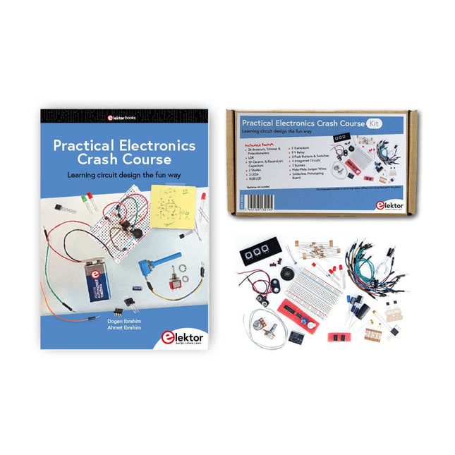
Getting started in electronics is not as difficult as you may think. With this bundle (book + kit of parts), you can explore and learn the most important electrical and electronics engineering concepts in a fun way by doing various experiments. You will learn electronics practically without getting into complex technical jargon and long calculations. As a result, you will be creating your own projects soon.
This kit contains the components required to build most of the detailed examples of the book on a breadboard and try them out for real.
The kit can, of course, also be used without the book for building other circuits and doing your own experiments.
Kit contents
1x 39 Ω, 1 W resistor
1x 47 Ω resistor
1x 180 Ω resistor
1x 330 Ω resistor
3x 1 kΩ resistor
1x 2.2 kΩ resistor
1x 3.9 kΩ resistor
1x 6.8 kΩ resistor
1x 10 kΩ resistor
1x 15 kΩ resistor
1x 22 kΩ resistor
1x 33 kΩ resistor
1x 47 kΩ resistor
1x 56 kΩ resistor
1x 82 kΩ resistor
1x 120 kΩ resistor
1x 680 kΩ resistor
2x 100 kΩ resistor
1x 10 kΩ trimmer
1x 10 kΩ linear potentiometer
1x 100 kΩ linear potentiometer
1x LDR
1x 1 nF ceramic capacitor
2x 10 nF ceramic capacitor
1x 100 nF ceramic capacitor
1x 1 µF, 25 V aluminium electrolytic capacitor
2x 10 µF, 25 V aluminium electrolytic capacitor
1x 100 µF, 25 V aluminium electrolytic capacitor
1x 470 µF, 25 V aluminium electrolytic capacitor
1x 1000 µF, 25 V aluminium electrolytic capacitor
1x RGB LED, Common-Cathode (CC)
1x 1N4148 small signal diode
1x 1N4733A 5.1 V, 1 W Zener diode
3x LED, red
2x BC337 NPN transistor
1x IRFZ44N N-channel MOSFET
2x NE555 timer
1x LM393 comparator
1x 74HCT08 quad AND gate
3x Tactile switch
2x SPDT switch
1x Relay, SPDT, 9 VDC
1x Active buzzer
1x Passive buzzer
50 cm Solid wire, 16 AWG, unjacketed
2x PP3 9 V battery clip
1x Breadboard
20x Jumper wire
This bundle contains:
Practical Electronics Crash Course Kit (valued at: €45)
Book: Practical Electronics Crash Course (normal price: €45)
Arduino-compatible, ESP32-controlled, 2-wheeled Balancing Robot
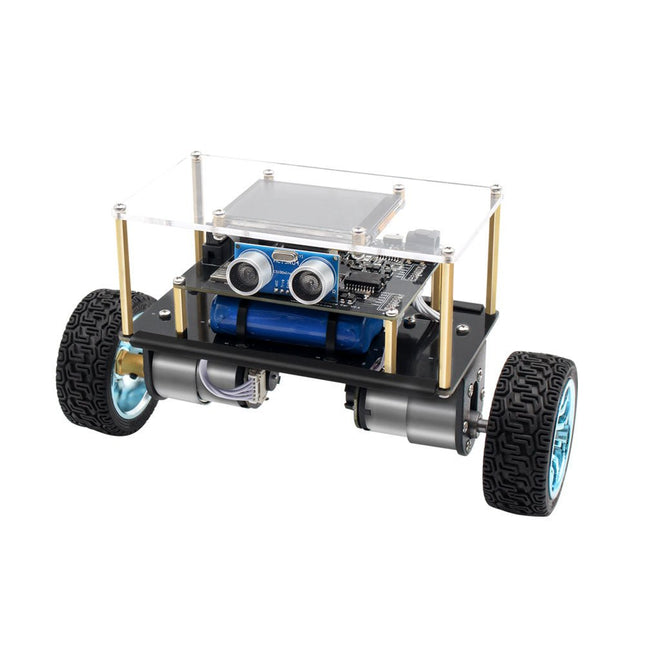
The Elektor Mini-Wheelie is an experimental autonomous self-balancing robot platform. Based on an ESP32-S3 microcontroller, the self-balancing robot is fully programmable using the Arduino environment and open-source libraries. Its wireless capabilities allow it to be controlled remotely over Wi-Fi, Bluetooth or ESP-NOW or to communicate with a user or even another robot.
An ultrasonic transducer is available for detecting obstacles. Its color display can be used for displaying cute facial expressions or, for the more down-to-earth users, cryptic debug messages.
The robot comes as a neat kit of parts that you must assemble yourself. Everything is included, even a screwdriver.
Note: The Mini-Wheelie is an educational development platform intended for learning, experimentation, and robotics development. It is not classified as a toy for children, and its features, documentation, and intended audience reflect this purpose. The product is aimed at students, educators, and developers who wish to explore robotics, programming, and hardware integration in an educational setting.
Specifications
ESP32-S3 microcontroller with Wi-Fi and Bluetooth
MPU6050 6-axis Inertial Measurement Unit (IMU)
Two independently controlled 12 V electric motors with tachometer
Ultrasonic transducer
2.9" TFT color display (320 x 240)
MicroSD card slot
Battery power monitor
3S rechargeable Li-Po battery (11.1 V/2200 mAh)
Battery charger included
Arduino-based open-source software
Dimensions (W x L x H): 23 x 8 x 13 cm
Included
1x ESP32-S3 Mainboard + MPU6050 module
1x LCD board (2.9 inch)
1x Ultrasonic sensor
1x Battery pack (2200 mAh)
1x Battery charger
1x Motor tyre kit
1x Case board
1x Acrylic board
1x Screwdriver
1x Protective strip
1x Flex cable B (8 cm)
1x Flex cable A (12 cm)
1x Flex cable C
4x Copper column A (25 mm)
4x Copper column B (55 mm)
4x Copper column C (5 mm)
2x Plastic nylon column
8x Screws A (10 mm)
24x Screws B (M3x5)
8x Nuts
24x Metal washers
2x Zip tie
1x MicroSD card (32 GB)
Downloads
Documentation
This bundle contains the popular Elektor Sand Clock for Raspberry Pi Pico and the new Elektor Laser Head Upgrade, offering even more options for displaying the time. Not only can you "engrave" the current time in sand, you can now alternatively write it on a glow-in-the-dark foil or create green drawings.
Contents of the bundle
Elektor Sand Clock for Raspberry Pi Pico (normal price: €50)
Elektor Laser Head Upgrade for Sand Clock (normal price: €35)
Elektor Sand Clock for Raspberry Pi (Raspberry Pi-based Eye Catcher)
A standard sand clock just shows how time passes. In contrast, this Raspberry Pi Pico-controlled sand clock shows the exact time by "engraving" the four digits for hour and minute into the layer of sand. After an adjustable time the sand is flattened out by two vibration motors and everything begins all over again.
At the heart of the sand clock are two servo motors driving a writing pen through a pantograph mechanism. A third servo motor lifts the pen up and down. The sand container is equipped with two vibration motors to flatten the sand. The electronic part of the sand clock consists of a Raspberry Pi Pico and an RTC/driver board with a real-time clock, plus driver circuits for the servo motors.
A detailed construction manual is available for downloading.
Features
Dimensions: 135 x 110 x 80 mm
Build time: approx. 1.5 to 2 hours
Included
3x Precut acrylic sheets with all mechanical parts
3x Mini servo motors
2x Vibration motors
1x Raspberry Pi Pico
1x RTC/driver board with assembled parts
Nuts, bolts, spacers, and wires for the assembly
Fine-grained white sand
Elektor Laser Head Upgrade for Sand Clock
The new Elektor Laser Head transforms the Sand Clock into a clock that writes the time on glow-in-the-dark film instead of sand. In addition to displaying the time, it can also be used to create ephemeral drawings. The 5 mW laser pointer, with a wavelength of 405 nm, produces bright green drawings on the glow-in-the-dark film. For best results, use the kit in a dimly lit room. Warning: Never look directly into the laser beam!
The kit includes all the necessary components, but soldering three wires is required.
Note: This kit is also compatible with the original Arduino-based Sand Clock from 2017. For more details, see Elektor Magazine 1-2/2017 and Elektor Magazine 1-2/2018.
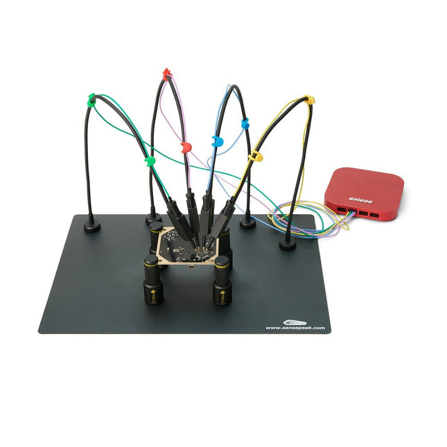
The SQ series of handsfree PCBite probes from Sensepeek are insulated, come with included color-coded cable holders and have a lower point of gravity making them even more stable compared with the original SP series of probes. All the loved features of handsfree measurement, exchangeable fine pitch spring tipped test needle and the minimalistic design is maintained to make traditional sized and handheld probes obsolete.
Features
All handsfree probes from Sensepeek makes instant measurements or long triggering sessions a breeze.
No more soldering wires to connect your probe or complicated tools to setup, just positioning the probe needle on any test point or component in the signal path and release.
Saves time and frustration during development, verification and repairs.
The minimalist design and the spring-loaded test needle makes it possible to simultaneously measure on fine pitch components and nearby signals.
Both length and weight of the SQ probes are perfectly balanced to be used with the included PCB holders and base plate which is a must for handsfree function.
The probe holder comes with a powerful magnet in the base, as for all PCBite probes and holders which makes the probe easy to place and reposition.
The SQ series of probes can be used handheld without the probe holder as they have an insulated grip but their full potential is used when measuring handsfree.
One side of the included baseplate is matte and the other is mirror polished. The mirror polished surface makes it easy to see components on the circuit board underside. For added protection during measurement the included insulation cover can be mounted on one of the surfaces.
Included
4x PCBite PCB holders
1x Set of yellow insulation washers for the PCB holders
1x Large Base plate (A4)
1x Insulation cover for the base plate (A4)
1x Micro fiber cloth
4x SQ10 probes and pin tipped test needles (black)
2x Banana to dupont test wires (red/black)
5x Dupont to dupont test wires
1x Set of cable holders (4 colors)
4x Extra test needles
Downloads
User guide (PCBite kit)
User guide (SQ10 probes)