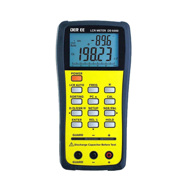
The DE-5000 is a smart, high-accurate, flexible and easy-to-use portable LCR meter. It features automatic LCR check, 4-wire Kelvin measurement, backlit display with 19999/1999 counts, multiple measurement modes and selectable test frequencies (100 Hz, 120 Hz, 1 kHz, 10 kHz or 100 kHz). The DE-5000 LCR meter is a practical helper for engineers or technicians.
Features
Auto L.C.R. check
Ls/Lp/Cs/Cp/Rs/Rp/DCR with D/Q/θ/ESR measurement
4-wire Kelvin measurement
20,000 / 2,000 counts display
Backlight
Relative mode
Series / Parallel modes
Components sorting function
Low battery indication
Auto power off
Specifications
Test frequency
100 Hz / 120 Hz / 1 kHz / 10 kHz / 100 kHz
Resistance range
20.000 Ω – 200.0 MΩ
DCR range
200.00 Ω – 200.0 MΩ
Capacitance range
200.00 pF – 20.00 mF
Inductance range
20.000 µH – 2.000 KH
Display (backlit LCD)
19999 / 1999 counts
Selectable tolerance
±0.25%, ±0.5%, ±1%, ±2%, ±5%, ±10%, ±20%
Power supply
9 V battery
Dimensions
188 x 95 x 52 mm
Weight
350 g (excluding battery)
Included
DE-5000 LCR meter
Alligator test lead case (TL-21)
AC/DC adaptor
Guard line (TL-23)
TL-22 SMD tweezers
9 V battery
Carrying case
Manual
Downloads
Datasheet
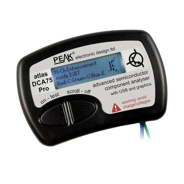
The DCA75 Pro is a great instrument that combines ease-of-use with amazing features. It can automatically identify a huge range of semiconductors, automatically identify pinouts and measure detailed parameters.
Features
Built-in graphics display (now backlit) to show detailed schematic of the component you're testing as well as pinout and measurement data
USB connectivity to allow curve tracing, data storage/retrieval and device matching on your Windows PC (Windows 7 and higher)
Single internal AAA alkaline cell for standalone operation
Component Support
Bipolar transistors (NPN/PNP inc Silicon/Germanium)
Darlington transistors (NPN/PNP)
Enhancement mode MOSFETs (N-Ch and P-Ch)
Depletion mode MOSFETs (N-Ch and P-Ch)
Junction FETs (N-Ch and P-Ch). Both symmetrical and asymmetrical types
Enhancement IGBTs (N-Ch and P-Ch)
Diodes and diode networks (2 and 3 lead types)
Zener diodes (up to about 9 V)
Voltage regulators (up to about 8 V)
LEDs and bi-colour LEDs (2 lead and 3 lead types)
Low power sensitive Triacs and Thyristors (<10 mA trigger and hold)
Measurements
BJT current gain (hFE)
BJT base emitter voltage (Vbe)
BJT collector leakage current
MOSFET on and off gate threshold voltages
MOSFET transconductance
JFET pinch-off voltage
JFET transconductance
JFET IDSS (drain current for Vgs=0)
IGBT on and off gate threshold voltages
IGBT transconductance
Voltage regulator output voltage
Voltage regulator quiescent current consumption
Voltage regulator drop-out voltage
Zener voltage
Diode forward voltage drop
Specifications
Analyzer type
Semiconductor components
Component detection
Automatic
Pinout detection
Automatic, connect any way round
Display type
Graphic LCD (now backlit)
Interface type
USB for optional PC connection
PC functions
Curve tracing (Windows 7 and higher)
Software
Included on USB drive for Windows 7 and higher
Battery
Single AAA cell (supplied)
Included
Peak Atlas DCA75 Pro
PC software on a USB Flash Drive for Windows 11, 10, 8, 7, XP
Micro USB cable
Fitted universal premium hook probes
AAA Alkaline battery
Downloads
Datasheet (EN)
User Guide (EN)
User Guide (IT)
Software Installation Guide (EN)
Software and Firmware Package
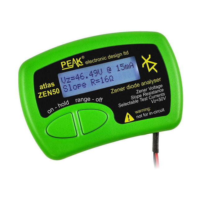
The Peak Atlas ZEN50 is ideal for testing Zener diodes (including avalanche diodes), transient suppressors, LEDs and LED strings. It generates constant current pulses (selectable from 2 mA, 5 mA, 10 mA and 15 mA) at voltages from 0 V to 50 V. So even high voltage Zeners or high voltage LED strings can be tested.
Test currents are supplied in narrow pulses to ensure that the component under test remains at a constant temperature.
The voltage of the part is displayed on the screen together with the test current and also a measure of the component's slope resistance (also known as dynamic impedance).
Specifications
Analyzer type
Zeners, LEDs, TVS etc
Test currents
2 mA, 5 mA, 10 mA, 15 mA
Voltage range
0.00 to 50.00 V
Slope resistance range
0 to 8000 Ohms
Battery type
Single AAA (supplied). Life typically 1400 ops
Test method
Triple pulse burst @ 10pps (typ)
Test current duty cycle
3%
Display type
Alphanumeric LCD (with backlight)
Included
Peak Atlas ZEN50 Zener Diode Analyzer
Fitted flexible test leads with gold plated crocs
Comprehensive illustrated user guide
AAA Alkaline battery
Downloads
Datasheet (EN)
User Guide (EN)
User Guide (FR)
User Guide (DE)
User Guide (IT)
The OWON SDS1102 is an affordable benchtop digital oscilloscope that combines solid performance with essential measurement features. This 2-channel oscilloscope offers a 100 MHz bandwidth, a 1 GS/s sampling rate, a 7-inch LCD display, and a 10 kpts memory depth, making it a practical choice for everyday electronics testing, troubleshooting, and education.
The SDS1102 features a simplified trigger system with level and edge triggering, making it easy to capture and analyze common signals. It is designed for applications that do not require deep memory or advanced trigger functions, offering a straightforward and cost-effective solution for basic signal analysis.
Features
Bandwidth: 100 MHz
2 channels
Sample rate: 1 GS/s
Ultra-thin body
7-inch high-res LCD
SCPI and LabVIEW supported
Specifications
Bandwidth
100 MHz
Horizontal Scale (s/div)
5 ns/div – 1000 s/div
Channel
2
Vertical Sensitivity
5 mV/div – 5 V/div (at input)
DC Gain Accuracy
3%
Vertical Resolution (A/D)
8 bits (2 channels simultaneously)
Input
Input Impedance
1 MΩ, 10 pF
Input Coupling
AC, DC, GND
Max Input Voltage
±400 V, CATI, CATII
Passive probes
х1; х10
Probe Attenuation Factor
х1; х10; х100; х1000
Trigger System
Trigger Mode
Auto, Normal, Single
Trigger Type
Edge, Video
Edge Trigger Source
CH1, CH2
Video Trigger
Sampling Type
Real-time
Sample Rate
1 GS/s
Equivalent Sample Rate
No
Wavelength
10K pts
Interpolation
sin(x)/x
Measurement and Mathematical Treatment System
Automatic Measurement
Vpp, Vavg, RMS, Frequency, Period, Vmax, Vmin, Vtop, Vbase, Width, Overshoot, Pre-shootRise time, Fall time, +Width, -Width, +Duty, -Duty, Delay A→B, Delay A→B, area, cycle area
Math Functions
Addition, Subtraction, Multiplication, Division, FFT
General Characteristics
Display type
7" color LCD
Display Resolution
800 x 480
Power
100-240 V, 45-440 Hz, <15 W
Dimensions
301 x 70 x 152 mm
Weight
1.1 kg
Included
1x OWON SDS1102 Oscilloscope
2x Oscilloscope probes
1x Probe adjust
1x Mains power cord
1x USB cable
1x CD-Rom
1x Quick guide
Downloads
Quick Guide
Manual
PC Software
SCPI Commands
Die heutige Regelungstechnik hat Verknüpfungspunkte mit fast jedem technischen Gebiet. Ihre Anwendungen reichen von der Elektrotechnik über die Antriebstechnik und den Maschinenbau bis hin zur Verfahrenstechnik. Will man nun die Regelungstechnik anhand der fachlichen Regeln dieser einzelnen Gebiete erklären, so müsste man von einem Regelungstechniker verlangen, jedes Fachgebiet, in dem er Regelungen vornehmen will, fundiert zu beherrschen. Dies ist aber bei dem heutigen Stand der Technik nicht möglich.
Bei der Regelung einer Antriebsaufgabe, einer Druck- oder einer Temperaturregelung tauchen Gemeinsamkeiten auf, die man mit einer einheitlichen Vorgehensweise beschreiben kann. Die Grundgesetze der Regelungstechnik gelten in gleicher Weise für alle Regelkreise, ganz unabhängig davon, wie verschieden sie im Einzelnen auch apparativ aufgebaut sein mögen.
Dieses Buch richtet sich an den Praktiker, der gründlicher in die Regelungstechnik eindringen möchte, auf ausschweifende theoretische Exkursionen in die Mathematik aber gerne verzichten kann.
Worauf es bei der Lösung von Regelungsaufgaben eigentlich ankommt, ist nicht die Kenntnis vieler Formeln und Rechenverfahren, sondern das Erfassen der Zusammenhänge im Regelkreis. Genau diese beschreibt das vorliegende Buch in anschaulicher Form.
Parallel zur Theorie wird die Praxis von regelungstechnischen Vorgängen mit den Simulations-Tools WinFACT und Multisim ausführlich erläutert. Hiermit lassen sich sehr einfach Versuche mit regelungstechnischen Modulen und umfangreichen Messinstrumenten simulieren, Fehler aufspüren und Lösungen für die Praxis finden. Nebenbei entsteht so ein fundiertes Grundlagenwissen.
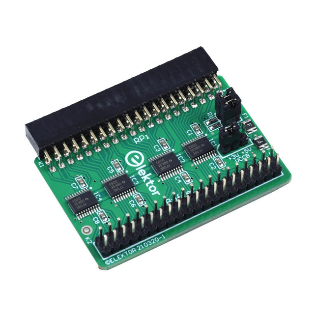
When you experiment with the Raspberry Pi on a regular basis and you connect a variety of external hardware to the GPIO port via the header you may well have caused some damage in the past. The Elektor Raspberry Pi Buffer Board is there to prevent this! The board is compatible with Raspberry Pi Zero, Zero 2 (W), 3, 4, 5, 400 and 500.
All 26 GPIOs are buffered with bi-directional voltage translators to protect the Raspberry Pi when experimenting with new circuits. The PCB is intended to be inserted in the back of Raspberry Pi 400/500. The connector to connect to the Raspberry Pi is a right angled 40-way receptacle (2x20). The PCB is only a fraction wider. A 40-way flat cable with appropriate 2x20 headers can be connected to the buffer output header to experiment for instance with a circuit on a breadboard or PCB.
The circuit uses 4x TXS0108E ICs by Texas Instruments. The PCB can also be put upright on a Raspberry Pi.
Downloads
Schematics
Layout
The Weller WT 1013 soldering station set includes the WT 1 supply unit, the WP 80 soldering iron and the WSR 201 safety rest. It is stackable and thus creates more space in the workplace. With an integrated usage sensor, the soldering tool switches off automatically.
Specifications
Channels
1
Voltage
230 V
Power
95 W
Display
Backlit LCD
Temperature range
50 °C - 450 °C
Temperature stability
±2 °C
Temperature accuracy
±9 °C
Fuse
0.5 A
Equipotential bonding
on
WT compatible
on
ESD-safe
on
Power cable
EMEA
Dimensions
149 x 138 x 101 mm
Weight (approx.)
1.9 kg
310 Schaltungen – das elfte Buch innerhalb der „Dreihunderter-Reihe“. 310 Schaltungen und neue Konzepte in einem Buch sind ein (fast) unerschöpflicher Fundus zu allen Bereichen der Elektronik: Audio & Video, Spiel & Hobby, Haus & Hof, Prozessor & Controller, Messen & Testen, PC & Peripherie, Stromversorgung & Ladetechnik sowie zu Themen, die sich nicht katalogisieren lassen.
310 Schaltungen – enthält viele komplette Problemlösungen, zumindest aber die Idee hierzu. Nicht zuletzt sind die 310 Schaltungen der Anstoß zu ganz neuen Überlegungen.
310 Schaltungen – sind eine Zusammenfassung der Beiträge aus den Halbleiterheften 2006 bis 2008. Die Halbleiterhefte sind die jährlichen Doppelausgaben Juli/August der Zeitschrift Elektor.
310 Schaltungen ist das Buch für alle, die kreativ mit der Elektronik umgehen; sei es im Beruf oder als Hobby.
311 Schaltungen – das zwölfte Buch innerhalb der „Dreihunderter-Reihe“. 311 Schaltungen und neue Konzepte in einem Buch sind ein (fast) unerschöpflicher Fundus zu allen Bereichen der Elektronik: Audio & Video, Spiel & Hobby, Haus & Hof, Prozessor & Controller, Messen & Testen, PC & Peripherie, Stromversorgung & Ladetechnik sowie zu Themen, die sich nicht katalogisieren lassen.
311 Schaltungen – enthält viele komplette Problemlösungen, zumindest aber die Idee hierzu. Nicht zuletzt sind die 311 Schaltungen der Anstoß zu ganz neuen Überlegungen.
311 Schaltungen – sind eine Zusammenfassung der Beiträge aus den Halbleiterheften 2009 bis 2011. Die Halbleiterhefte sind die jährlichen Doppelausgaben Juli/August der Zeitschrift Elektor.
311 Schaltungen ist das Buch für alle, die kreativ mit der Elektronik umgehen; sei es im Beruf oder als Hobby.
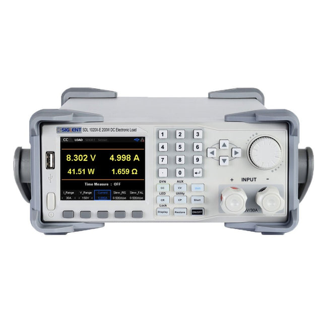
The Siglent SDL1020X-E DC Load leads with measurement resolution of 0.1 mV/0.1 mA and the base SDL1000X-E series resolution is 1 mV/1 mA and adjustable current rise times from 0.001 A/μs~2.5 A/μs. For remote communication and control, the SDL series includes S232/USB/LAN interface types. The SDL1020X-E delivers stability over a wide range of applications and can meet all kinds of testing requirements. including: Power, battery/handheld device design, industry, LED lighting, automotive electronics, and aerospace.
Features
SDL1020X-E (Single channel): DC 150 V/30 A, total power 200 W
4 static modes / Dynamic mode: CC/CV/CR/CP
CC Dynamic mode: Continuous, pulsed, toggled
CC Dynamic mode: 25 kHz, CP Dynamic mode: 12.5 kHz, CV Dynamic mode: 0.5 Hz
Measuring speed of voltage and current: up to 500 kHz
Adjustable current rise time range: 0.001 A/us~2.5 A/us
Min. readback resolution: 0.1 mV, 0.1 mA
Short-circuit, Battery test, CR-LED mode, and factory test functions
4-wire SENSE compensation mode function
List function supports editing as many as 100 steps
Program function supports 50 groups of steps
OCP, OVP, OPP, OTP and LRV protection
External analog control
Voltage, Current monitoring via 0-10 V
3.5 inch TFT-LCD display, capable of displaying multiple parameters and states simultaneously
Built-in RS232/USB/LAN communication interface, USB-GPIB module (optional)
Waveform trend chart and easy-to-use file storage and call functions
Includes PC software: Supports SCPI, LabView driver
Included
1x Siglent SDL1020X-E DC Programmable Load
1x Quick start guide
1x Guarantee Card
1x Power Cord
1x USB Cable
Downloads
Datasheet
Manual
Programming Guide
PC Software
High-quality soldering station with the most important tools and consumables, ideal for universal soldering applications.
Features
1-Channel Power Unit, digital, 70 W
Power unit, 1 channel with soldering iron WEP 70 and safety rest PH 70
70W solder iron with ergonomic handle and providing toolless tip change
ESD safe station, iron and heat-resistant silicon cable for safe handling
Using ET soldering tips
Standby mode and auto setback conserves energy, protects equipment
Password-protected to preserve settings
Specifications
Dimensions: 150 x 120 x 98 mm
Weight: 1.4 kg
Display: Digital LC Display
Temperature range: Adjustable from 100°C - 450°C (200°F - 850°F)
Voltage: 230 V
Channels: 1
Temperature range (depends on tool) °C: 100-450
Temperature range (depends on tool) °F: 200-850
Temperature accuracy °C: Average tip temperature can be „offset“ to +/- 5°C at idle with no load
Temperature accuracy °F: Average tip temperature can be „offset“ to +/- 9°F at idle with no load
Temperature stability °C: ±6
Temperature stability °F: ±10
Heat-up time (ca) in seconds (50-350°C / 120-660°F): 28 sec.
Heating output: 85 W
309 Schaltungen – das zehnte Buch innerhalb der „Dreihunderter-Reihe“. 309 Schaltungen und neue Konzepte in einem Buch sind ein (fast) unerschöpflicher Fundus zu allen Bereichen der Elektronik: Audio & Video, Spiel & Hobby, Haus & Hof, Prozessor & Controller, Messen & Testen, PC & Peripherie, Stromversorgung & Ladetechnik sowie zu Themen, die sich nicht katalogisieren lassen.
309 Schaltungen – enthält viele komplette Problemlösungen, zumindest aber die Idee hierzu. Nicht zuletzt sind die 309 Schaltungen der Anstoß zu ganz neuen Überlegungen.
309 Schaltungen – sind eine Zusammenfassung der Beiträge aus den Halbleiterheften 2003 bis 2005. Die Halbleiterhefte sind die jährlichen Doppelausgaben Juli/August der Zeitschrift Elektor.
309 Schaltungen ist das Buch für alle, die kreativ mit der Elektronik umgehen; sei es im Beruf oder als Hobby.