The OWON SDS1102 is an affordable benchtop digital oscilloscope that combines solid performance with essential measurement features. This 2-channel oscilloscope offers a 100 MHz bandwidth, a 1 GS/s sampling rate, a 7-inch LCD display, and a 10 kpts memory depth, making it a practical choice for everyday electronics testing, troubleshooting, and education.
The SDS1102 features a simplified trigger system with level and edge triggering, making it easy to capture and analyze common signals. It is designed for applications that do not require deep memory or advanced trigger functions, offering a straightforward and cost-effective solution for basic signal analysis.
Features
Bandwidth: 100 MHz
2 channels
Sample rate: 1 GS/s
Ultra-thin body
7-inch high-res LCD
SCPI and LabVIEW supported
Specifications
Bandwidth
100 MHz
Horizontal Scale (s/div)
5 ns/div – 1000 s/div
Channel
2
Vertical Sensitivity
5 mV/div – 5 V/div (at input)
DC Gain Accuracy
3%
Vertical Resolution (A/D)
8 bits (2 channels simultaneously)
Input
Input Impedance
1 MΩ, 10 pF
Input Coupling
AC, DC, GND
Max Input Voltage
±400 V, CATI, CATII
Passive probes
х1; х10
Probe Attenuation Factor
х1; х10; х100; х1000
Trigger System
Trigger Mode
Auto, Normal, Single
Trigger Type
Edge, Video
Edge Trigger Source
CH1, CH2
Video Trigger
Sampling Type
Real-time
Sample Rate
1 GS/s
Equivalent Sample Rate
No
Wavelength
10K pts
Interpolation
sin(x)/x
Measurement and Mathematical Treatment System
Automatic Measurement
Vpp, Vavg, RMS, Frequency, Period, Vmax, Vmin, Vtop, Vbase, Width, Overshoot, Pre-shootRise time, Fall time, +Width, -Width, +Duty, -Duty, Delay A→B, Delay A→B, area, cycle area
Math Functions
Addition, Subtraction, Multiplication, Division, FFT
General Characteristics
Display type
7" color LCD
Display Resolution
800 x 480
Power
100-240 V, 45-440 Hz, <15 W
Dimensions
301 x 70 x 152 mm
Weight
1.1 kg
Included
1x OWON SDS1102 Oscilloscope
2x Oscilloscope probes
1x Probe adjust
1x Mains power cord
1x USB cable
1x CD-Rom
1x Quick guide
Downloads
Quick Guide
Manual
PC Software
SCPI Commands
Highlights
Output Frequency (Sine): 100 MHz
Output Frequency (Square): 25 MHz
Channels: 2
Arbitrary Waveform Length: 16 Mpts
Features
Unique SiFi II (Signal Fidelity II) technology: generate the arbitrary waveforms point by point; recover the signal without distortion; sample rate accurate and adjustable; jitter of all the output waveforms (including Sine, Pulse, etc.) as low as 200 ps
16 Mpts memory depth per channel for arbitrary waveforms
Standard dual-channel with the same performance, equivalent to two independent signal sources
High frequency stability: ±1 ppm; low phase noise: -105 dBc/Hz
Built-in high-order harmonic generator (at most 8-order harmonics)
Built-in 7 digits/s, 240 MHz bandwidth full featured frequency counter
Up to 160 built-in arbitrary waveforms, covering the common signals in engineering application, medical electronics, auto electronics, math processing, and other various fields
Sample rate up to 250 MSa/s, vertical resolution 16 bits
Arbitrary waveform sequence editing function available; arbitrary waveforms also can be generated through the PC software
Various analog and digital modulation functions: AM, FM, PM, ASK, FSK, PSK, and PWM.
Standard waveform combine function, capable of outputting specified waveforms combined with the basic waveforms
Standard channel tracking function, when enabled, all the parameters of both channels are updated based on users' configurations
Standard interface: USB Host&Device and LAN (LXI Core 2011 Device); USB-GPIB function supported
4.3'' TFT
Included
1x Rigol DG2102 Function/Arbitrary Waveform Generator
1x Power cord
1x USB cable
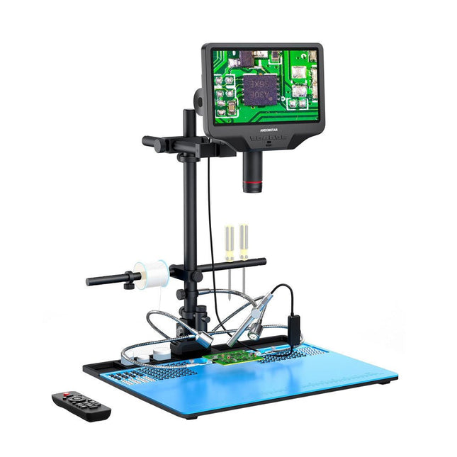
The Andonstar AD409 Max-ES boosts a high-quality metal lens and a unique UV filter design. Crafted from top-tier industrial-grade materials, it delivers unmatched precision and durability, ensuring a reliable product experience. The UV filter positioned in front of the metal lens blocks soldering heat, smoke, and dust, safeguarding the lens and making it perfect for soldering and maintenance professionals.
The AD409 Max-ES features an oversized Max station (46 x 37 x 47.5 cm) and an advanced tool set, expanding the soldering station area by 370%. This upgrade meets the demands of professional soldering tasks and provides ample workspace for larger projects.
The easy-to-use tool holder keeps tools within reach, ensuring they are always accessible. Additionally, the soldering helping hands with rotatable clamps simplify soldering and repair tasks, enhancing efficiency and convenience.
The endoscope offers an all-around 360° view. This allows for clear observation of components from all sides and inside pipes, eliminating blind spots and ensuring thorough inspections.
Features
High-quality Metal Lens and Unique UV Filter Design
New Max station
Easy-to-use Tool Holder and Soldering Helping Hands
Microscope with Endoscope All-around View 360°
Professional HDMI Digital Microscope supports Multiple Output Methods
8 Levels adjustable LEDs
Convenient Wireless Remote Control
Specifications
Screen size
10.1 inch (1280x800)
Image sensor
4 MP
Video output
UHD 2880x2160 (24fps)FHD 1920x1080 (60fps/30fps)HD 1280x720 (120fps)
Video format
MP4
Magnification
Up to 300 times (27 inch HDMI monitor)
Photo resolution
Max. 24 MP (5600x4200)
Photo format
JPG
Focus range
Min. 5 cm
Frame Rate
Max. 120fps
Video interface
HDMI
Storage
microSD card (up to 64 GB)
PC support
Windows, PC software with measurement
Mobile phone, tablet terminal support
Support WiFi connection and measurement
Power source
5 V DC
Light source
2 LEDs with the stand
Endoscope
Yes
Stand size
46 x 37 x 47.5 cm (18.1 x 14.6 x 18.7")
Included
1x Andonstar AD409 Max-ES Digital Microscope
1x Endoscope
1x Stand with 2 LEDs
1x UV filter (already assembled in the lens)
1x Soldering mat
1x Beam
1x Column
1x Tool holder
1x Soldering Helping Hands
1x Power adapter
1x Power cable
1x HDMI cable
1x USB cable
1x IR remote
1x Manual
Downloads
Manual
Software
The Siglent SDM3045X is a 4½ digit digital (66000 counts, sampling rate 150 Sa/s) multimeter incorporating a dual-display and is especially well suited for the needs of high-precision, multifunction and automatic measurement.
With its large 4.3" (10.9 cm) TFT color display (480x272 pixels), the menu navigation is very intuitive to use and very easy to read.
Features
Real 4½ digit (66000 counts) readings resolution
Up to 150 rdgs/s measurement speed
True-RMS AC Voltage and AC Current measuring
1 GB NAND flash size, mass storage configuration files and data files
Built-in cold terminal compensation for thermocouple
With easy, convenient and flexible PC software: EasyDMM
Standard interface: USB Device, USB Host, LAN
USB & LAN remote interfaces support common SCPI command set. Compatible with other popular DMMs on the market.
Application Fields
Research Laboratory
Development Laboratory
Detection and Maintenance
Calibration Laboratory
Automatic Production Test
Measurement Functions
DC Voltage: 600 mV – 1000 V
DC Current: 600 μA – 10 A
AC Voltage: True-RMS, 600 mV – 750 V
AC Current: True-RMS, 60 mA – 10 A
2/4-Wire Resistance: 600 Ω – 100 MΩ
Capacitance: 2 nF – 10000 μF
Continuity Test: Range is fixed at 2 kΩ
Diode Test: Adjustable range is 0-4 V
Frequency Measurement: 20 Hz – 500 KHz
Period Measurement: 2 μs – 0.05 s
Temperature: Support for TC and RTD sensor
Max, Min, Average, Standard Deviation, dBm/dB, Relative Measurement, Pass/Fail, Histogram, Trend Chart
Specifications
DC voltage
200 mV, 2 V, 20 V, 200 V, 1000 V
DC current
200 μA, 2 mA, 20 mA, 200 mA, 2 A, 10 A
AC voltage
True-RMS, 200 mV, 2 V, 20 V, 200 V, 750 V
AC current
True-RMS, 20 mA, 200 mA, 2 A, 10 A
2/4-wire resistance
200 Ω, 2 K, 20 K, 200 K, 2 M, 10 M, 100 MΩ
Capacitance
2 nF, 20 nF, 200 nF, 2 μF, 20 μF, 200 μF, 10000 μF
Connectivity Test
Range fixed 2 KΩ
Diode test
Range fixed 2 V
Frequency
20 Hz ~ 1 MHz
Period
1 μs ~ 0.05 s
Temperature
Support thermocouple, RTD temperature sensor
Maximum input voltage
1000 V
Configuration Interface
USB Device, USB Host, LAN
Included
1x Siglent SDM3065X Multimeter
2x Multimeter Probes
1x Power Cord
1x USB Cable
1x Quick Start Guide
Downloads
User Manual
Datasheet
Remote Manual
Service Manual
Pull Down Lever For Highest Score!
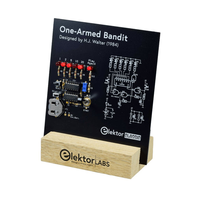
This Elektor Circuit Classic from 1984 shows a playful application of CMOS 400x series logic ICs in combination with LEDs, a highly popular combination at the time. The project imitates a spinning-digit type slot machine.
The Game
To play the game, first agree on the number of rounds. Player 1 actuates the switch lever as long as desired and releases it. The LEDs then show the score which is the sum of the 50-20-10-5 digits lit up. If the Play Again! LED lights, Player 1 has another, “free” round. If not, it’s Player 2’s turn. The players keep tab of their scores, and the highest score wins.
Features
LEDs Indicate Score
Multi-Player and Play Again!
Elektor Heritage Circuit Symbols
Tried & Tested by Elektor Labs
Educational & Geeky Project
Through-Hole Parts Only
Included
Printed Circuit Board
All Components
Wooden Stand
Bill of Materials
Resistors (5%, 250 mW)
R1,R2,R3,R4 = 100kΩ
R5,R6,R7,R8,R9,R10 = 1kΩ
Capacitors
C1 = 4.7nF, 10%, 50V, 5mm
C2 = 4.7μF, 10%, 63V, axial
C3,C4 = 100nF, 10 %, 50V, ceramic X7R, 5mm
Semiconductors
LED1-LED6 = red, 5mm (T1 3/4)
IC1 = 74HC4024
IC2 = 74HC132
Miscellaneous
S1 = switch, toggle, 21mm lever, SPDT, momentary
S2 = switch, tactile, 24V, 50mA, 6x6mm
S3 = switch, slide, SPDT
IC1,IC2 = IC socket, DIP14
BT1 = PCB-mount CR2032 battery retainer clip
Desktop Stand
PCB 230098-1
Not included: BT1 = CR2032 coin cell battery
This bundle includes the Red Pitaya STEMlab 125-14 PRO Gen 2 Starter Kit and the new book "Experimenting with Red Pitaya STEMlab Gen 2".
The Red Pitaya STEMlab 125-14 PRO Gen 2 Starter Kit is a powerful and flexible platform for signal processing, data acquisition, and electronic measurement applications. Designed for engineers, developers, researchers, and educators, this kit provides everything required to start building advanced measurement and control systems.
At the core of the kit is the STEMlab 125-14 PRO Gen 2 board, an upgraded and ultra-lightweight development platform. Powered by the Xilinx Zynq-7010 SoC with 512 MB of RAM, it combines FPGA programmability with ARM processing power to enable high-performance instrumentation and custom signal-processing solutions.
The board offers 14-bit ADC and DAC resolution, a 125 MS/s sampling rate, an input range of ±20 V, and up to 60 MHz bandwidth. Its improved low-noise analog front-end, USB-C connectivity, and compact design make it suitable for demanding applications such as RF development, radar systems, photonics research, software-defined radio (SDR), and industrial automation.
The Starter Kit includes all essential accessories for immediate use: a microSD card with preinstalled operating system, power supply, Ethernet cable for remote access, two 100 MHz oscilloscope probes, and SMA-to-BNC adapters for flexible signal connections.
The Red Pitaya STEMlab 125-14 PRO Gen 2 Starter Kit is an excellent platform for rapid prototyping, FPGA development, measurement instrumentation, and advanced electronics experimentation.
Features
14-bit ADC and DAC resolution
125 MS/s sampling rate
±20 V input range
Up to 60 MHz bandwidth
Xilinx Zynq-7010 SoC (FPGA + ARM processor)
512 MB RAM
Low-noise analog front- and back-ends
Applications
RF development and testing
Radar and wireless systems
Software-defined radio (SDR)
Photonics and optical research
Industrial automation and control systems
Signal analysis and instrumentation
Rapid prototyping of electronic measurement systems
Specifications
Processor
Dual-core ARM Cortex-A9
FPGA
AMD Xilinx Zynq-7010 SoC
RAM
512 MB (4 Gb)
Storage
microSD card (up to 32 GB)
Operating System
Linux-based Red Pitaya OS
ADC Resolution
14-bit
DAC Resolution
14-bit
Bandwidth
60 MHz (DC)
Sampling Rate
125 MS/s
Analog Input Channels
2
Analog Output Channels
2
Input Voltage Range
±1 V (LV) / ±20 V (HV)
Input Impedance
1 MΩ / 10 pF
Output Voltage Range
±1 V
Ethernet
1x Gigabit Ethernet (RJ45)
USB
2x USB-C 2.0 (for power and console)
Digital I/O
16x GPIO (3.3 V)
Communication Interfaces
I²C, SPI, UART, CAN
Power Supply
5 V/3 A via USB-C
Dimensions
106.8 x 60.0 x 17.9 mm
Included
1x Red Pitaya STEMlab 125-14 PRO Gen 2 board
2x 100 MHz oscilloscope probes
2x SMA-to-BNC adapters
1x microSD card with preinstalled OS
1x USB-C Power supply
1x Ethernet cable
Downloads
Documentation
Schematics
Book: Experimenting with Red Pitaya STEMlab Gen 2
With this new book, Red Pitaya goes beyond a versatile board. It becomes a powerful laboratory instrument for precision measurement, analysis, and control.
From the fundamentals of electronic project development, monitoring, control, and design to testing, this book walks you step-by-step through everything you need to know to harness the full potential of Red Pitaya hardware and software.
The book presents real-time, FPGA-based projects that are developed on a PC using the Vivado environment, then transferred to the Red Pitaya for execution and testing.
You will learn about enhanced performance, expanded I/O capabilities, improved FPGA features, and advanced connectivity options that open up new frontiers for precision measurement, monitoring, and control in your embedded applications.
Inside the book you will discover:
A deep dive into Red Pitaya architecture and hardware design
Electronic experiments using Red Pitaya for measurement and monitoring
Hands-on projects using the Python programming language
Practical guidance for FPGA programming using Red Pitaya
Red Pitaya FPGA projects using the Verilog HDL under Vivado IDE
Practical design of electronic projects including measurement and testing
Step-by-step examples that bridge theory and real-world implementation
Whether you are designing your own electronic circuits, developing signal analysis tools, or creating real-time control or monitoring systems, this book provides you the knowledge and confidence you need to fully learn and customize the Red Pitaya platform.
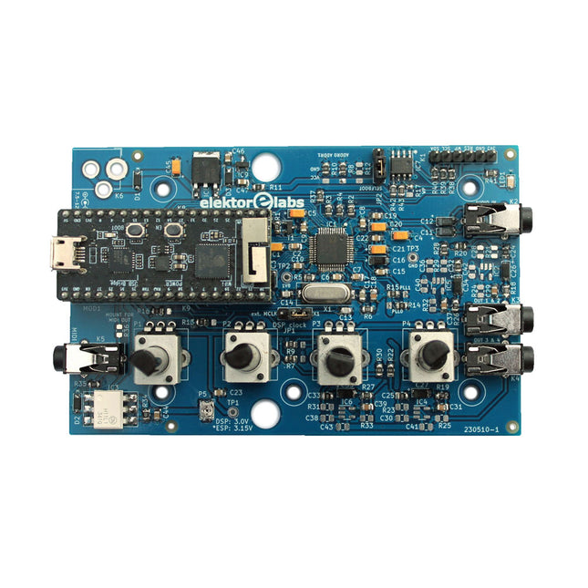
The Elektor Audio DSP FX Processor combines an ESP32 microcontroller and an ADAU1701 Audio DSP from Analog Devices. Besides a user-programmable DSP core, the ADAU1701 has high-quality analog-to-digital and digital-to-analog converters built-in and features an I²S port. This makes it suitable as a high-quality audio interface for the ESP32.
Programs for the ESP32 can be created with Arduino, Platform IO, CMake or by using the Espressif IDF in another way. Programs for the ADAU7101 audio DSPs are created with the free visual programming tool SigmaStudio by dragging and dropping pre-defined algorithm blocks on a canvas.
Applications
Bluetooth/Wi-Fi audio sink (e.g. loudspeaker) & source
Guitar effect pedal (stomp box)
Music synthesizer
Sound/function generator
Programmable cross-over filter for loudspeakers
Advanced audio effects processor (reverb, chorus, pitch shifting, etc.)
Internet-connected audio device
DSP experimentation platform
Wireless MIDI
MIDI to CV converter
and many more...
Specifications
ADAU1701 28-/56-bit, 50-MIPS digital audio processor supporting sampling rates of up to 192 kHz
ESP32 32-bit dual-core microcontroller with Wi-Fi 802.11b/g/n and Bluetooth 4.2 BR/EDR and BLE
2x 24-bit audio inputs (2 V RMS, 20 kΩ)
4x 24-bit audio outputs (0.9 V RMS, 600 Ω)
4x Control potentiometer
MIDI in- and output
I²C expansion port
Multi-mode operation
Power supply: 5 V DC USB or 7.5-12 V DC (barrel jack, center pin is GND)
Current consumption (average): 200 mA
Included
1x ESP32 Audio DSP FX Processor board (assembled)
1x ESP32-PICO-KIT
2x Jumpers
2x 18-pin headers (female)
4x 10 KB potentiometers
Downloads
Documentation
GitHub
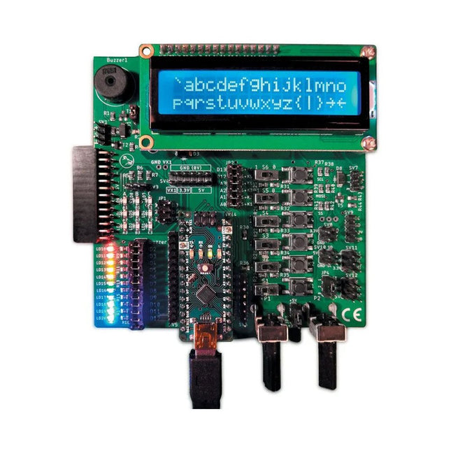
The Elektor Arduino Nano MCCAB Training Board contains all the components (incl. Arduino Nano) required for the exercises in the "Microcontrollers Hands-on Course for Arduino Starters", such as light-emitting diodes, switches, pushbuttons, acoustic signal transmitters, etc. External sensors, motors or assemblies can also be queried or controlled with this microcontroller training system.
Specifications (Arduino Nano MCCAB Training Board)
Power Supply
Via the USB connection of the connected PC or an external power supply unit (not included)
Operating Voltage
+5 Vcc
Input Voltage
All inputs
0 V to +5 V
VX1 and VX2
+8 V to +12 V (only when using an external power supply)
Hardware periphery
LCD
2x16 characters
Potentiometer P1 & P2
JP3: selection of operating voltage of P1 & P2
Distributor
SV4: Distributor for the operating voltagesSV5, SV6: Distributor for the inputs/outputs of the microcontroller
Switches and buttons
RESET button on the Arduino Nano module 6x pushbutton switches K1 ... K6 6x slide switches S1 ... S6 JP2: Connection of the switches with the inputs of the microcontroller
Buzzer
Piezo buzzer Buzzer1 with jumper on JP6
Indicator lights
11 x LED: Status indicator for the inputs/outputs LED L on the Arduino Nano module, connected to GPIO D13 JP6: Connection of LEDs LD10 ... LD20 with GPIOs D2 ... D12
Serial interfacesSPI & I²C
JP4: Selection of the signal at pin X of the SPI connector SV12 SV9 to SV12: SPI interface (3.3 V/5 V) or I²C interface
Switching output for external devices
SV1, SV7: Switching output (maximum +24 V/160 mA, externally supplied) SV2: 2x13 pins for connection of external modules
3x3 LED matrix(9 red LEDs)
SV3: Columns of the 3x3 LED matrix (outputs D6 ... D8) JP1: Connection of the rows with the GPIOs D3 ... D5
Software
Library MCCABLib
Control of hardware components (switches, buttons, LEDs, 3x3 LED matrix, buzzer) on the MCCAB Training Board
Operating Temperature
Up to +40 °C
Dimensions
100 x 100 x 20 mm
Specifications (Arduino Nano)
Microcontroller
ATmega328P
Architecture
AVR
Operating Voltage
5 V
Flash Memory
32 KB, of which 2 KB used by bootloader
SRAM
2 KB
Clock Speed
16 MHz
Analog IN Pins
8
EEPROM
1 KB
DC Current per I/O Pins
40 mA on one I/O pin, total maximum 200 mA on all pins together
Input Voltage
7-12 V
Digital I/O Pins
22 (6 of which are PWM)
PWM Output
6
Power Consumption
19 mA
Dimensions
18 x 45 mm
Weight
7 g
Included
1x Elektor Arduino Nano Training Board MCCAB
1x Arduino Nano
MDP-P906 has a built-in cooling fan, and maximum output power of up to 300 W, which meets a wider range of testing needs and application scenarios. Through 2.4 GHz wireless communication, it can be connected to MDP-M01 Smart Digital Monitor module to realize the free combination of multiple channels of 300 W per channel.
MDP-P906 has the index, stability and reliability comparable to a professional power supply. It can output pure current, and provide powerful functions such as programmable output, timing output, timing control, automatic compensation, boost mode, etc., making itself a real cost-effective, smart and customized programmable linear DC power supply.
MDP-P906 adopts a precision CNC machined aluminum alloy shell, with fine workmanship, novel, mini and beautiful appearance, it completely subverts the rigid image of traditional desktop power supply. With stackable modular design and wireless communication function, MDP-P906 can work independently or paired, both on the workbench, and be carried out for on-site maintenance. MDP-P906 is a perfect solution for electronic engineer, especially field application engineers to meet different needs of power sources.
Built-in silent cooling fan, instant cooling, ensure a stable and efficient output!
Smart linear compensation, constant voltage & constant current
Positive & negative output, series boost, parallel current sharing
Applications
Universal tests and teaching experiments in R&D laboratory
Maintenance of digital products
Property verification and fault diagnosis of devices and circuits
Emergency power supply for model airplanes and vehicles
Power supply testing of RF and microwave circuits or modules
Quality control and quality inspection
Supply purified power for high-accuracy digital-analog hybrid circuits and Hi-Fi audio devices
Specifications
Input
DC 4.2-30 V/14 A (Max)QC 3.0/PD2.0, 20 V/5 A (Max)
Output
0-30 V/0-10 A, 300 W (Max)
Conversion efficiency
95%
Output resolution
10 mV/2 mA, up to 1 mV/1 mA via Display Control module
Output accuracy
0.03%+5 mV0.05%+2 mV
Adjustment rate
Load adjustment rate <±0.01%Power adjustment rate <±0.01%
Ripple and noise
<250 uVrms, 3 mVpp; 2 mArms
Transient response
<4 uS
Safety protections
Input over-voltage, under-voltage, reverse connection protection, output over-current, back-flow protection and over-temperature protection
Others
Automatically shut-down and enter micro-power modeSupport USB firmware upgrade
Dimensions
112 x 66 x 20 mm
Weight
181 g
Included
1x MDP-P906 Digital Power Supply
2x Output Cable
1x User Manual
Downloads
User Manual v1.1
Firmware v1.32
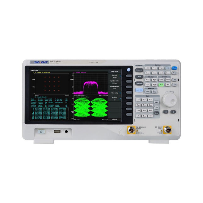
The Siglent SSA3075X Plus spectrum analyzer is a powerful and flexible tool for RF signal and network analysis. With a frequency range of 7.5 GHz, the analyzer delivers reliable automatic measurements and multiple modes of operation: spectrum analyzer the base, optional functions include RF power measurement, vector signal modulation analysis, reflection measurement, and EMI test.
Applications include broadcast monitoring/evaluation, site surveying, S-parameter measurement, analog/digital modulation analysis, EMI pre-compliance test, research and development, education, production, and maintenance.
Features
Spectrum Analyzer Frequency Range from 9 kHz to 7.5 GHz
–165 dBm/Hz Displayed Average Noise Level (Typ.)
–98 dBc/Hz. @ 10 kHz Offset Phase Noise (1 GHz, Typ.)
Level Measurement Uncertainty <0.7 dB (Typ.)
1 Hz Minimum Resolution Bandwidth (RBW)
Preamplifier (Std.)
Tracking Generator (incl. free of charge)
Analog and Digital Signal Modulation Analysis Mode (opt.)
Reflection Measurement Kit (opt.)
EMI Filter and Quasi-Peak Detector Kit (opt.)
Advanced Measurement Kit (opt.)
10.1-inch Multi-Touch Screen , Mouse and Keyboard supported
Web Browser Remote Control on PC and Mobile Terminals and File Operation
Specifications
SSA3015X Plus
SSA3021X Plus
SSA3032X Plus
SSA3075X Plus
Frequency Range
9 kHz ~ 1.5 GHz
9 kHz ~ 2.1 GHz
9 kHz ~ 3.2 GHz
9 kHz ~ 7.5 GHz
Resolution Bandwidth
1 Hz ~ 1 MHz
1 Hz ~ 1 MHz
1 Hz ~ 1 MHz
1 Hz ~ 3 MHz
Phase Noise
<–99 dBc/Hz
<–98 dBc/Hz
<–98 dBc/Hz
<–98 dBc/Hz
Total Amplitude Accuracy
<1.2 dB
<0.7 dB
<0.7 dB
<0.7 dB
Display Average Noise Level
–156 dBm/Hz
–161 dBm/Hz
–161 dBm/Hz
–165 dBm/Hz
Included
Siglent SSA3075X Plus spectrum analyzer
USB cable
Power cord
Quick start guide
Downloads
Datasheet
Manual
Documentation
Firmware
Specifications
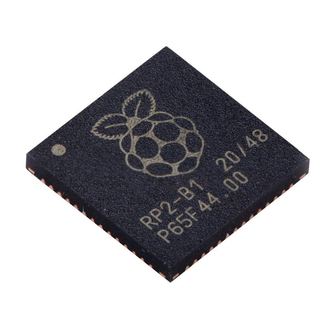
Dual ARM Cortex-M0+ @ 133 MHz
264 kB on-chip SRAM in six independent banks
Support for up to 16 MB of off-chip Flash memory via dedicated QSPI bus
DMA controller
Fully-connected AHB crossbar
Interpolator and integer divider peripherals
On-chip programmable LDO to generate core voltage
2x on-chip PLLs to generate USB and core clocks
30x GPIO pins, 4 of which can be used as analogue inputs
Peripherals
2x UARTs
2x SPI controllers
2x I²C controllers
16x PWM channels
USB 1.1 controller and PHY, with host and device support
8x PIO state machines
What you'll get
10x bare RP2040 chips
The Seeed Studio RF Explorer WSUB1G+ is a powerful, high-performance digital spectrum analyzer covering frequencies from 50 kHz to 1 GHz. The Slim model features a robust design, a more conveniently positioned USB connector on the side, and a larger internal battery capacity.
Features
Internal LNA amplifier and selectable attenuator
Low frequency support from 50 KHz covering LF, MF, HF, VHF and UHF up to 960 Mhz
New HELP and SET buttons to improve user interface and configuration selection with 2-clicks
Wide band coverage to all popular sub-1 Ghz bands, including FM, TV and DTV, ISM, RFID, GSM, etc.
Ideal choice for HAM bands from 160 m to 33 cm
Pocket size and light weight
Solid metal case
Spectrum Analyzer mode with Peak Max and Hold, Normal, Overwrite and Averaging modes
High capacity internal Lithium battery for 20hs+ of continuous run, rechargeable by USB
Multi-platform Windows/Linux/MacOS Open Source software and API libraries
Can be extended with internal Expansion Modules for additional band and functionality
Specifications
Frequency band: 0.05 MHz – 960 MHz
Frequency span: 0.1 MHz – 960 MHz
Internal selectable LNA 25 dB gain
Internal selectable Attenuator 30 dB
Graphics LCD 128 x 64 pixels, great visibility outdoors
Support included for Windows, Linux and MacOS X
Backlight for great visibility indoor
Internal Lithium Ion 1800 mA/h rechargeable battery
Standard SMA 50 Ω connector
Wideband 144/433 MHz dual band telescopic antenna included
UHF 400-900 MHz rubber duck articulated antenna included
Amplitude resolution: 0.5 dBm
Dynamic range: -125 dBm to 10 dBm
Absolute Max input power: +30 dBm
Average noise level (typical LNA): -125 dBm
Frequency stability and accuracy (typical): ±10 ppm
Amplitude stability and accuracy (typical): ±2 dBm
Frequency resolution: 1 kHz
Resolution bandwidth (RBW): Automatic 2.6 kHz to 600 kHz
Included
1x Seeed Studio RF Explorer WSUB1G+ Slim Spectrum Analyzer
1x Mini USB cable
1x Dual band 144/430 MHz Telescopic antenna
1x UHF 400-900 Mhz antenna
1x EVA case