Book: Mastering the Arduino Uno R4
Based on the low-cost 8-bit ATmega328P processor, the Arduino Uno R3 board is likely to score as the most popular Arduino family member, and this workhorse has been with us for many years. Eleven years later, the long-overdue successor, the Arduino Uno R4, was released. It is built around a 48 MHz, 32-bit Arm Cortex-M4 microcontroller and provides significantly expanded SRAM and Flash memory. Additionally, a higher-precision ADC and a new DAC are added to the design. The Uno R4 board also supports the CAN Bus with an interface.
Two versions of the board are available: Uno R4 Minima, and Uno R4 WiFi. This book is about using these new boards to develop many different and interesting projects with just a handful of parts and external modules. All projects described in the book have been fully tested on the Uno R4 Minima or the Uno R4 WiFi board, as appropriate.
The project topics include the reading, control, and driving of many components and modules in the kit as well as on the relevant Uno R4 board, including
LEDs
7-segment displays (using timer interrupts)
LCDs
Sensors
RFID Reader
4x4 Keypad
Real-time clock (RTC)
Joystick
8×8 LED matrix
Motors
DAC (Digital-to-analog converter)
LED matrix
WiFi connectivity
Serial UART
CAN bus
Infrared controller and receiver
Simulators
… all in creative and educational ways with the project operation and associated software explained in great detail.
Arduino Uno R4 WiFi
The Arduino Uno R4 is powered by the Renesas RA4M1 32-bit ARM Cortex-M4 processor, providing a significant boost in processing power, memory, and functionality. The WiFi version comes with an ESP32-S3 WiFi module in addition to the RA4M1, expanding creative opportunities for makers and engineers.
The Arduino Uno R4 runs at 48 MHz, which provides a 3x increase over the popular Uno R3. Additionally, SRAM has been upgraded from 2 kB to 32 kB, and flash memory from 32 kB to 256 kB to support more complex projects. Responding to community feedback, the USB port is now USB-C, and the maximum power supply voltage has been raised to 24 V with an enhanced thermal design. The board includes a CAN bus and an SPI port, enabling users to reduce wiring and perform parallel tasks by connecting multiple shields. A 12-bit analog DAC is also provided on the board.
Specifications
Microcontroller
Renesas RA4M1 (ARM Cortex-M4)
USB
USB-C
Programming Port
Pins
Digital I/O Pins
14
Pins
Analog input pins
6
DAC
1
RTC
1
PWM pins
6
Communication
UART
1x
I²C
1x
SPI
1x
Qwiic I²C connector
1x
CAN
1x CAN Bus
Power
Circuit operating voltage
5 V
Input voltage (VIN)
6-24 V
DC Current per I/O Pin
8 mA
Clock speed
Main core
48 MHz
Memory
RA4M1
256 kB Flash, 32 kB RAM
LED Matrix
12 x 8 (96 red LEDs)
Dimensions
68.9 x 53.4 mm
Downloads
Datasheet
Schematics
This bundle contains:
Book: Mastering the Arduino Uno R4 (normal price: €45)
Arduino Uno R4 WiFi (normal price: €30)
Projects with Arduino, ESPHome, Home Assistant, and Raspberry Pi & Co.
This e-book contains various example projects, beginning with an introduction to electronics. It also explains how to install Home Assistant on a Raspberry Pi, how to use indoor climate sensors for temperature and humidity, how to implement the MQTT protocol and other interfaces, and how to use ESPHome to integrate sensors and actuators into Home Assistant. Numerous video tutorials complement the book.
Fundamentals of electrical engineering
The book begins with an introduction to electrical engineering. You will learn the basics of voltage, current, resistors, diodes and transistors.
Arduino and microcontrollers
A complete section is dedicated to the Arduino Uno. You will get to know the structure, write your first programs and work on practical examples.
Home Assistant and automation
You will learn how to set up Home Assistant on a Raspberry Pi and how to use automations, scenes and devices. In addition, Zigbee, MQTT and ESP-NOW – important technologies for home automation – will be discussed.
ESP8266, ESP32 and ESP32-CAM
The popular ESP microcontrollers are covered in detail. A theoretical introduction is followed by practical projects that show you how to get the most out of these devices.
Sensors and actuators
The book explains the functionality and application of numerous sensors such as temperature and humidity sensors, motion detectors and RFID readers. For actuators, stepper motors, e-ink displays, servo motors and much more are covered. There are practical application examples for all devices.
ESPHome
This chapter shows you how to integrate sensors and actuators into Home Assistant without any programming effort. You will be guided step by step through the setup with ESPHome.
LEDs and lighting technology
In this chapter, you will learn about different types of LEDs and how they can be used. The basics of lighting technology are also explained.
Node-RED
A whole chapter is dedicated to Node-RED. You will learn the basics of this powerful tool and be guided step by step through its setup and use.
Integrated Circuits (ICs)
In electronics, there are numerous ICs that make our lives easier. You will get to know the most important ones and apply your knowledge in practical projects.
Professional programming
Advanced topics such as the correct use of buttons, the use of interrupts and the use of an NTP server for time synchronisation are covered in detail in this chapter.
Downloads
GitHub
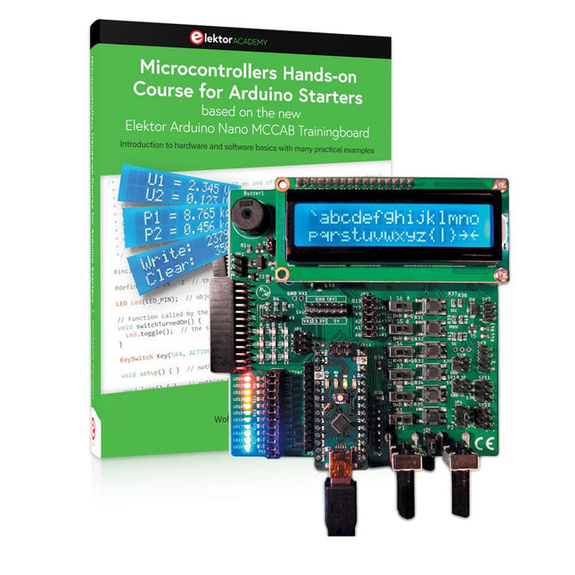
Realize your own projects with the Elektor Arduino Nano MCCAB Training Board
The microcontroller is probably the most fascinating subfield of electronics. Due to the multitude of functions, it combines on its chip, it is a universal multi-tool for developers to realize their projects. Practically every device of daily use today is controlled by a microcontroller. However, for an electronic layman, realizing his own ideas with a microcontroller has so far remained a pipe dream due to its complexity. The Arduino concept has largely simplified the use of microcontrollers, so that now even laymen can realize their own electronics ideas with a microcontroller.
Book & Hardware in the Bundle: 'Learning by Doing'
This book, which is included in the bundle, shows how you can realize your own projects with a microcontroller even without much experience in electronics and programming languages. It is a microcontrollers hands-on course for starters, because after an overview of the internals of the microcontroller and an introduction to the programming language C, the focus of the course is on the practical exercises. The reader acquires the necessary knowledge by 'learning by doing': in the extensive practical section with 12 projects and 46 exercises, what is learned in the front part of the book is underpinned with many examples. The exercises are structured in such a way that the user is given a task to solve using the knowledge built up in the theoretical part of the book. Each exercise is followed by a sample solution that is explained and commented on in detail, which helps the user to solve problems and compare it with his own solution.
Arduino IDE
The Arduino IDE is a software development environment that can be downloaded for free to your own PC and that contains the entire software package needed for your own microcontroller projects. You write your programs ('apps') with the IDE’s editor in the C programming language. You translate them into the bits and bytes that the microcontroller understands using the Arduino IDE's built-in compiler, and then load them into the microcontroller's memory on the Elektor Arduino MCCAB Nano Training Board via a USB cable.
Query or control external sensors, motors or assemblies
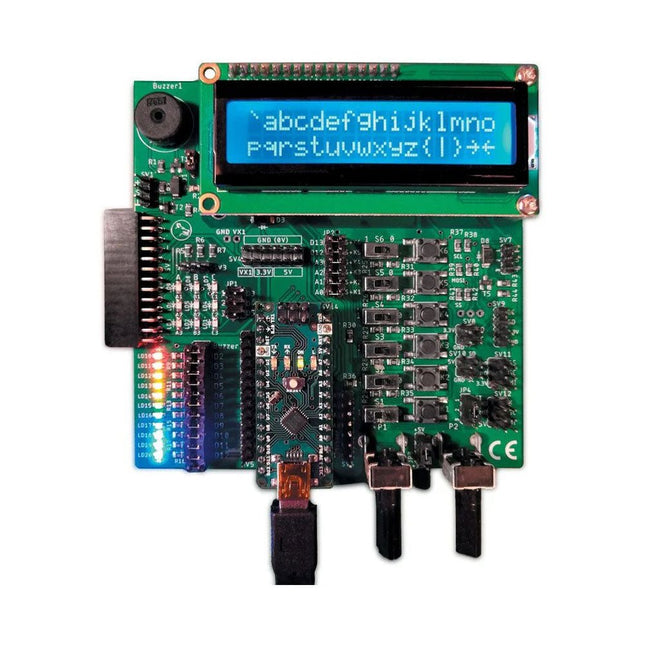
In addition to an Arduino Nano microcontroller module, the Elektor Arduino Nano MCCAB Training Board contains all the components required for the exercises, such as light-emitting diodes, switches, pushbuttons, acoustic signal transmitters, etc. External sensors, motors or assemblies can also be queried or controlled with this microcontroller training system.
Specifications (Arduino Nano MCCAB Training Board)
Power Supply
Via the USB connection of the connected PC or an external power supply unit (not included)
Operating Voltage
+5 Vcc
Input Voltage
All inputs
0 V to +5 V
VX1 and VX2
+8 V to +12 V (only when using an external power supply)
Hardware periphery
LCD
2x16 characters
Potentiometer P1 & P2
JP3: selection of operating voltage of P1 & P2
Distributor
SV4: Distributor for the operating voltagesSV5, SV6: Distributor for the inputs/outputs of the microcontroller
Switches and buttons
RESET button on the Arduino Nano module 6x pushbutton switches K1 ... K6 6x slide switches S1 ... S6 JP2: Connection of the switches with the inputs of the microcontroller
Buzzer
Piezo buzzer Buzzer1 with jumper on JP6
Indicator lights
11 x LED: Status indicator for the inputs/outputs LED L on the Arduino Nano module, connected to GPIO D13 JP6: Connection of LEDs LD10 ... LD20 with GPIOs D2 ... D12
Serial interfacesSPI & I²C
JP4: Selection of the signal at pin X of the SPI connector SV12 SV9 to SV12: SPI interface (3.3 V/5 V) or I²C interface
Switching output for external devices
SV1, SV7: Switching output (maximum +24 V/160 mA, externally supplied) SV2: 2x13 pins for connection of external modules
3x3 LED matrix(9 red LEDs)
SV3: Columns of the 3x3 LED matrix (outputs D6 ... D8) JP1: Connection of the rows with the GPIOs D3 ... D5
Software
Library MCCABLib
Control of hardware components (switches, buttons, LEDs, 3x3 LED matrix, buzzer) on the MCCAB Training Board
Operating Temperature
Up to +40 °C
Dimensions
100 x 100 x 20 mm
Specifications (Arduino Nano)
Microcontroller
ATmega328P
Architecture
AVR
Operating Voltage
5 V
Flash Memory
32 KB, of which 2 KB used by bootloader
SRAM
2 KB
Clock Speed
16 MHz
Analog IN Pins
8
EEPROM
1 KB
DC Current per I/O Pins
40 mA on one I/O pin, total maximum 200 mA on all pins together
Input Voltage
7-12 V
Digital I/O Pins
22 (6 of which are PWM)
PWM Output
6
Power Consumption
19 mA
Dimensions
18 x 45 mm
Weight
7 g
Included
Elektor Arduino Nano MCCAB Training Board
Arduino Nano
Book: Microcontrollers Hands-on Course for Arduino Starters
This complete ESP32 microcontroller programming course features a textbook, a component kit, hands-on projects, and a comprehensive online course with simulations. It is ideal for step-by-step learning of embedded systems programming with Arduino using a practical, hands-on approach.
A Practical Introduction to Embedded Systems with the ESP32
This course is designed for people who are new to embedded systems and looking for a structured, example-driven way to get started.
A kit of parts comprising LEDs and resistors, switches, sensors and actuators, displays, a breadboard and wires, and more is included. These are used in the course to illustrate example applications.
No prior experience with Arduino or embedded development is required. Each section features hands-on examples and mini projects designed to reinforce key concepts and inspire deeper exploration. By the end of the course, you’ll be able not only to reproduce the examples but also to build on them with your own ideas and applications.
What Will You Learn?
Microcontroller programming with the ESP32 using the Arduino IDE
Working with Digital I/O, read buttons and encoders, control LEDs and relays
Read analog inputs, voltages, and analog sensors
Generating analog output signals and PWM
Use serial communication like UART, I²C and SPI to control displays and read digital sensors and SD cards
Managing time
Working with interrupts
Real-time sensor input and control via buttons, LEDs, and displays
Control actuators like relays and servo motors
Who Is It For?
Students and self-learners exploring embedded systems
Makers and IoT enthusiasts looking to improve their hardware skills
Educators and trainers seeking ready-to-teach material
What's Inside the Box?
Access to the full course on the Elektor Academy Pro Learning Platform
ESP32 microcontroller board + USB cable
Book: Programming Microcontrollers in C/C++ Using Arduino
Downloadable project files for every module
Component Box:
2× LED, red, 5 mm
LED, green, 5 mm
3× Resistor, 470 Ω, 0.25 W
LDR
Potentiometer, 10 kΩ, linear
Pushbutton
Rotary encoder module
Relay module
DHT22 Humidity & Temperature Sensor
TM1637-compatible 4-digit 7-segment display
MPU-6050 IMU with headers
SSD1306-compatible I²C OLED display
Micro SD card adapter with header
Buzzer
SG90 Micro Servo
ILI9341-compatible SPI 240×320 TFT display
20× Jumper wires
Breadboard
All Programming Courses (and differences in content)
Course
Arduino
Raspberry Pi Pico with Arduino C/C++
ESP32 with Arduino C/C++
Raspberry Pi Pico with MicroPython
ESP32 with MicroPython
Online Course
Access to Arduino Course
Access to Pico with Arduino C/C++ Course
Access to ESP32 with Arduino C/C++ Course
Access to Pico with MicroPython Course
Access to ESP32 with MicroPython Course
Board
Uno R3
Raspberry Pi Pico
ESP32
Raspberry Pi Pico
ESP32
Book
Programming Microcontrollers in C/C++ Using Arduino
Programming Microcontrollers in C/C++ Using Arduino
Programming Microcontrollers in C/C++ Using Arduino
Programming Microcontrollers in MicroPython
Programming Microcontrollers in MicroPython
Kit
40-piece Component Box
40-piece Component Box
40-piece Component Box
40-piece Component Box
40-piece Component Box
With the JOY-iT PS1440-C-Pro, you get a programmable laboratory power supply that delivers DC voltages ranging from 0.01 to 60 V and DC currents from 0.01 to 24 A at the voltage output.
The intuitive control panel allows you to program, store, and recall up to 9 different DC voltage settings. You can also configure individual protection and limiting functions—such as overvoltage protection. All settings are easily adjusted via the keypad and/or rotary control and are clearly shown on the high-resolution 2.4" color display.
For enhanced connectivity, the PS1440-C-Pro includes an RS485 interface for robust, long-distance communication. This makes it ideal for complex setups where signal stability, noise immunity, and reliable data transfer are critical. The included connector ensures a secure connection, improving the overall reliability and performance of your laboratory equipment setup.
Features
Complete device ready for immediate use
RS485 interface
Battery charging function
Values can be entered conveniently via keypad
Over current & over voltage protection adjustable
Integrated RTC, NTC temperature sensor
Included detailed documentation in English, German & French
Specifications
Input voltage
230 V
Output voltage
060 V
Output current
0-24 A
Output power
0-1440 W
Input voltage accuracy
±1% +5 digits
Output voltage accuracy
±0.3% +3 digits
Output current accuracy
±0.5% +5 digits
Battery voltage
±0.5% +3 digits
Input voltage measurement resolution
0.01 V
Output voltage measurement resolution
0.01 V
Current measurement resolution
0.01 V
Battery voltage measurement resolution
0.01 V
Response time in constant voltage mode
2 ms @ 0.1-5 A
Load regulation in constant voltage mode
±0.1% +2 digits
Load regulation in constant current mode
±0.1% +3 digits
Measuring range electric charge
0-9999.99 Ah
Measuring range energy
0-9999.99 Wh
Statistical errors in electric charge & energy
±2%
Output ripple
100 mV VPP @ 12 V150 mV VPP @ 24 V
Sensor temperature detection range
−10~100°C (0-200°F)
Sensor temperature detection accuracy
±3°C (±6°F)
Working mode
Step-down operation
Screen brightness setting
Level 0-5, 6 levels in total
Permissible working temperature
−10~40°C (0-104°F)
Dimensions
170 x 93 x 340 mm
Included
JOY-iT PS1440-C Power Supply
2-pin connector for RS485 interface
Power cord
Manual
Downloads
Datasheet
MODBUS Protocol
PC Software
Driver for Windows
High-Performance LoRa Communication Device
The Elecrow ThinkNode M5 is a compact, portable LoRa communication device designed for off-grid messaging, location sharing, and outdoor use. Powered by an ESP32-S3 processor and an SX1262 LoRa chip, it comes pre-installed with Meshtastic firmware and can be configured conveniently via Bluetooth using the official Meshtastic app.
The integrated multi-GNSS module supports GPS, GLONASS, BeiDou, and QZSS for reliable positioning and location sharing. Messages and device information are displayed on the energy-efficient 1.54-inch e-paper screen, while the built-in 1,200 mAh rechargeable battery enables extended mobile operation.
With its integrated LoRa antenna, compact housing, RTC, and support for both Meshtastic and MeshCore firmware, the ThinkNode M5 is a practical communication solution for hiking, camping, remote locations, and emergency situations where conventional mobile networks are unavailable.
Features
LoRa communication
Multi-GNSS positioning
1,200 mAh rechargeable battery
1.54-inch e-paper display
Built-in RTC
Compatible with MeshCore
Compatible with Meshtastic
Specifications
Main Processor (ESP32-S3)
CPU/SoC
Xtensa 32-bit LX7 dual-core processor, clocked at up to 240 MHz
System Memory
512 KB SRAM, 8 MB PSRAM
Storage
4 MB Flash, 384 KB ROM
Firmware
Meshtastic firmware is fully compatible, and the signal is transmitted in LoRa mode
EPD (Electronic Paper Display)
Display Size
1.54 inch EPD (monochrome Ink screen)
Display Materials
E-lnk (Electronic Ink)
Resolution
200 x 200
Driver Chip
SSD1681 (via SPI or I²C interface)
Global Fresh Time
2s
Wireless Communication
Bluetooth
Bluetooth Low Energy and Bluetooth 5.0 (phone configuration)
LoRa
SX1262 LoRa Module, EU 868 MHz(external antenna)
Hardware
Interfaces
USB-C, RP-SMA
Function
GPS Location (GPS, GLONASS, BeiDou, QZSS), EPD Display, RTC, USB 2.0, PMU power management (built-in 1200 mAh lithium battery), buzzer, etc.
Button
Knob Switch, Function Button, Page Turn Button, GPS Switch, Reset Button
LED Indicator
Power supply, GPS/LoRa indication
Others
Power Input
5 V/1 A, supports USB or lithium battery power supply
Power consumption
The maximum working current is about 340 mA (CPU + LoRa module), and the low power consumption is about 34 uA
Operating Temperature
-10~50°C
Storage Temperature
-20~60°C
Relative humidity
10-95%, @ 40°C (non-condensing)
Enclosure
ABS Plastic
Dimensions
82 x 51.6 x 26.3 mm
Weight
81 g
Included
1x Elecrow ThinkNode M5
1x LoRa antenna
1x USB-C cable
1x Manual
Downloads
Manual
Elektor GREEN en GOLD leden kunnen deze uitgave hier downloaden.
Nog geen lid? Klik hier om een lidmaatschap af te sluiten.
Een stroombron voor het testen van Z-diodesControle van Z-diodes van 1 tot 54 V bij 1 tot 50 mA
ESD polsbandtesterEen testapparaat met indicatie voor ‘goed’, ‘grensgeval’ en ‘afgekeurd’
Testapparaat voor de respons op piekbelastingen van voedingenEen generator voor repeterende stapsgewijze belasting voor laboratoriumvoedingen
Euclidische sequencer zonder microcontrollerTriggerpatronen en CV-sequenties met eenvoudige CMOS-logica
LED-knipperlicht voor heksystemen en meer, inclusief geluidssignaal
Printen nodig? De Elektor PCB-service staat voor u klaar
Tandenborstel-timerMet een kleine PIC
Een contactloos magnetisch combinatieslotMet de AS5600 rotatie-positie sensor
Batterijgevoede ruisarme voorversterkervoor dynamische microfoons
Het Arduino Nano testLabMeten, sturen en regelen
Rhythmische basverlichtingBenadruk het ritme van je muziek
Low-cut filterGeen risico op audio-terugkoppeling op uw systeem
Nauwkeurige 1 Hz blokgolfgenerator voor breadboardsEen betrouwbare klokpuls op basis van CMOS
555 onderstebovenDutycycles tot nul
Van Halfgeleidergids tot Circuit Specials65 jaar innovatie op het gebied van elektronica
Elektrische isolatieCAN-interface met digitale isolator en voedingsmodule
SpongillatorEen sponsgebaseerde oscillator
Echte willekeurige getallengeneratorMet geïntegreerde chi-kwadraattoets
3D-viewer voor HTML-pagina'sEenvoudig en vrijwel zonder code
Programmeren met TLScriptEen scripttaal voor metingen, tests en besturing
Schakelingsontwerp: tips van experts
FeedbackWat is het en waarom is het belangrijk?
Eén board, eindeloze ideeën: Arduino UNO QVan retro-gaming tot realtime milieumonitoring
Hoe u een donut-antenne repareert
Standby-KillerEen echte aan/uit-schakelaar voor uw tv
Batterijen testenBatterijen meten met de Arduino Nano
Voeding voor audioversterkersEen goede voeding zonder netbrom
HF prototype printplatenMaak zelf snel een prototype printplaat
Type 3-overspanningsbeveiligingEen type 3-overspanningsbeveiliging voor uw gevoelige apparatuur
IoT-kamerthermostaat boardMet een op ESP32-C3/S3 gebaseerde Xiao MCU-module
Van star naar slimFlexibele en gedrukte elektronica, tussen visie en industriële realiteit
Touch-GUI voor ESP32 en Raspberry & cografische gebruikersinterface met de LittlevGL-bibliotheek
“Niet zomaar een project”vraaggesprek met Gábor Kiss-Vámosi, ontwikkelaar van LittlevGL
Capaci-metermet tweecijferig LED-display in dekatron-stijl
Hoe... een mechanisch contact of schakelaar ontdendereneen schakelaar is open of gesloten – toch?
Developer's Zonetips & trucs, vakkunstigheden en andere nuttige informatie
Uitbreidbaar milieumonitorsysteempubliceert gegevens op IoT-platforms
Multitasking met de ESP32Multitasking met de ESP32 taakgeoriënteerd programmeren met FreeRTOS en de Arduino IDE
Interactiefcorrecties & updates || vragen & antwoorden
Autoverlichting tunenlegaal, illegaal – maakt wél uit!
Review Toolcraft digitaal soldeerstation
Arduino Pro IDEeen eerste indruk
Twee warmtebeeldcamera’s vergeleken
Uit het leven gegrepende inrichting van een lab en werkplaats
Monsanto MAN1 LED-displayvreemde onderdelen
Theetimereen experiment met energy harvesting
Eenfase 1 kW AC-motorsturingdrie bedrijfsmodi: perioderegeling, fase-afsnijding en fase-aansnijding
Snel 3,5'-touchscreen voor de Raspberry Pipresteert beter voor hetzelfde geld
Oost West Lab Besteen blik in het allerheiligste, waar onbevoegden geen toegang hebben...
Eerste stappen met RISC-Vhet LoFive-board onder de loep
LoRa-Tracker: een uitdaging voor het labproblemen en oplossingen bij de ontwikkeling van elektronica
Met de vos in het IoT (2)aanmelden in het Sigfox-netwerk
Alle begin......hoeft niet zo moeilijk te zijn
Analoge elektronica ontwerpencase-study #1 – deel 1: MEMS-microfoon... test-een-twee-drie
Wie het kleine niet eertuit de ideeënbus van Elektor
In het kort: teksten voor microcontrollersspaar geheugen met compressie
In de schijnwerpers: de autonome autooverzicht van de stand van de techniek
Leidende start-ups en innovatoren over “Innovation 4.0” in München
Lego Electronic anno 1968elektronisch speelgoed fascineert na 50 jaar nog steeds
Beyond ElectronicsThe MX3D Bridge Senses the City
Hexadoku
The Elektor Arduino Nano MCCAB Training Board contains all the components (incl. Arduino Nano) required for the exercises in the "Microcontrollers Hands-on Course for Arduino Starters", such as light-emitting diodes, switches, pushbuttons, acoustic signal transmitters, etc. External sensors, motors or assemblies can also be queried or controlled with this microcontroller training system.
Specifications (Arduino Nano MCCAB Training Board)
Power Supply
Via the USB connection of the connected PC or an external power supply unit (not included)
Operating Voltage
+5 Vcc
Input Voltage
All inputs
0 V to +5 V
VX1 and VX2
+8 V to +12 V (only when using an external power supply)
Hardware periphery
LCD
2x16 characters
Potentiometer P1 & P2
JP3: selection of operating voltage of P1 & P2
Distributor
SV4: Distributor for the operating voltagesSV5, SV6: Distributor for the inputs/outputs of the microcontroller
Switches and buttons
RESET button on the Arduino Nano module 6x pushbutton switches K1 ... K6 6x slide switches S1 ... S6 JP2: Connection of the switches with the inputs of the microcontroller
Buzzer
Piezo buzzer Buzzer1 with jumper on JP6
Indicator lights
11 x LED: Status indicator for the inputs/outputs LED L on the Arduino Nano module, connected to GPIO D13 JP6: Connection of LEDs LD10 ... LD20 with GPIOs D2 ... D12
Serial interfacesSPI & I²C
JP4: Selection of the signal at pin X of the SPI connector SV12 SV9 to SV12: SPI interface (3.3 V/5 V) or I²C interface
Switching output for external devices
SV1, SV7: Switching output (maximum +24 V/160 mA, externally supplied) SV2: 2x13 pins for connection of external modules
3x3 LED matrix(9 red LEDs)
SV3: Columns of the 3x3 LED matrix (outputs D6 ... D8) JP1: Connection of the rows with the GPIOs D3 ... D5
Software
Library MCCABLib
Control of hardware components (switches, buttons, LEDs, 3x3 LED matrix, buzzer) on the MCCAB Training Board
Operating Temperature
Up to +40 °C
Dimensions
100 x 100 x 20 mm
Specifications (Arduino Nano)
Microcontroller
ATmega328P
Architecture
AVR
Operating Voltage
5 V
Flash Memory
32 KB, of which 2 KB used by bootloader
SRAM
2 KB
Clock Speed
16 MHz
Analog IN Pins
8
EEPROM
1 KB
DC Current per I/O Pins
40 mA on one I/O pin, total maximum 200 mA on all pins together
Input Voltage
7-12 V
Digital I/O Pins
22 (6 of which are PWM)
PWM Output
6
Power Consumption
19 mA
Dimensions
18 x 45 mm
Weight
7 g
Included
1x Elektor Arduino Nano Training Board MCCAB
1x Arduino Nano
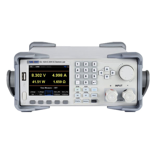
The Siglent SDL1020X-E DC Load leads with measurement resolution of 0.1 mV/0.1 mA and the base SDL1000X-E series resolution is 1 mV/1 mA and adjustable current rise times from 0.001 A/μs~2.5 A/μs. For remote communication and control, the SDL series includes S232/USB/LAN interface types. The SDL1020X-E delivers stability over a wide range of applications and can meet all kinds of testing requirements. including: Power, battery/handheld device design, industry, LED lighting, automotive electronics, and aerospace.
Features
SDL1020X-E (Single channel): DC 150 V/30 A, total power 200 W
4 static modes / Dynamic mode: CC/CV/CR/CP
CC Dynamic mode: Continuous, pulsed, toggled
CC Dynamic mode: 25 kHz, CP Dynamic mode: 12.5 kHz, CV Dynamic mode: 0.5 Hz
Measuring speed of voltage and current: up to 500 kHz
Adjustable current rise time range: 0.001 A/us~2.5 A/us
Min. readback resolution: 0.1 mV, 0.1 mA
Short-circuit, Battery test, CR-LED mode, and factory test functions
4-wire SENSE compensation mode function
List function supports editing as many as 100 steps
Program function supports 50 groups of steps
OCP, OVP, OPP, OTP and LRV protection
External analog control
Voltage, Current monitoring via 0-10 V
3.5 inch TFT-LCD display, capable of displaying multiple parameters and states simultaneously
Built-in RS232/USB/LAN communication interface, USB-GPIB module (optional)
Waveform trend chart and easy-to-use file storage and call functions
Includes PC software: Supports SCPI, LabView driver
Included
1x Siglent SDL1020X-E DC Programmable Load
1x Quick start guide
1x Guarantee Card
1x Power Cord
1x USB Cable
Downloads
Datasheet
Manual
Programming Guide
PC Software
Diese Ausgabe steht allen GOLD- und GREEN-Mitgliedern auf der ElektorMagazine-Website zum Download bereit!
Sie sind noch kein Mitglied? Hier klicken!
PbMonitor v1.0Ein Batterieüberwachungssystem für USV und Energiespeicher
Solarladeregler mit MPP-TrackingTeil 1: Grundlagen eines Solarreglers für Insel-Anlagen
B-Feld-Integrationsmagnetometer mit selbstgebauten Sensoren
Präzise, richtig oder genau?Ihre Messgeräte müssen alles sein!
AD7124 – Ein Präzisions-ADC in der PraxisHinweise für die Sensor-Signalaufbereitung
PID-RegelungswerkzeugOptimieren Sie ganz einfach Ihre Parameter
embedded world 2025
Aller Anfang ......muss nicht schwer sein: Klangeinstellung!
Academy Pro BoxBook + Online Course + Hardware
Milliohmmeter-AdapterNutzen Sie die Präzision Ihres Multimeters!
Der nächste Meilenstein bei HalbleiternWeiter in Richtung 1,4 nm
Steckverbinder in DurchstecktechnikDas Beste aus zwei Welten: THR
FrequenzzählerPortabel und mit automatischer GPS-Kalibrierung
Analoge MessgeräteBemerkenswerte Bauteile
Stand-alone-QuarztesterWie genau ist Ihre Taktquelle?
Preiswerter I²C-TesterSchließen Sie I²C-Chips direkt an Ihren PC an
Aus dem Leben gegriffenWer das Kleine nicht ehrt...
2025: Eine Odyssee in die KIDie transformativen Auswirkungen auf die Softwareentwicklung
Projekt 2.0Korrekturen, Updates und Leserbriefe
Standalone-MIDI-Synthesizer mit Raspberry PiTeil 2: Setup mit Intelligenz aufwerten
Nortonisierter Wien-Brücken-OszillatorKleine Änderungen führen zu bedeutenden Verbesserungen
10-Cent-Controller in der PraxisRISC-V-Mikrocontroller CH32V003 und MounRiver Studio ausprobiert
Audio-Player mit FPGA und EqualizerTeil 2: Lautstärkeregelung, erweitertes Mischen und ein Web-Interface
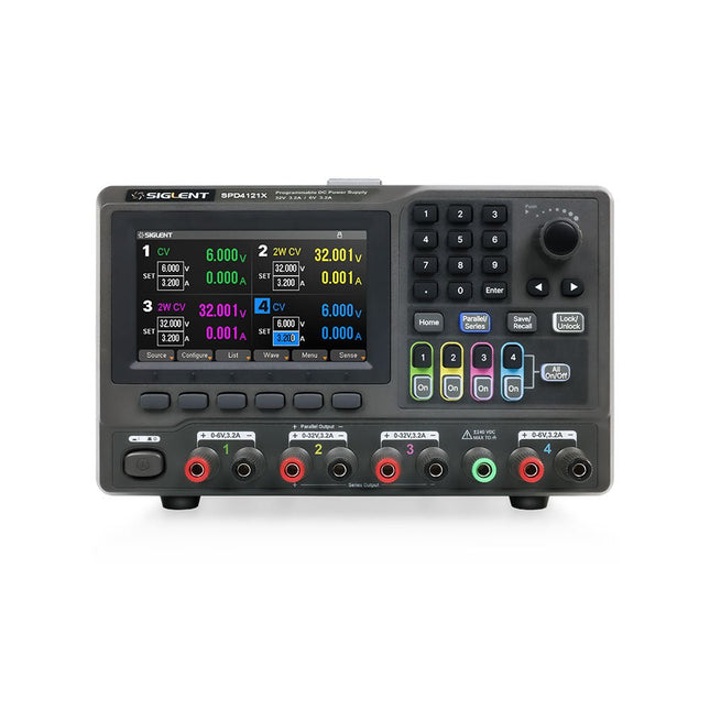
The Siglent SPD4121X is a 4-channel DC Linear Programmable Power Supply equipped with a 4.3-inch TFT-LCD display, friendly human-machine interface, and excellent performance indicators. Real-time waveform display provides engineers with an informative user interface.
SPD4121X offers a total output power of 285 W with a resolution of 1 mV/1 mA. The maximum voltage and current for each channel are as follows:
CH1: 15 V/1.5 A
CH2: 12 V/10 A
CH3: 12 V/10 A
CH4: 15 V/1.5 A
Features
Rated output power: 285 W
Rated voltage: 32 V, 12 V, 30 V
Up to four high-precision power supplies with independent controllable outputs, supporting CH2 and CH3 series and parallel connections
Clear graphical interface with waveform and timer display modes
5-digit voltage and current display with minimum resolution of 1 mV, 1 mA
Fast output response time: <50us
The high current channel support remote voltage compensation sense function. The maximum compensation voltage is 0.6 V
Overvoltage protection and overcurrent protection or safe and accurate operation
Equipped with a 4.3-inch TFT-LCD display (480 x 272 resolution)
USB and LAN standard communication
USB-GPIB module is optional
Excellent channel density with up to 4 channels in a 3U half rack package
Internal data storage for setups and parameters
Embedded Web Server with instrument communication that doesn’t require software installation
Fully SCPI programming command set support as well as a LabView driver for remote control and system automation
Specifications
SPD4323X
SPD4121X
SPD4306X
Channel Output
CH1: Voltage 0 to 6 V Current 0 to 3.2 ACH2: Voltage 0 to 32 V Current 0 to 3.2 ACH3: Voltage 0 to 32 V Current 0 to 3.2 ACH4: Voltage 0 to 6 V Current 0 to 3.2 A
CH1: Voltage 0 to 15 V Current 0 to 1.5 ACH2: Voltage 0 to 12 V Current 0 to 10 ACH3: Voltage 0 to 12 V Current 0 to 10 ACH4: Voltage 0 to 15 V Current 0 to 1.5 A
CH1: Voltage 0 to 15 V Current 0 to 1.5 ACH2: Voltage 0 to 30 V Current 0 to 6 ACH3: Voltage 0 to 30 V Current 0 to 6 ACH4: Voltage 0 to 15 V Current 0 to 1 A
Resolution
1 mV, 1 mA
1 mV, 1 mA
1 mV, 1 mA
Setting Accuracy
Voltage: ±(0.03% of reading+10) mV, Current: ±(0.3% of reading+10) mA
Voltage: ±(0.03% of reading+10) mV, Current: ±(0.3% of reading+10) mA
Voltage: ±(0.03% of reading+10) mV, Current: ±(0.3% of reading+10) mA
Readback Accuracy
Voltage: ±(0.03% of reading+10) mV, Current: ±(0.3% of reading+10) mA
Voltage: ±(0.03% of reading+10) mV, Current: ±(0.3% of reading+10) mA
Voltage: ±(0.03% of reading+10) mV, Current: ±(0.3% of reading+10) mA
Display
4.3" TFT-LCD 5-digit voltage and current display
4.3" TFT-LCD 5-digit voltage and current display
4.3" TFT-LCD 5-digit voltage and current display
Output power
240 W
285 W
400 W
Included
1x Siglent SPD4121X Power Supply
1x Power cord (EU)
1x Output test cord (3 A)
1x USB cable
1x Quick start guide
Downloads
Datasheet
Manual
Quick start