
Search results for "bbc OR micro OR bit OR v2"
-
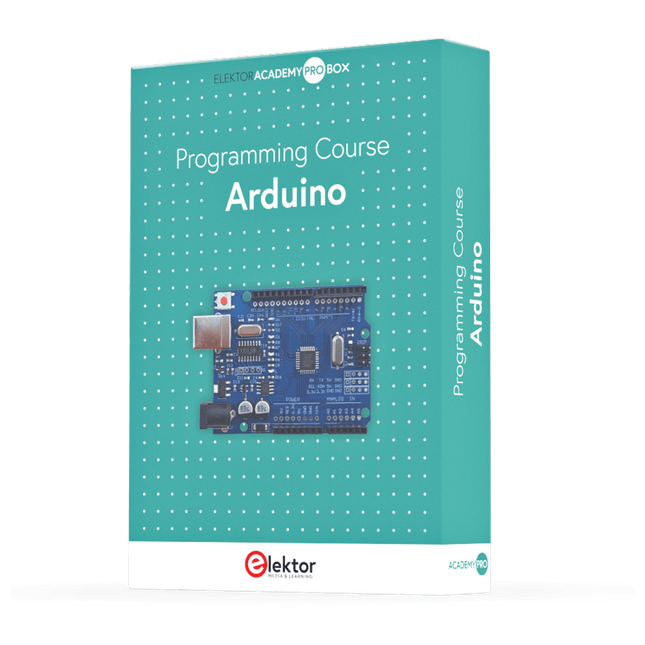
Elektor Academy Pro Arduino (Programming Course)
This complete Arduino Uno-based microcontroller programming course features a textbook, a component kit, hands-on projects, and a comprehensive online course with simulations. It is ideal for step-by-step learning of embedded systems programming with Arduino using a practical, hands-on approach. A Practical Introduction to Embedded Systems with the Arduino Uno This course is designed for people who are new to embedded systems and looking for a structured, example-driven way to get started. A kit of parts comprising LEDs and resistors, switches, sensors and actuators, displays, a breadboard and wires, and more is included. These are used in the course to illustrate example applications. No prior experience with Arduino or embedded development is required. Each section features hands-on examples and mini projects designed to reinforce key concepts and inspire deeper exploration. By the end of the course, you’ll be able not only to reproduce the examples but also to build on them with your own ideas and applications. What Will You Learn? Microcontroller programming with Arduino using the Uno R3 board Working with Digital I/O, read buttons and encoders, control LEDs and relays Read analog inputs, voltages, and analog sensors Generating analog output signals and PWM Use serial communication like UART, I²C and SPI to control displays and read digital sensors and SD cards Managing time Working with interrupts Real-time sensor input and control via buttons, LEDs, and displays Control actuators like relays and servo motors Who Is It For? Students and self-learners exploring embedded systems Makers and IoT enthusiasts looking to improve their hardware skills Educators and trainers seeking ready-to-teach material What's Inside the Box? Access to the full course on the Elektor Academy Pro Learning Platform Uno R3 microcontroller board + USB cable Book: Programming Microcontrollers in C/C++ Using Arduino Downloadable project files for every module Component Box: 2× LED, red, 5 mm LED, green, 5 mm 3× Resistor, 470 Ω, 0.25 W LDR Potentiometer, 10 kΩ, linear Pushbutton Rotary encoder module Relay module DHT22 Humidity & Temperature Sensor TM1637-compatible 4-digit 7-segment display MPU-6050 IMU with headers SSD1306-compatible I²C OLED display Micro SD card adapter with header Buzzer SG90 Micro Servo ILI9341-compatible SPI 240×320 TFT display 20× Jumper wires Breadboard All Programming Courses (and differences in content) Course Arduino Raspberry Pi Pico with Arduino C/C++ ESP32 with Arduino C/C++ Raspberry Pi Pico with MicroPython ESP32 with MicroPython Online Course Access to Arduino Course Access to Pico with Arduino C/C++ Course Access to ESP32 with Arduino C/C++ Course Access to Pico with MicroPython Course Access to ESP32 with MicroPython Course Board Uno R3 Raspberry Pi Pico ESP32 Raspberry Pi Pico ESP32 Book Programming Microcontrollers in C/C++ Using Arduino Programming Microcontrollers in C/C++ Using Arduino Programming Microcontrollers in C/C++ Using Arduino Programming Microcontrollers in MicroPython Programming Microcontrollers in MicroPython Kit 40-piece Component Box 40-piece Component Box 40-piece Component Box 40-piece Component Box 40-piece Component Box
€ 69,95
Members: € 62,96
-
Elektor Digital Microcontroller Basics with PIC (E-book)
In this book the author presents all essential aspects of microcontroller programming, without overloading the reader with unnecessary or quasi-relevant bits of information. Having read the book, you should be able to understand as well as program, 8-bit microcontrollers. The introduction to microcontroller programming is worked out using microcontrollers from the PIC series. Not exactly state-of-the-art with just 8 bits, the PIC micro has the advantage of being easy to comprehend. It is offered in a DIP enclosure, widely available and not overly complex. The entire datasheet of the PIC micro is shorter by decades than the description of the architecture outlining the processor section of an advanced microcontroller. Simplicity has its advantages here. Having mastered the fundamental operation of a microcontroller, you can easily enter into the realms of advanced softcores later. Having placed assembly code as the executive programming language in the foreground in the first part of the book, the author reaches a deeper level with ‘C’ in the second part. Cheerfully alongside the official subject matter, the book presents tips & tricks, interesting measurement technology, practical aspects of microcontroller programming, as well as hands-on options for easier working, debugging and faultfinding.
€ 32,95
Members: € 29,66
-

Elektor Publishing 8-Bit-Mikrocontroller
PIC und AVR verstehen In diesem Buch werden wir uns ausschließlich mit 8-Bit-Mikrocontrollern beschäftigen, und zwar mit Mikrocontrollern der 8-Bit-PIC- und der 8-Bit-AVR-Mikrocontroller-Linien. Bei der PIC-Familie handelt es sich dabei um PIC10, PIC12, PIC16 und PIC18; bei der AVR-Familie um ATtiny, ATmega und ATxmega. Die vorgestellten 8-Bit-Chips sind für sehr viele Anwendungen vollkommen ausreichend und preislich auch attraktiv. Durch die Lektüre des Buches erhalten Sie ein fundiertes Wissen über die genannten 8-Bit-Mikrocontroller, über ihre Architektur, ihre Pinbelegungen und über ihre Programmierung. Weil wir uns in diesem Buch mit den Grundlagen der Architektur der PICs und AVRs vertraut machen möchten, werden wir auch für alle PIC- und AVR-Anwendungen Assembler einsetzen, denn die Assembler-Sprache erlaubt es, die Technik im Detail kennenzulernen. Wenn man wirklich wissen möchte, was sich im Mikrocontroller abspielt, greift man zu Assembler. Damit hat man die beste Gelegenheit, sehr nah an den Kern zu kommen. Und wenn man schon einen Mikrocontroller-Typ kennengelernt und verstanden hat, ist es bei dem nächsten deutlich einfacher, auch wenn er von einem anderen Hersteller kommt. Bei anderen Programmiersprachen bleibt die Technik immer ziemlich tief versteckt. Die Assembler-Beispiele sind so einfach gestaltet, dass sie jeder mit den im Buch aufgezeigten Programmiertechniken erstellen kann. Weil es sich um einfache Beispiele handelt, werden wir sie alle auf einer universellen Lochrasterplatine realisieren. Manche sind auch auf einem Experimentier-Breadboard umsetzbar.
€ 39,80
Best Price
-

Red Pitaya Red Pitaya STEMlab 125-14 PRO Gen 2 Starter Kit (incl. Book)
This bundle includes the Red Pitaya STEMlab 125-14 PRO Gen 2 Starter Kit and the new book "Experimenting with Red Pitaya STEMlab Gen 2". The Red Pitaya STEMlab 125-14 PRO Gen 2 Starter Kit is a powerful and flexible platform for signal processing, data acquisition, and electronic measurement applications. Designed for engineers, developers, researchers, and educators, this kit provides everything required to start building advanced measurement and control systems. At the core of the kit is the STEMlab 125-14 PRO Gen 2 board, an upgraded and ultra-lightweight development platform. Powered by the Xilinx Zynq-7010 SoC with 512 MB of RAM, it combines FPGA programmability with ARM processing power to enable high-performance instrumentation and custom signal-processing solutions. The board offers 14-bit ADC and DAC resolution, a 125 MS/s sampling rate, an input range of ±20 V, and up to 60 MHz bandwidth. Its improved low-noise analog front-end, USB-C connectivity, and compact design make it suitable for demanding applications such as RF development, radar systems, photonics research, software-defined radio (SDR), and industrial automation. The Starter Kit includes all essential accessories for immediate use: a microSD card with preinstalled operating system, power supply, Ethernet cable for remote access, two 100 MHz oscilloscope probes, and SMA-to-BNC adapters for flexible signal connections. The Red Pitaya STEMlab 125-14 PRO Gen 2 Starter Kit is an excellent platform for rapid prototyping, FPGA development, measurement instrumentation, and advanced electronics experimentation. Features 14-bit ADC and DAC resolution 125 MS/s sampling rate ±20 V input range Up to 60 MHz bandwidth Xilinx Zynq-7010 SoC (FPGA + ARM processor) 512 MB RAM Low-noise analog front- and back-ends Applications RF development and testing Radar and wireless systems Software-defined radio (SDR) Photonics and optical research Industrial automation and control systems Signal analysis and instrumentation Rapid prototyping of electronic measurement systems Specifications Processor Dual-core ARM Cortex-A9 FPGA AMD Xilinx Zynq-7010 SoC RAM 512 MB (4 Gb) Storage microSD card (up to 32 GB) Operating System Linux-based Red Pitaya OS ADC Resolution 14-bit DAC Resolution 14-bit Bandwidth 60 MHz (DC) Sampling Rate 125 MS/s Analog Input Channels 2 Analog Output Channels 2 Input Voltage Range ±1 V (LV) / ±20 V (HV) Input Impedance 1 MΩ / 10 pF Output Voltage Range ±1 V Ethernet 1x Gigabit Ethernet (RJ45) USB 2x USB-C 2.0 (for power and console) Digital I/O 16x GPIO (3.3 V) Communication Interfaces I²C, SPI, UART, CAN Power Supply 5 V/3 A via USB-C Dimensions 106.8 x 60.0 x 17.9 mm Included 1x Red Pitaya STEMlab 125-14 PRO Gen 2 board 2x 100 MHz oscilloscope probes 2x SMA-to-BNC adapters 1x microSD card with preinstalled OS 1x USB-C Power supply 1x Ethernet cable Downloads Documentation Schematics Book: Experimenting with Red Pitaya STEMlab Gen 2 With this new book, Red Pitaya goes beyond a versatile board. It becomes a powerful laboratory instrument for precision measurement, analysis, and control. From the fundamentals of electronic project development, monitoring, control, and design to testing, this book walks you step-by-step through everything you need to know to harness the full potential of Red Pitaya hardware and software. The book presents real-time, FPGA-based projects that are developed on a PC using the Vivado environment, then transferred to the Red Pitaya for execution and testing. You will learn about enhanced performance, expanded I/O capabilities, improved FPGA features, and advanced connectivity options that open up new frontiers for precision measurement, monitoring, and control in your embedded applications. Inside the book you will discover: A deep dive into Red Pitaya architecture and hardware design Electronic experiments using Red Pitaya for measurement and monitoring Hands-on projects using the Python programming language Practical guidance for FPGA programming using Red Pitaya Red Pitaya FPGA projects using the Verilog HDL under Vivado IDE Practical design of electronic projects including measurement and testing Step-by-step examples that bridge theory and real-world implementation Whether you are designing your own electronic circuits, developing signal analysis tools, or creating real-time control or monitoring systems, this book provides you the knowledge and confidence you need to fully learn and customize the Red Pitaya platform.
€ 799,00
Best Price
-

SunFounder Universal Maker Sensor Kit (for Raspberry Pi, Pico W, Arduino, ESP32)
Discover endless creativity with the Universal Maker Sensor Kit, designed for use with Raspberry Pi, Pico W, Arduino, and ESP32. This versatile kit offers compatibility across popular development platforms, including Arduino Uno R4 Minima/WiFi, Uno R3, Mega 2560, Raspberry Pi 5, 4, 3B+, 3B, Zero, Pico W, and ESP32. Featuring over 35 sensors, actuators, and displays, it's perfect for projects ranging from environmental monitoring and smart home automation to robotics and interactive gaming. Step-by-step tutorials in C/C++, Python, and MicroPython guide beginners and experienced makers alike through 169 exciting projects. Features Wide Compatibility: Fully supports Arduino (Uno R3, Uno R4 Minima/WiFi, Mega 2560), Raspberry Pi (5, 4, 3B+, 3B, Zero, Pico W), and ESP32, enabling extensive flexibility across numerous development platforms. Includes instructions for building 169 projects. Comprehensive Components: Features more than 35 sensors, actuators, and display modules suitable for diverse projects such as environmental monitoring, smart home automation, robotics, and interactive game controllers. Detailed Tutorials: Provides clear, step-by-step tutorials covering Arduino, Raspberry Pi, Pico W, ESP32, and each included component. Tutorials are available in C/C++, Python, and MicroPython, catering effectively to both beginners and experienced makers. Suitable for All Skill Levels: Offers structured projects designed to guide users seamlessly from beginner to advanced proficiency in electronics and programming, enhancing creativity and technical expertise. Included Breadboard Button Module Capacitive Soil Moisture Module Flame Sensor Module Gas/Smoke Sensor Module (MQ2) Gyroscope & Accelerometer Module (MPU6050) Hall Sensor Module Infrared Speed Sensor Module IR Obstacle Avoidance Sensor Module Joystick Module PCF8591 ADC DAC Converter Module Photoresistor Module PIR Motion Module (HC-SR501) Potentiometer Module Pulse Oximeter and Heart Rate Sensor Module (MAX30102) Raindrop Detection Module Real Time Clock Module (DS1302) Rotary Encoder Module Temperature Sensor Module (DS18B20) Temperature and Humidity Sensor Module (DHT11) Temperature, Humidity & Pressure Sensor (BMP280) Time of Flight Micro-LIDAR Distance Sensor (VL53L0X) Touch Sensor Module Ultrasonic Sensor Module (HC-SR04) Vibration Sensor Module (SW-420) Water Level Sensor Module I²C LCD 1602 OLED Display Module (SSD1306) RGB LED Module Traffic Light Module 5 V Relay Module Centrifugal Pump L9110 Motor Driver Module Passive Buzzer Module Servo Motor (SG90) TT Motor ESP8266 Module JDY-31 Bluetooth Module Power Supply Module Documentation Online Tutorial
€ 69,95
Members: € 62,96
-

Sensepeek Sensepeek 6012 PCBite Kit incl. 2x SQ10 Probe for DMM
The SQ series of handsfree PCBite probes from Sensepeek are insulated, come with included color-coded cable holders and have a lower point of gravity making them even more stable compared with the original SP series of probes. All the loved features of handsfree measurement, exchangeable fine pitch spring tipped test needle and the minimalistic design is maintained to make traditional sized and handheld probes obsolete. Features All handsfree probes from Sensepeek makes instant measurements or long triggering sessions a breeze. No more soldering wires to connect your probe or complicated tools to setup, just positioning the probe needle on any test point or component in the signal path and release. Saves time and frustration during development, verification and repairs. The minimalist design and the spring-loaded test needle makes it possible to simultaneously measure on fine pitch components and nearby signals. Both length and weight of the SQ probes are perfectly balanced to be used with PCBite PCB holders and base plate which is a must for handsfree function. The probe holder comes with a powerful magnet in the base, as for all PCBite probes and holders which makes the probe easy to place and reposition. The SQ series of probes can be used handheld without the probe holder as they have an insulated grip but their full potential is used when measuring handsfree. Included 4x PCBite PCB holders 2x SQ10 probes and pin tipped test needles (red/black) 2x Banana to dupont test wires (red/black) 1x Large Base plate (A4) 1x Insulation cover for the base plate (A4) 1x Set of yellow insulation washers for the PCB holders 1x Set of cable holders (red/black) 2x Extra test needles 1x Micro fiber cloth Downloads User Guide (PCBite Kit) User Guide (SQ10)
€ 127,05
-
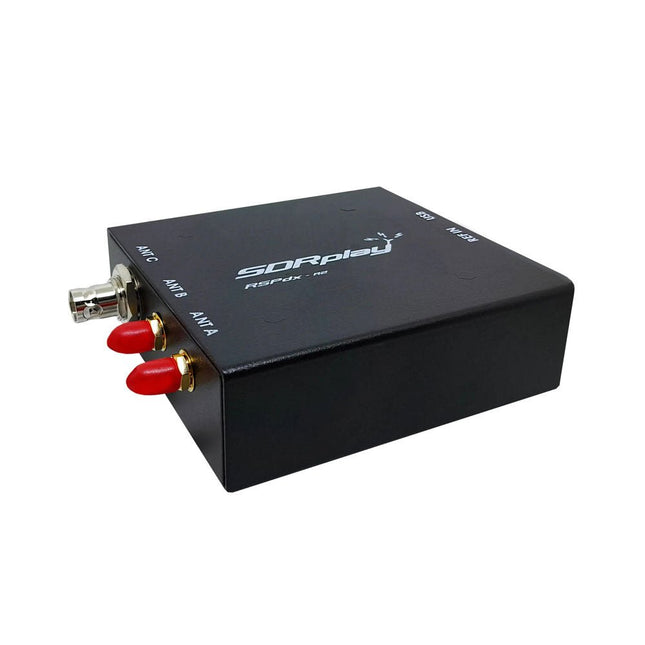
SDRplay SDRplay RSPdx-R2 Single-Tuner 14-bit SDR Receiver (1 kHz to 2 GHz)
The SDRplay RSPdx-R2 is a wideband full featured single-tuner 14-bit SDR receiver which covers the entire RF spectrum from 1 kHz to 2 GHz giving up to 10 MHz of spectrum visibility. It contains three antenna ports, two of which use SMA connectors and operate across the full 1 kHz to 2 GHz range and the third uses a BNC connector which operates up to 200 MHz. The RSPdx-R2 is an enhanced version of the RSPdx with further design improvements for use at frequencies below 2 MHz. Housed in a strong steel case, in addition to the functionality of the RSP1B, the RSPdx-R2 provides three software selectable antenna inputs and an external clock input. It offers excellent performance through HF and VHF frequencies all the way up to 2 GHz. The RSPdx-R2 also supports an "HDR mode" optimised for the demanding radio reception conditions below 2 MHz. The RSPdx-R2, when used in conjunction with SDRplay’s own software, introduces a special HDR (High Dynamic Range) mode for reception within selected bands below 2 MHz. HDR mode delivers improved intermodulation performance and fewer spurious responses for those challenging bands. Features Covers all frequencies from 1 kHz through VLF, LF, MW, HF, VHF, UHF and L-band to 2 GHz, with no gaps Receive, monitor and record up to 10 MHz of spectrum at a time Significantly improved noise performance below 1 MHz (i.e. for some MF, LF and below) Improved dynamic range below 2 MHz both in tuner mode and HDR mode HDR mode below 2 MHz giving overall dynamic range and selectivity advantages Software selectable choice of 3 antenna ports External clock input for synchronisation purposes, or connection to GPS reference clock for extra frequency accuracy Excellent dynamic range for challenging reception conditions Free use of Windows-based SDRuno software (check website for versions supported) Free use of SDRconnect SDR and server software for Windows, MacOS and Linux (Check website for versions supported) Multiplatform driver and API support including Windows, Linux, Mac and Raspberry Pi 4/5 Strong and growing software support network Calibrated S meter/RF power and SNR measurement with SDRuno (including datalogging to .CSV file capability) Documented API provided to allow demodulator or application development on multiple platforms Applications (Amateur) Shortwave radio listening Broadcast DXing (AM/FM/TV) Panadaptor Aircraft (ADS-B and ATC) Slow Scan TV Multi-amateur band monitoring WSPR & digital modes Weather fax (HF and satellite) Satellite monitoring Geostationary environmental satellites Trunked radio Utility and emergency service monitoring Fast and effective antenna comparison Applications (Industrial) Spectrum Analyser Surveillance Wireless microphone monitoring RF surveying IoT receiver chain Signal logging RFI/EMC detection Broadcast integrity monitoring Spectrum monitoring Power measurement Applications (Educational/Scientific) Teaching Receiver design Radio astronomy Passive radar Ionosonde Spectrum analyser Receiver for IoT sensor projects Antenna research Specifications Frequency Range 1 kHz – 2 GHz Antenna Connector SMA Antenna Impedance 50 Ohms Current Consumption (Typical) 190 mA @ >60 MHz (excl. Bias-T)120 mA @ <60 MHz (excl. Bias-T) USB Connector USB-B Maximum Input Power +0 dBm Continuous+10 dBm Short Duration ADC Sample Rates 2-10.66 MSPS ADC Number of Bits 14 bit 2-6.048 MSPS12 bit 6.048-8.064 MSPS10 bit 8.064-9.216 MSPS8 bit >9.216 MSPS Bias-T 4.7 V100 mA guaranteed Reference 0.5ppm 24 MHz TCXOFrequency error trimmable to 0.01ppm in field Operating Temperature −10˚C to +60˚C Dimensions 113 x 94 x 35 mm Weight 315 g Downloads Datasheet Software RSPdx-R2 vs RSPduo RSPdx-R2 RSPduo Continuous coverage from 1 kHz to 2 GHz ✓ ✓ Up to 10 MHz visible bandwidth ✓ ✓ 14-bit ADC silicon technology plus multiple high-performance input filters ✓ ✓ Software selectable AM/FM & DAB broadcast band notch filters ✓ ✓ 4.7 V Bias-T for powering external remote antenna amplifier ✓ ✓ Powers over the USB cable with a simple type B socket ✓ ✓ 50Ω SMA antenna input(s) for 1 kHz to 2 GHz operation (software selectable) 2 2 Additional software selectable Hi-Z input for up to 30 Mhz operation ✓ Additional software selectable 50Ω BNC input for up to 200 MHz operation ✓ Additional LF/VLF filter for below 500 kHz ✓ 24 MHz reference clock input (+ output on RSPduo) ✓ ✓ Dual tuners enabling reception on 2 totally independent 2 MHz ranges ✓ Dual tuners enabling diversity reception using SDRuno ✓ Rugged black painted steel case ✓ ✓ Overall performance below 2 MHz for MW and LF ++ + Multiple simultaneous applications + ++ Performance in challenging fading conditions (*using diversity tuning) + *++
€ 263,00
-

Elektor November/December 2026 (EN)
Elektor GREEN and GOLD members can download their digital edition here. Not a member yet? Click here. AI Tools for Hardware PrototypingWhat Helps, What Does Not, and Where the Engineer Still Has to Sit ZSWatch — From Idea to ProductPart 1: A Completely Open Smartwatch Three-Way Tone ControlHigh-End — For That Little Bit Extra electronica Fast Forward 202610 Years of Innovation Microcontroller PrototypingAn Overview of Popular Boards Prototyping BreadboardsPeculiar Parts, the Series Designing for OrbitA Maker’s Guide to COTS Selection, Radiation Resilience, and Mission Architecture Thermal Management for Reliable ElectronicsWhen Every Degree Counts From Concept to GadgetBuilding Embedded Systems That Ship Understanding the EU Cyber Resilience ActWhat the CRA Demands and How to Meet It: A Guide for Embedded Engineers Lusight: Printed Displays You Can Reveal with Your PhoneDiscover What Is Inside the Badge on the Cover of Elektor’s electronica Edition Teaching a Robot Arm to See and MoveAI-Driven Manipulation Using a 3D-Printed Robot Loop Antenna with RF BricksPart 2: Signal Processing From Prototype to ProductionPractical Lessons from the Elektor Community Project UpdatesFeedback, Ideas, Corrections Handheld Audio GeneratorA Reference Signal Source for Quick Audio Systems Setup AudiotronicsMore Distortion, and a Level-Matching Amplifier 2026: An AI OdysseyWhen AI Starts Building AI Wireless Workshop (2)Radio Modules Unlocked: 2.4-GHz nRF24L01P Transceiver The Digital Path Building an Open-Source SmartwatchDaniel Kampert on ZSWatch, Open Hardware, and Engineering Trade-Offs How to Prepare for Professional SMD Assembly Engineering Beyond the BenchSystem Integration, Troubleshooting, and Real-World Testing Elektor at 65Projects from Novembers and Decembers Past Avionics Instrument SimulatorESP32-S3-Based, with Round HMI Display
€ 14,90
-

Elektor Digital 8-Bit-Mikrocontroller (PDF)
PIC und AVR verstehen In diesem Buch werden wir uns ausschließlich mit 8-Bit-Mikrocontrollern beschäftigen, und zwar mit Mikrocontrollern der 8-Bit-PIC- und der 8-Bit-AVR-Mikrocontroller-Linien. Bei der PIC-Familie handelt es sich dabei um PIC10, PIC12, PIC16 und PIC18; bei der AVR-Familie um ATtiny, ATmega und ATxmega. Die vorgestellten 8-Bit-Chips sind für sehr viele Anwendungen vollkommen ausreichend und preislich auch attraktiv. Durch die Lektüre des Buches erhalten Sie ein fundiertes Wissen über die genannten 8-Bit-Mikrocontroller, über ihre Architektur, ihre Pinbelegungen und über ihre Programmierung. Weil wir uns in diesem Buch mit den Grundlagen der Architektur der PICs und AVRs vertraut machen möchten, werden wir auch für alle PIC- und AVR-Anwendungen Assembler einsetzen, denn die Assembler-Sprache erlaubt es, die Technik im Detail kennenzulernen. Wenn man wirklich wissen möchte, was sich im Mikrocontroller abspielt, greift man zu Assembler. Damit hat man die beste Gelegenheit, sehr nah an den Kern zu kommen. Und wenn man schon einen Mikrocontroller-Typ kennengelernt und verstanden hat, ist es bei dem nächsten deutlich einfacher, auch wenn er von einem anderen Hersteller kommt. Bei anderen Programmiersprachen bleibt die Technik immer ziemlich tief versteckt. Die Assembler-Beispiele sind so einfach gestaltet, dass sie jeder mit den im Buch aufgezeigten Programmiertechniken erstellen kann. Weil es sich um einfache Beispiele handelt, werden wir sie alle auf einer universellen Lochrasterplatine realisieren. Manche sind auch auf einem Experimentier-Breadboard umsetzbar.
€ 32,80
Members: € 29,52
-

Elektor Digital Explore ATtiny Microcontrollers using C and Assembly Language (E-book)
AVR Architecture and Programming An in-depth look at the 8-bit AVR architecture found in ATtiny and ATmega microcontrollers, mainly from a software and programming point of view. Explore the AVR architecture using C and assembly language in Microchip Studio (formerly Atmel Studio) with ATtiny microcontrollers. Learn the details of how AVR microcontrollers work internally, including the internal registers and memory map of ATtiny devices. Program ATtiny microcontrollers using an Atmel-ICE programmer/debugger, or use a cheap hobby programmer, or even an Arduino Uno as a programmer. Most code examples can be run using the Microchip Studio AVR simulator. Learn to write programs for ATtiny microcontrollers in assembly language. See how assembly language is converted to machine code instructions by the assembler program. Find out how programs written in the C programming language end up as assembly language and finally as machine code instructions. Use the Microchip Studio debugger in combination with a hardware USB programmer/debugger to test assembly and C language programs, or use the Microchip Studio AVR simulator. DIP packaged ATtiny microcontrollers are used in this volume for easy use on electronic breadboards, targeting mainly the ATtiny13(A) and ATtiny25/45/85. Learn about instruction timing and clocks in AVR microcontrollers using ATtiny devices. Be on your way to becoming an AVR expert with advanced debugging and programming skills.
€ 34,95
Members: € 31,46
-
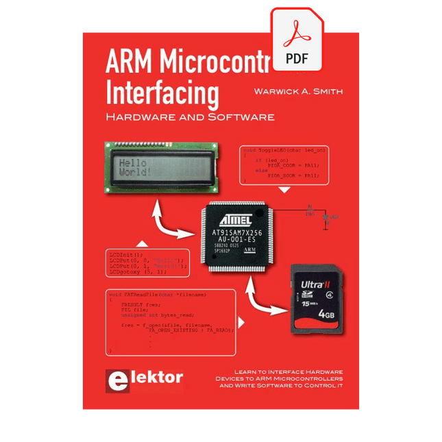
Elektor Digital ARM Microcontroller Interfacing (E-book)
Learn to interface and program hardware devices in a wide range of useful applications, using ARM7 microcontrollers and the C programming language. Examples covered in full detail include a simple LED to a multi-megabyte SD card running the FAT file system. Features of this book Build prototype circuits on breadboard or Veroboard and interface to ARM microcontrollers. A 32-bit ARM7 microcontroller is used in interfacing and software examples. Interfacing principles apply to other ARM microcontrollers and other non-ARM microcontrollers as well. Example programs are written in the C programming language. Use only free or open source software. Download and install all programming tools from the Internet. Template project files are provided for easy project creation. Hardware Interface to LEDs, transistors, optocouplers, relays, solenoids, switches, keypads, LCD displays, seven segment displays, DC motors, stepper motors, external analogue signals using the ADC, RS232, RS-485, TWI, USB, SPI and SD memory cards. Software Once hardware has been interfaced to a microcontroller, software must be written to control the hardware. You will learn how to write programs to operate externally interfaced hardware devices, use timers and interrupts. Also learn how to port FAT file system code for use with an SD memory card, program the PWM to produce an audio sine wave, program the PWM to speed control a DC motor and more. A chapter on more advanced ARM microcontrollers is included with an overview of some of the newest ARM microcontrollers and their features.
€ 29,95
Members: € 26,96
-
Elektor Digital Microprocessor Design Using Verilog HDL (E-book)
If you have the right tools, designing a microprocessor shouldn’t be complicated. The Verilog hardware description language (HDL) is one such tool. It can enable you to depict, simulate, and synthesize an electronic design, and thus increase your productivity by reducing the overall workload associated with a given project.Monte Dalrymple’s Microprocessor Design Using Verilog HDL is a practical guide to processor design in the real world. It presents the Verilog HDL in a straightforward fashion and serves as a detailed introduction to reducing the computer architecture and as an instruction set to practice. You’re led through the microprocessor design process from start to finish, and essential topics ranging from writing in Verilog to debugging and testing are laid bare.The book details the following, and more: Verilog HDL Review: data types, bit widths/labeling, operations, statements, and design hierarchy Verilog Coding Style: files vs. modules, indentation, and design organization Design Work: instruction set architecture, external bus interface, and machine cycle Microarchitecture: design spreadsheet and essential worksheets (e.g., Operation, Instruction Code, and Next State) Writing in Verilog: choosing encoding, assigning states in a state machine, and files (e.g., defines.v, hierarchy.v, machine.v) Debugging, Verification, and Testing: debugging requirements, verification requirements, testing requirements, and the test bench Post Simulation: enhancements and reduction to practice Monte Dalrymple received a BSEE (with highest honors) and an MSEE from the University of California at Berkeley, where he was elected to Phi Beta Kappa. Monte started his career at Zilog, where he designed a number of successful products, including the Serial Communication Controller (SCC) family and the Universal Serial Controller (USC) family. He was also the architect and lead designer of the Z380 microprocessor. Monte started his own company, Systemyde International Corp., in 1995, and has been doing contract design work ever since. He designed all five generations of Rabbit microprocessors, a Z180 clone that is flying on the Juno mission to Jupiter, and a Z8000 clone that flies in a commercial avionics air data computer. Monte holds 16 patents as well as both amateur and commercial radio licenses. Monte wrote 10 articles for Circuit Cellar magazine between 1996 and 2010. He recently completed a side project to replace the CPU in an HP-41C calculator with a modern FPGA-based version.
€ 29,95
Members: € 26,96


