This desk lamp is ideal for your workplace. With the 5-inch 5D-lens, the finest work can be done. The lamp has 80 integrated LEDs.
Features
Lens size: 5 inch
Lens material: glass
Diopter: 5D
Light source: T5 22 W fluorescent energy-saving bulb (80pcs LED)
Voltage: 220-240 V
Power: 22 W
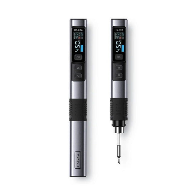
The FNIRSI HS-02A is an improved version of the HS-01 soldering iron with a better grip and a shorter tip for more comfort and precision during use. It features a larger 0.96-inch IPS HD color display that allows for better visibility of settings and status. With an output power of 100 W, the HS-02A heats up quickly and reaches operating temperature in about 2 seconds. The temperature is adjustable in a range of 100-450°C (212-842°F) to meet different soldering requirements.
Features
Temperature: 100-450°C (212-842°F)
Accurate temperature adjusting and control
Fast heating
CNC Metal Shell
Adaptive Power
100 W High Power
Protocols: PD, QC
Specifications
Temperature Range
100-450°C (212-842°F)
Working Voltage
9-20 V
Display
0.96" IPS HD Color Screen
Power Supply
USB-C
Fast Charging Protocols
PD / QC
Power
100 W (max)
Dimensions
180 x 20 mm
Weight
61 g
Included
1x FNRISI HS-02A Smart soldering iron
6x Soldering iron tips (HS02A-KU, HS02A-K, HS02A-JS, HS02A-I, HS02A-C2, HS02A-B)
1x Mini soldering iron stand
1x Manual
Downloads
Manual
Firmware V1.7
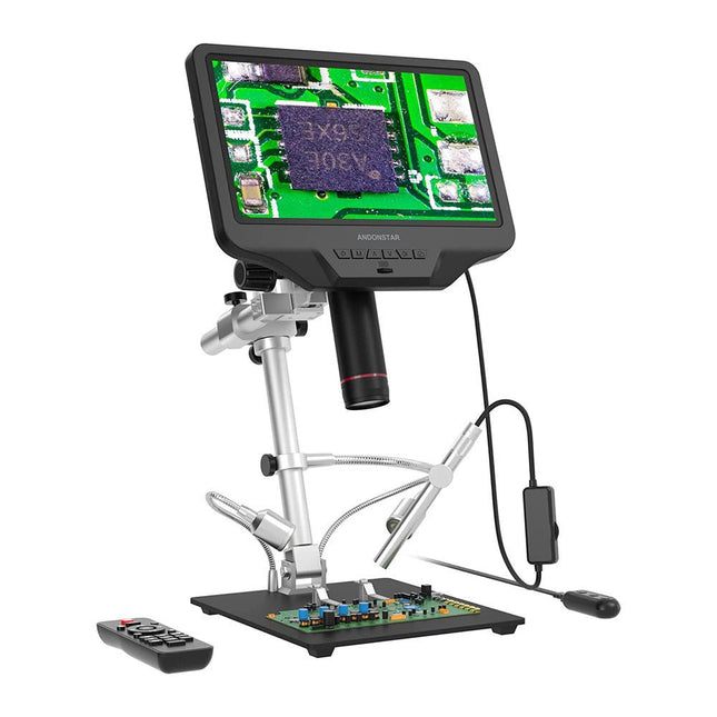
The Andonstar AD409 Pro-ES is a digital microscope with an extra-high stand that is also equipped with an endoscope. The microscope allows clear observation of the sides of components, the inside of pipes, etc., enabling 360° observation without dead angles. The microscope also has a remote control that allows you to easily switch between the following image modes: two-lens, microscope and endoscope.
Features
High-quality metal lens and focusing barrel
Professional HDMI digital microscope supports multiple output methods
Soldering Microscope with Pro Metal Stand
Unique UV filter design
8 Levels adjustable LED Lights
Convenient Wireless Remote Control
Professional Measurement Software
Specifications
Screen size
10.1 inch (25.7 cm)
Image sensor
4 MP
Video output
UHD 2880x2160 (24fps)FHD 1920x1080 (60fps/30fps)HD 1280x720 (120fps)
Video format
MP4
Magnification
Up to 300 times (27 inch HDMI monitor)
Photo resolution
Max. 12 MP (4032x3024)
Photo format
JPG
Focus range
Min. 5 cm
Frame Rate
Max. 120fps
Video interface
HDMI
Storage
microSD card (up to 64 GB)
PC support
Windows, PC software with measurement
Mobile phone, tablet terminal support
Support WiFi connection and measurement
Power source
5 V DC
Light source
2 LEDs with the stand
Endoscope
Yes
Stand size
18 x 20 x 32 cm
Included
1x Andonstar AD409 Pro-ES Digital Microscope
1x Endoscope
1x Metal stand with 2 LEDs
1x UV filter (already assembled in the lens)
1x IR remote
1x Switch cable
1x Power adapter
1x Wrench
2x Metal clips
1x HDMI cable
1x User manual
Downloads
Manual
Software
L'électronique est passionnée. C'est un plaisir amusant et instructif. Elle permet d'acquérir de nouvelles compétences, souvent utiles, à la maison et même au travail. Une expérience électronique avec ces circuits appropriés. Il donne vie à ses projets. Avant que le jour n'arrive, vous avez hâte de le voir ! Il est nécessaire de rassembler les articles pour la publication des articles du magazine d'électronique Elektor. Il sera le compagnon de vos progrès dans le monde de l'électronique.
Plus que commencer par l'électronique analogique. Vous pourrez découvrir les compositions et les circuits ainsi que les simples pour comprendre les fonctions, les interactions et les problèmes éventuels. La meilleure façon de progresser, c'est de faire des expériences réelles, car la théorie ne suffit pas. Un guide en direct pour un excellent guide de montages pratiques, notamment pour les débutants. Et pour en savoir plus, acquérir la meilleure expérience et connaissance.
La deuxième partie de la vie du monde du numérique électronique. En savoir plus sur l’utilisation des microcontrôles. Les effets des composants sont discrets grâce aux circuits intégrés des principaux composants des microcontrôleurs. La programmation à long terme de BASCOM, basée sur les pré-requis à la mise en œuvre d'Arduino, BBC micro:bit et d'autres, facilite la prise en compte de l'apprentissage. Voici une description détaillée des nombreuses applications des microcontrôleurs, abordables pour les néophytes. Ici, programmation et soudage font bon ménage !
Mit dem Elektor Arduino Nano Trainingsboard (MCCAB) eigene Projekte realisieren
Der Mikrocontroller ist das wohl faszinierendste Teilgebiet der Elektronik, denn aufgrund der Vielzahl von Funktionen, die er auf seinem Chip vereinigt, ist er für den Entwickler ein universelles Multi-Tool zur Realisierung seiner Projekte. Praktisch jedes Gerät des täglichen Gebrauchs wird heute von einem Mikrocontroller gesteuert. Für einen elektronischen Laien blieb es aufgrund der Komplexität bisher allerdings ein Wunschtraum, eigene Ideen mit einem Mikrocontroller zu realisieren. Das Arduino-Konzept hat den Einsatz von Mikrocontrollern weitgehend vereinfacht, sodass jetzt auch Laien eigene Elektronik-Ideen mit einem Mikrocontroller verwirklichen können.
Buch & Hardware im Bundle: 'Learning by Doing'
Dieses im Bundle mitgelieferte Buch (im großen A4-Format) zeigt, wie man auch ohne große Erfahrung in Elektronik und Programmiersprachen eigene Projekte mit einem Mikrocontroller realisieren kann. Es ist ein Mikrocontroller-Praxiskurs für Einsteiger, denn nach einem Überblick über die Interna des Mikrocontrollers und einer Einführung in die Programmiersprache C liegt der Schwerpunkt des Kurses auf den praktischen Übungen. Der Leser eignet sich die erforderlichen Kenntnisse durch 'Learning by Doing' an: in dem umfangreichen Praxisteil mit 12 Projekten und 46 Übungen wird das im vorderen Teil des Buches Gelernte mit vielen Beispielen unterlegt. Die Übungen sind dabei so aufgebaut, dass der Bearbeiter eine Aufgabenstellung erhält, die er mit seinem im Theorieteil des Buches aufgebauten Wissen löst. Für jede Übung gibt es anschließend eine ausführlich erklärte und kommentierte Musterlösung, die dem Bearbeiter bei Problemen weiterhilft und die er mit seiner eigenen Lösung vergleichen kann.
Arduino IDE
In der Arduino IDE, einer Software-Entwicklungsumgebung, die kostenlos auf den eigenen PC heruntergeladen werden kann und die das gesamte Softwarepaket enthält, das für ein eigenes Mikrocontroller-Projekt benötigt wird, schreibt der Bearbeiter mit dem Editor der IDE seine Programme („Apps“) in der Programmiersprache C. Der in die Arduino IDE integrierte Compiler übersetzt sie in die Bits und Bytes, die der Mikrocontroller versteht und die dann über ein USB-Kabel in den Speicher des Mikrocontrollers auf dem Elektor Arduino Nano Trainingsboard (MCCAB) geladen werden.
Externe Sensoren, Motoren oder Baugruppen abfragen oder steuern
Das Elektor Arduino Nano Trainingsboard (MCCAB) enthält neben einem Mikrocontrollermodul Arduino Nano alle für die Übungen benötigten Bauteile wie Leuchtdioden, Schalter, Taster, akustische Signalgeber usw. Auch externe Sensoren, Motoren oder Baugruppen können mit diesem Mikrocontroller-Übungssystem abgefragt oder gesteuert werden.
Technische Daten (Arduino Nano Trainingsboard MCCAB)
Stromversorgung
Über die USB-Verbindung des zur Erstellung der Programme sowieso angeschlossenen PCs oder ein externes Netzteil (nicht im Lieferumfang enthalten)
Betriebsspannung
+5 Vcc
Eingangsspannung
Alle Eingänge
0 V bis +5 V
VX1 und VX2
+8 V bis +12 V (nur bei Verwendung eines externen Netzteils)
Mikrocontrollermodul
Arduino Nano
Hardwareperipherie
LCD
2x16 Zeichen
Potenziometer P1 & P2
JP3: Auswahl der Betriebsspannung von P1 & P2
Verteiler
SV4: Verteiler für die BetriebsspannungenSV5, SV6: Verteiler für die Ein-/Ausgänge des Mikrocontrollers
Schalter und Taster
RESET-Taster auf dem Arduino Nano-Modul6x Tastschalter K1 … K66x Schiebeschalter S1 … S6JP2: Verbindung der Schalter mit den Eingängen des Mikrocontrollers
Summer
Piezo-Summer Buzzer1 mit Steckbrücke auf JP6
Leuchtanzeigen
LED L auf dem Arduino Nano-Modul, verbunden mit GPIO D1311x LED: Zustandsanzeige für die Ein-/AusgängeJP6: Verbindung der LEDs LD10 … LD20 mit den GPIOs D2 … D12
Serielle SchnittstellenSPI & I²C
JP4: Auswahl des Signals an Pin X der SPI-Steckerleiste SV12SV9 bis SV12: SPI-Interface (3,3 V/5 V) bzw. I²C-Interface
Schaltausgang für externe Geräte
SV1, SV7: Schaltausgang (maximal +24 V/160 mA, extern zugeführt)SV2: 2x13 Pins zum Anschluss externer Module
3x3 LED-Matrix (9 rote LEDs)
SV3: Spalten der 3x3 LED-Matrix (Ausgänge D6 … D8)JP1: Verbindung der Reihen mit den GPIOs D3 … D5
Software
Library MCCABLib
Steuerung der Hardware-Komponenten (Schalter, Taster, Leuchtdioden, 3x3 LED-Matrix, Summer) auf dem MCCAB Trainingsboard
Betriebstemperatur
bis +40 °C
Abmessungen
100 x 100 x 20 mm
Technische Daten (Arduino Nano)
Mikrocontroller
ATmega328P
Architektur
AVR
Betriebsspannung
5 V
Flashspeicher
32 KB, davon 2 KB vom Bootloader belegt
SRAM
2 KB
Taktfrequenz
16 MHz
Analoge IN-Pins
8
EEPROM
1 KB
DC-Strom pro I/O-Pin
40 mA an einem I/O-Pin, insgesamt maximal 200 mA an allen Pins gemeinsam
Eingangsspannung
7-12 V
Digitale I/O-Pins
22 (6 davon sind PWM-fähig)
PWM-Ausgänge
6
Stromverbrauch
19 mA
Abmessungen
18 x 45 mm
Gewicht
7 g
Lieferumfang
Elektor Arduino Nano MCCAB Trainingsboard
Arduino Nano
Buch: Mikrocontroller-Praxiskurs für Arduino-Einsteiger
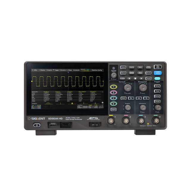
The Siglent SDS814X HD digital storage oscilloscope is based on 2 GSa/s, 12-bit Analog-Digital Converters and front ends with excellent noise floor performance. With a 100 MHz bandwidth, and a maximum record length of 50 Mpts, and the capability to analyze 4 analog channels alongside 16 digital channels, the SDS814X HD is perfectly suited for mixed signal analysis.
Features
12-bit High Resolution
12-bit Analog-Digital Convertors with sample rate up to 2 GSa/s
Front ends with 70 μVrms noise floor @ 100 MHz bandwidth
2/4 analog channels, up to 700 MHz bandwidth
SPO technology
Waveform capture rate up to 80,000 wfm/s (normal mode), and 500,000 wfm/s (sequence mode)
Supports 256-level intensity grading and color temperature display modes.
Up to 50 Mpts record length
Digital trigger system
Intelligent trigger: Edge, Slope, Pulse width, Window, Runt, Interval, Dropout, Pattern, Video (HDTV supported), Qualified, Nth edge, Delay, Setup/Hold time.
Serial bus triggering and decoder, supports protocols I²C, SPI, UART, CAN, LIN.
Segmented acquisition (Sequence) mode, dividing the maximum record length into multiple segments (up to 80,000), according to trigger conditions set by the user, with a very small dead time between segments to capture the qualifying event.
History waveform record (History) function, the maximum recorded waveform length is 80,000 frames.
Automatic measurements on 50+ parameters, supports statistics with histogram, track, trend, Gating measurement, and measurements on Math, History and Ref.
4 Math traces (2 Mpts FFT, addition, subtraction, multiplication, division, integration, differential, square root, etc.), supports formula editor.
Abundant data analysis functions such as Search, Navigate, Counter, Bode plot and Power Analysis
High Speed hardware-based Mask Test function, with Mask Editor tool for creating user-defined masks
16 digital channels (optional)
25 MHz waveform generator (optional)
7" TFT-LCD display with 1024 x 600 resolution; Capacitive touch screen supports multi-touch gestures.
Interfaces include: USB Hosts, USB Device (USBTMC), LAN (VXI-11/Telnet/Socket), Pass/Fail, Trigger Out
Built-in web server supports remote control over the LAN port using a web browser. Supports SCPI remote control commands. Supports external mouse and keyboard. Supports NTP.
Specifications
Analog Channels
4
Bandwidth
100 MHz
Vertical resolution
12-bit
Sample rate (Max.)
One channel mode: 2 GSa/sTwo channel mode: 1 GSa/sFour channel mode: 500 MSa/s
Memory depth (Max.)
One channel mode: 50 Mpts/chTwo channel mode: 25 Mpts/chFour channel mode: 10Mpts/ch
Waveform capture rate (Max.)
Normal mode: 80,000 wfm/sSequence mode: 500,000 wfm/s
Trigger type
Edge, Slope, Pulse width, Window, Runt, Interval, Dropout, Pattern, Video, Qualified, Nth edge, Delay, Setup/Hold time, Serial
Serial trigger and decode (Standard)
I²C, SPI, UART, CAN, LIN
Measurement
50+ parameters, statistics, histogram, trend, and track supported
Math
4 traces 2 Mpts FFT, Filter, +, -, x, ÷, ∫dt, d/dt, √, Identity, Negation, Absolute, Sign, ex, 10x, ln, lg, Interpolation, MaxHold, MinHold, ERES, Average. Supports formula editor
Data analysis
Search, Navigate, History, Mask Test, Counter, Bode plot, and Power Analysis
Digital channel (optional)
16-channel; maximum sample rate up to 1 GSa/s; record length up to 10 Mpts
USB AWG module (option)
One channel, 25 MHz, sample rate of 125 MHz, wave length of 16 kpts, isolated output
I/O
2x USB 2.0 Host, USB 2.0 Device, 10/100 M LAN, Auxiliary output (TRIG OUT, PASS/FAIL), SBUS (Siglent MSO)
Probe (Standard)
Passive probe PB470 for each channel
Display
7 TFT-LCD with capacitive touch screen (1024x600)
Included
1x Siglent SDS814X Oscilloscope
4x Passive probe (100 MHz) PP510
1x Power cord (EU)
1x USB cable
1x Certificate of calibration
1x Quick start
Downloads
Datasheet
Manual
Programming guide
Oscilloscope, multimeter and waveform generator in the same battery-powered device, to work on the go.
Features
Oscilloscope + multimeter + waveform generator, multifunction in one
3.5-inch high-resolution, high-contrast colour LCD display, suitable for outdoor use
18650 lithium battery, comprehensive power consumption ≤3 W, can work continuously for about 6 hours
USB-C interface, support power bank, support PC software connection
Self-calibration function
SCPI supported, facilitate secondary development
Specifications
Oscilloscope
Bandwidth
70 MHz
Channels
2-ch Oscilloscope + 1-ch Generator
Sample Rate
250 MSa/s
Acquisition Model
Normal, Peak detect
Record Length
8K
Display
3.5-inch LCD
Waveform Refresh Rate
10,000 wfrms/s
Input Coupling
DC, AC, and Ground
Input Impedance
1 MΩ ±2%, in parallel with 16pF±10pF
Probe Attenuation Factors
1X,10X,100X,1000X,10000X
Max. input Voltage
400 V (DC+AC, PK-PK, 1MΩ input impedance) (10:1 probe attenuation)
Bandwidth Limit (typical)
20 MHz
Horizontal Scale
5 ns/div - 1000 s/div, step by 1 - 2 - 5
Vertical Sensitivity
10 mV/div - 10 V/div
Vertical Resolution
8 bits
Trigger Type
Edge
Trigger Modes
Auto, Normal, single
Automatic Measurement
Period, Frequency, Mean, PK-PK, Max, Min
Cursor Measurement
ΔV, ΔT, ΔT& ΔV between cursors
Communication Interface
USB Type-C
Multimeter
Max. Resolution
20,000 counts
Testing Mode
Voltage, Current, Resistance, Capacitance, Diode, and Continuity test
Input Impedance
10 MΩ
Max Input Voltage
AC: 750 V | DC: 1000 V
Max Input Current
DC: 10 A | AC: 10 A
Diode
0-2 V
Waveform Generator
Frequency Output
Sine
0.1 Hz - 25 MHz
Square
0.1 Hz - 5 MHz
Ramp
0.1 Hz - 1 MHz
Pulse
0.1 Hz - 5 MHz
Arbitrary
0.1 Hz - 5 MHz
Sampling Rate
125 MSa/s
Channel
1-ch
Amplitude Range
20 mVpp - 5 Vpp
Waveform Length
8K
Vertical Resolution
14 bits
Output Impedance
50Ω
Downloads
User Manual for HDS200 Series
SCPI Protocol for HDS200 Series
Quick Guide for HDS200 Series
PC Software for OWON HDS200 Series
This highly sensitive source picoammeter is designed for measuring and logging very small currents down to the pA range – making it an ideal instrument for scientific and research applications, including physics, materials science and electron microscopy.
Full-featured at an affordable price, the SPA100 combines sensitivity, accuracy and stability to allow users to measure low currents with high precision as well as conveniently source bias voltages for experimentation. SPA100 also doubles as an ultra-high resistance meter, measuring accurately into the teraohm range.
The SPA100 connects to PC via USB and utilises the complimentary software SPA – enabling users to easily measure, graph and capture readings with timestamps and measurement stability information.
Features
Input: ±2 mA to ±200 pA in 8 ranges
Accuracy and Resolution (2 Hz):
±2 mA range: ±0.1%, resolution <20 nA
±200 uA range: ±0.1%, resolution <2 nA
±20 uA range: ±0.2%, resolution <200 pA
±2 uA range: ±0.2%, resolution <20 pA
±200 nA range: ±0.5%, resolution <2 pA
±20 nA range: ±0.5%, resolution <200 fA
±2 nA range: ±1.0%, resolution <20 fA
±200 pA range: ±1.5%, resolution <2 fA
Sample rate: 2 Hz (18 bit) or 10 Hz (16 bit)
Adjustable filter: 1 sample to 64 samples
Output voltage: -40 V to +40 V (in 1 V increments), output resistance 2.7 Kohms
Resistance Measurement: ~1 Kohms to 40 Tohms (e.g 40 V source, 1 pA measure)
Accuracy: >±0.5% 1 Mohm to 1 Tohm
Powered via USB 2.0 (instrument uses up to 0.3 A when in-use)
Included
1x SPA100 Source Picoammeter
1x USB cable
Downloads
Manual
Software
Lancé en mars 2012, plus les 30 millions d'exemples nanométriques du Raspberry Pi exposés. Il s’agit d’une contribution à la révolution des technologies de l’information et d’un grand stimulant pour le développement du monde de l’électronique. Le succès de la « tarte à la framboise » (traduction littérale de Raspberry Pie) est le résultat de l'industrie micro-électronique de transformation des produits.
Eben Upton, son créateur, âme à l'origine, les acheteurs étaient presque tous des makers , adultes en général. Cependant la plupart d'entre eux étaient également des ingénieurs professionnels. Rapidité, les gens sont responsables de leurs activités personnelles lors de l'utilisation du Raspberry Pi avec une plateforme informatique stable, et ils sont également adoptés pour leur métier.
La Fondation Raspberry Pi édite un magazine édité par la communauté Raspberry Pi : le MagPi (en anglais). Le magazine aborde les passions selon la nature du numérique nano-ordonné et global. Il contient des bancs d'essai de nouveaux produits, de nombreux tutoriels et un grand nombre de projets. Les membres de la communauté Raspberry Pi participent à leur expérience.
La maison d'édition Elektor s'associe à la Fondation Raspberry Pi pour la publication dans le magazine français MagPi. Il est conçu pour assembler 84 projets publics du MagPi en développant l'utilisation du Raspberry Pi et son inspiration.
Grâce à la taille fine et aux possibilités du Raspberry Pi, les créateurs du monde sont fiers des idées des plus folles.
Partez en voyage dans un monde où est faisable !
Le Raspberry Pi à toutes les sauces pour ?
s'inspirateur des projets réalisés par les membres de la communauté
dénicher des utilisations inouïes
découvrir des accessoires et technologies diverses
entrer dans une communauté intégrée et active de Raspberry Pi
The OWON ADS900A series is a compact 12-bit digital oscilloscope offering up to 2 GSa/s, 100 Mpts memory, and 125/250 MHz bandwidth. With its 7" multi-touch display, FFT, protocol decoding, and integrated logic analyzer, it delivers precise signal analysis for lab, workshop, and field applications.
Specifications
ADS914A
ADS924A
Bandwidth (-3 dB)
125 MHz
250 MHz
Channels
4
Max. sample rate
2 GSa/s (single-channel) 1 GSa/s (dual-channel) 500 MSa/s (full-channel)
DC Gain Accuracy
3% (≤1 mV)
2% (≥2 mV)
Max memory depth
100M
Vertical resolution
12 bits
Relay time accuracy
±25 ppm (typical)
Input Impedance
1 MΩ±2%, parallel with20 pF±5 pF
Probe Attenuation Coefficient
1.00μX-1M.00X,step by 1-2-5, support custom
Trigger type
Edge, Video, Pulse, Slope, Runt, Windows, Timeout, Nth, Logic, RS232/UART, I²C, SPI CAN, LIN
Bus decoding
RS232/UART, I²C, SPI, CAN, LIN
Auto measurement
Period, Frequency, +Width, -Width, Rise Time, Fall Time, Scr Duty, +Duty,-Duty, Vavg, Vpp, VRMS, Overshoot, Vmax, Vmin, Vtop, CycRms, Vbase, Vamp, Preshoot, Std Dev, +Pulse Cnt, -Pulse Cnt, Rise Cnt, Fall Cnt, Area, Cyc Area, Delay(A↑-B↑), Delay(A↑-B↓), Delay(A↓-B↑), Delay(A↓-B↓), Phase(A↑-B↑)
Phase(A↑-B↓), Phase(A↓-B↑), Phase(A↓-B↓), FRR(A↑-B↑), FRF(A↑-B↓)
FFR(A↓-B↑), FFF(A↓-B↓), LRR(A↑-B↑), LRF(A↑-B↓), LFR(A↓-B↑), LFF(A↓-B↓)
Waveform Math
+, -, *, /, &&, ||, ^, !, Intg, Diff, Sqrt, Function operation (Lg / Ln / Exp / Abs / Sine / Cosine / Tan), FFT, FFT rms, User Defined, digital filter (low pass, high pass, band pass, band reject)
Frequency counter
6-digit frequency counter
Maximum frequency: maximum analog bandwidth of oscilloscope
Voltmeter
Support DC, AC+DCrms, ACrms, Resolution: 4 digits (ACV/DCV)
Logical Analyzer Specifications
Number of channels
16 input channels (D0-D15) (D0 to D7, D8 to D15)
Max. input voltage
±40V peak CAT I, transient overvoltage 800Vpk
Input Impedance
100kΩ, 8 pF
Vertical resolution
1 bit
Other
Communication Interface
HDMI, USB device, USB Host, Trig Out (P/F), LAN
Display
7 inch (1024x600), capacitive multi-touch screen
Power supply interface
USB-C
Dimensions
260 x 160 x 78 mm
Weight
1.5 kg
Included
1x OWON ADS914A Oscilloscope
1x Power Adapter
1x Power Cord
1x USB Cable
1x Probe
1x Quick Guide
Downloads
Manual
Quick Guide
PC Software
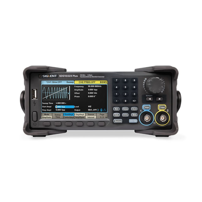
The Siglent SDG1032X Plus is a high-performance dual-channel function/arbitrary waveform generator with a 30 MHz max frequency, 16-bit resolution, and 1 GSa/s sampling rate for superior signal fidelity.
It features TrueArb for low-distortion waveforms, EasyPulse for jitter-free pulses, and robust sequence playback. With ±10 V amplitude, a 4.3" display, and versatile modulation, it's a reliable choice for engineers and researchers.
Features
Dual Channels: Independent output with maximum frequency of 30 MHz
High Sampling Rate: 1 GSa/s for precise waveform generation
High Vertical Resolution: 16-bit resolution for accurate signal reproduction
TrueArb Technology: Generates low-distortion arbitrary waveforms with high fidelity
EasyPulse Technology: Produces jitter-free square and pulse signals with fine control over rise/fall times
Arbitrary Waveform Length: Supports up to 8 Mpts per channel for complex waveform design
Wide Amplitude Range: ±10 V maximum output amplitude
Built-in Modulation Functions: AM, FM, PM, PWM, PSK, FSK, ASK, and more
Multi-Pulse Output: Enables measurement of power equipment switching parameters
PRBS Pattern Generation: Supports up to 40 Mbps for advanced testing needs
Sweep and Burst Modes: Flexible test capabilities with adjustable parameters
Sequence Playback Function: Stores and plays back complex waveforms efficiently
Frequency Counter: Measures frequencies up to 200 MHz with high precision
User-Friendly Display: 4.3" color LCD with a clear interface
Remote Control Support: Built-in WebServer for control via a web browser
Compact Design: Portable and space-saving form factor
Specifications
Bandwidth
30 MHz
Channels
2
Sampling rate
1 GSa/s (4x Interpolation)
Vertical resolution
16 bits (per channel)
Waveform length
8 Mpts
Max. amplitude
±10 V
Display
4.3" color TFT LCD (480 x 272)
Interfaces
USB Host, USB Device, LAN
Dimensions
260 x 107 x 296 mm
Weight
4.35 kg
Included
1x Siglent SDG1032X Plus Arbitrary Function Generator
1x Power Cord
1x USB Cable
1x Guarantee Card
1x Quick Start Guide
Downloads
Datasheet
User Manual
Programming Guide
Software
En moins de 100 lignes de code par projet avec les cartes Feather Sense et Clue Express d'Adafruit
Le langage de programmation Python est apprécié par les pédagogues parce que sa syntaxe le rend facile à comprendre. Il s'est également imposé chez les informaticiens expérimentés. La société Adafruit a développé une version spéciale de Python pour l'embarquer sur les microcontrôleurs à 32 bits : CircuitPython.
Ce livre permettra au lecteur de s'initier à la programmation en CircuitPython sur deux cartes : Feather BlueFruit Sense (également appelée Feather nRF52840 Sense) et CLUE nRF52840 Express. Chacune est animée par le SoC nRF52840 de NORDIC avec une architecture à 32 bits.
Pour ce voyage dans le monde de la programmation embarquée, l'auteur sort du chemin classique, à savoir un cours complet sur la programmation orientée objet appliquée à ce langage. Il préfère emmener le lecteur directement sur le terrain avec des projets qui mettent en oeuvre les cartes et différents périphériques. Plus d'une quarantaine d'exemples et de montages permettent de découvrir la richesse de CircuitPython. Toutefois l'auteur s'est imposé une limite pour ne pas décourager les novices : le code de chaque projet ne dépasse jamais la centaine de lignes. Pour ce qui est du matériel, là aussi la simplicité domine : aucun programmateur, un simple PC suffit ; aucun soudage grâce au câblage sur platine d'essai. Les cartes d'extension FeatherWing à enficher sur la Feather nRF52840 Sense permettent de démultiplier ses fonctions : matrice de LED, enregistreur de données, écran à encre électronique, écran OLED, écran TFT, commande de moteurs, audio, relais…
Toutes les étapes (assemblage des différents composants, installation des bibliothèques requises, programmation, tests…) sont expliquées en détail. Le code des différents exemples et projets est disponible sur Github. Le résultat de chaque projet est même présenté sur de courtes vidéos disponibles sur YouTube.
À la fin de sa lecture, le nouveau Pythonien pourra facilement approfondir les notions abordées et donner vie à ses propres projets grâce aux outils qu'il aura essayés.
Ce livre s'adresse aux lycéens et étudiants ainsi qu'à toute la communauté des makers.
Chaîne YouTube de l'auteur :
YouTube (Michaël Bottin)