
Search results for "USB OR serial OR hub"
-

Elektor Academy Pro ESP32 with Arduino C/C++ (Programming Course)
This complete ESP32 microcontroller programming course features a textbook, a component kit, hands-on projects, and a comprehensive online course with simulations. It is ideal for step-by-step learning of embedded systems programming with Arduino using a practical, hands-on approach. A Practical Introduction to Embedded Systems with the ESP32 This course is designed for people who are new to embedded systems and looking for a structured, example-driven way to get started. A kit of parts comprising LEDs and resistors, switches, sensors and actuators, displays, a breadboard and wires, and more is included. These are used in the course to illustrate example applications. No prior experience with Arduino or embedded development is required. Each section features hands-on examples and mini projects designed to reinforce key concepts and inspire deeper exploration. By the end of the course, you’ll be able not only to reproduce the examples but also to build on them with your own ideas and applications. What Will You Learn? Microcontroller programming with the ESP32 using the Arduino IDE Working with Digital I/O, read buttons and encoders, control LEDs and relays Read analog inputs, voltages, and analog sensors Generating analog output signals and PWM Use serial communication like UART, I²C and SPI to control displays and read digital sensors and SD cards Managing time Working with interrupts Real-time sensor input and control via buttons, LEDs, and displays Control actuators like relays and servo motors Who Is It For? Students and self-learners exploring embedded systems Makers and IoT enthusiasts looking to improve their hardware skills Educators and trainers seeking ready-to-teach material What's Inside the Box? Access to the full course on the Elektor Academy Pro Learning Platform ESP32 microcontroller board + USB cable Book: Programming Microcontrollers in C/C++ Using Arduino Downloadable project files for every module Component Box: 2× LED, red, 5 mm LED, green, 5 mm 3× Resistor, 470 Ω, 0.25 W LDR Potentiometer, 10 kΩ, linear Pushbutton Rotary encoder module Relay module DHT22 Humidity & Temperature Sensor TM1637-compatible 4-digit 7-segment display MPU-6050 IMU with headers SSD1306-compatible I²C OLED display Micro SD card adapter with header Buzzer SG90 Micro Servo ILI9341-compatible SPI 240×320 TFT display 20× Jumper wires Breadboard All Programming Courses (and differences in content) Course Arduino Raspberry Pi Pico with Arduino C/C++ ESP32 with Arduino C/C++ Raspberry Pi Pico with MicroPython ESP32 with MicroPython Online Course Access to Arduino Course Access to Pico with Arduino C/C++ Course Access to ESP32 with Arduino C/C++ Course Access to Pico with MicroPython Course Access to ESP32 with MicroPython Course Board Uno R3 Raspberry Pi Pico ESP32 Raspberry Pi Pico ESP32 Book Programming Microcontrollers in C/C++ Using Arduino Programming Microcontrollers in C/C++ Using Arduino Programming Microcontrollers in C/C++ Using Arduino Programming Microcontrollers in MicroPython Programming Microcontrollers in MicroPython Kit 40-piece Component Box 40-piece Component Box 40-piece Component Box 40-piece Component Box 40-piece Component Box
€ 69,95
Members: € 62,96
-
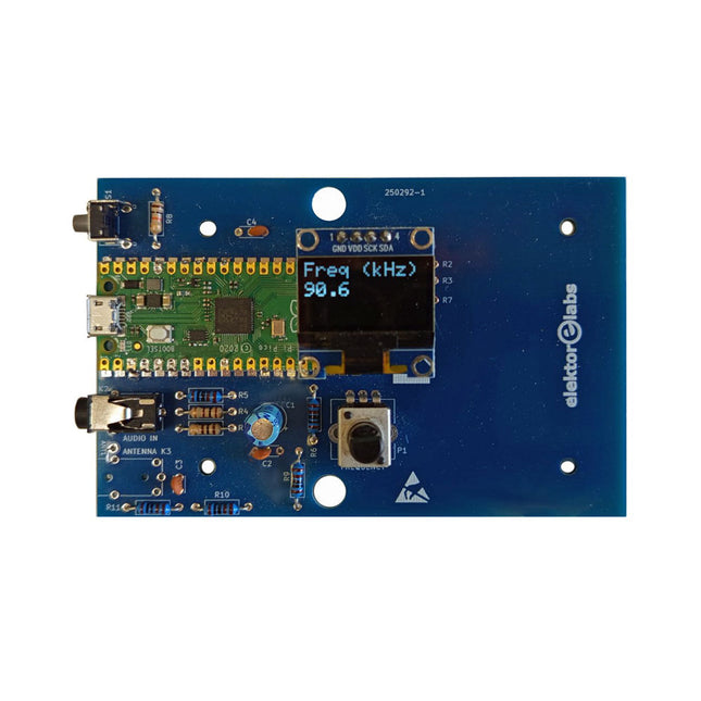
Elektor Labs Elektor AM Transmitter Kit
Build Your Own Vintage Radio Broadcaster The Elektor AM Transmitter Kit allows streaming audio to vintage AM radio receivers. Based on a Raspberry Pi Pico microcontroller module, the AM Transmitter can transmit on 32 frequencies in the AM band, from 500 kHz up to 1.6 MHz in 32 steps of approx. 35 kHz. The frequency is selected with a potentiometer and shown on a 0.96" OLED display. A pushbutton allows toggles the transmitting mode between On and Off. The range of the transmitter depends on the antenna. The onboard antenna provides a range of a few centimeters, requiring the AM Transmitter to be placed close to or inside the radio. An external loop antenna (not included) can be connected to increase the range. The Elektor AM Transmitter Kit comes as a kit of parts that you must solder to the board yourself. Features The board is compatible with a Hammond 1593N enclosure (not included).A 5 VDC power supply with micro-USB connector (e.g., an old phone charger) is needed to power the kit (not included). Current consumption is 100 mA. The Arduino software (requiring Earle Philhower’s RP2040 Boards Package) for the Elektor AM Transmitter Kit plus more information is available at the Elektor Labs page of this project. Component List Resistors R1, R4 = 100 Ω R2, R3, R8 = 10 kΩ R5, R6, R9, R10, R11 = 1 kΩ R7 = optional (not included) P1 = potentiometer 100 kΩ, linear Capacitors C1 = 22 µF 16V C2, C4 = 10 nF C3 = 150 pF Miscellaneous K1 = 4×1 pin socket K2, K3 = 3.5 mm socket Raspberry Pi Pico pushbutton, angle mount 0.96" monochrome I²C OLED display PCB 150292-1
€ 29,95
Best Price
-
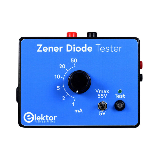
Elektor Zener Diode Tester
The Elektor Zener Diode Tester is essentially a constant-current source that can be switched in steps from 1 to 50 mA. It can be used to test Z-diodes up to a maximum of 54 V. Thanks to a 60-V step-up converter, the device can be powered by the usual 5 to 12 V. The principle of this tester is straightforward. A Z-diode or other DUT (device under test, such as an LED) is biased by an adjustable current source. The voltage across the DUT can be measured with a multimeter. The voltage of most (small) Z-diodes is specified at a current of 5 mA. Depending on the application, the voltage at other currents can also be of interest. That is why six current settings are available: 1, 2, 5, 10, 20, and 50 mA. LEDs are often specified at a current of 20 mA. What can be tested is: Whether a Z-diode is defective (short circuit or high impedance). Whether a Z-diode exhibits the correct Z-voltage. How a Z-voltage changes with different currents. What exact voltage is present at an integrated voltage reference. Whether LEDs in a series chain differ in brightness (hence the 20 mA current). What the current gain is for different base currents in (power) transistors. The kit contains all parts listed in the bill of materials including PCB and enclosure. Specifications Supply voltage 5…12 V/2 A (USB-C) Supply current (Itest = 50 mA) 1.1 A @ 5 V / 412 mA @ 12 V Selectable currents 1, 2, 5, 10, 20, and 50 mA Max. test voltage >54 V @ Itest ≥1 mA Max. output voltage 60 V @ Itest = 0 mA Voltage limit at 5 V 4.5 V @ Itest = 1 mA / 5.18 V @ Itest = 50 mA Enclosure dimensions 110 x 82 x 44 mm PCB size 105.4 x 67.3 mm Connections 4 mm banana sockets for multimeter 2 mm banana sockets for test clips USB-C socket for power supply Included Resistors R1 = 3.3 kΩ, 600 mW, 1% R2 = 0.15 Ω, 1 W, 5%, LS 12.7 mm, ø 3.5 mm R3, R8 = 180 Ω, 600 mW, 1% R4, R6, R16 = 1 kΩ, 600 mW, 1% R5, R19 = 47 kΩ, 600 mW, 1% R7 = 3.9 kΩ, 1 W, 5%, LS 12.7 mm, ø 3.5 mm R9, R10, R12 = 10 kΩ, 600 mW, 1% R11, R13 = 100 Ω, 600 mW 1% R14 = 249 Ω, 600 mW, 1% R15 = 499 Ω, 600 mW, 1% R17 = 2.49 kΩ, 250 mW, 1% R18 = 4.99 kΩ, 250 mW, 1% Capacitors C1 = 470 uF / 35 V, 20%, Ir = 1.86 A, ø 12.5 mm, LS 5 mm, ESR = 0.038 Ω (Panasonic EEUTP1V471) C2 = 1 uF / 100 V, 10%, X7R, LS 5 mm C3 = 2.2 nF / 50 V, 10%, X7R, LS 5 mm C4, C7 = 100 nF / 100 V, 10%, X7R, LS 5 mm C5 = 100 uF / 100 V, 20%, ø 14 mm max., LS 5 mm C6 = 1 nF / 100 V, 10%, X7R, LS 5 mm Inductor L1 = 100 uH, Irms = 2.4 A, Isat = 3.5 A, 0.09 Ω, radial, pitch 2.5/5/10 mm, ø 14 mm max. (Kemet SBC8-101-242) Semiconductors D1 = MUR120G, DO-41 D2, D4 = STPS3150RL, DO-201AD D3 = Z-diode, 18 V, 1.3 W (BZX85C18) D5 = Z-diode, 5.1 V, 0.5 W (1N5231B) LED1 = LED in pushbutton S1 LED2 = LED, green, 3 mm IC1 = MC34063, DIP-8 IC2 = LM4040BIZ-5.0/NOPB, TO-92 (TO-226AA-3) IC3 = TL051CP, DIP-8 T1 = BC327.25, TO-92 T2 = STP40NF10L, TO-220 T3 = IRF9510PBF, TO-220 T4 = 2N7000, TO-92 Others K1, K2, S1, S3 = 2-way screw terminal block, LS 3.5 mm, max. 1.5 mm² connected to K1 = USB-C socket, 30 V/3 A, chassis mounted, wired, 9 x 16 mm connected to K2 = Banana Connector, 2 mm, Socket, 60 VDC, Panel Mount, red (Multicomp 24.102.1) connected to K2 = Banana Connector, 2 mm, Socket, 60 VDC, Panel Mount, black (Multicomp 24.102.2) Test clip, red, 30 VAC/60 VDC (Hirschmann 931467101) Test clip, black, 30 VAC/60 VDC (Hirschmann 931467100) S1 = Pushbutton, panel mount, SPST-NO, 30 DC/100 mA, with red LED S2 = Rotary Switch, 6 position, 2 pole, 30°, 250 V/150 mA S3 = Toggle switch, panel mount, SPDT, solder lugs, 28 VDC T2, T3 = Heat sink, 15°C/W, FK 214 SA-CB Enclosure Hammond 1591XXSSBK, ABS, 110 x 82 x 44 mm Knob for S2, round shaft 6 mm, ø 21 mm, with indicator line (Multicomp CP-LB21-6-6D) 4 x Self-tapping screw #4-1/4", carbon steel, pan head Banana plug, red, 2 mm, 60 VDC (Multicomp 25.205.1) Banana plug, black, 2 mm, 60 VDC (Multicomp 25.205.2) Banana socket, black 4 mm, panel mount Banana socket, red 4 mm, panel mount for LED1, LED2 = Pin header, 1 x 2, vertical, pitch 2.54 mm for LED1, LED2 = Pin socket, 1 x 2, vertical, pitch 2.54 mm for T2, T3 = M3 screw, 10 mm, steel, pan head 2 x M3 washer, plain, steel 4 x M3 nut for IC1, IC3 = DIP-8 socket Wire, black, 0.25 mm² (24 AWG), stranded 14 x 0.15 mm, 1 m Wire, red, 0.25 mm² (24 AWG), stranded 14 x 0.15 mm, 1 m PCB 250772-1 v1.1 Links Article Elektor Labs
€ 79,95
Best Price
-
Raspberry Pi Foundation Raspberry Pi RP2040 Microcontroller (10 pcs)
Specifications Dual ARM Cortex-M0+ @ 133 MHz 264 kB on-chip SRAM in six independent banks Support for up to 16 MB of off-chip Flash memory via dedicated QSPI bus DMA controller Fully-connected AHB crossbar Interpolator and integer divider peripherals On-chip programmable LDO to generate core voltage 2x on-chip PLLs to generate USB and core clocks 30x GPIO pins, 4 of which can be used as analogue inputs Peripherals 2x UARTs 2x SPI controllers 2x I²C controllers 16x PWM channels USB 1.1 controller and PHY, with host and device support 8x PIO state machines What you'll get 10x bare RP2040 chips
€ 7,95€ 3,95Best Price
-

FNIRSI FNIRSI HT-P1B Pro Mini Hot Plate (150 W)
The FNIRSI HT-P1B Pro is a compact mini hot plate designed for PCB soldering, desoldering, and SMD rework. With up to 150 W of heating power, precise PID temperature control, and an adjustable temperature range of 100°C to 350°C, it delivers fast and stable heating for electronics projects. The 50 x 50 mm heating surface is ideal for small PCBs and electronic components. Two operating modes – constant temperature heating and simulated reflow soldering – provide flexibility for different applications. A 1.44-inch color display, three temperature presets, and built-in safety features ensure convenient operation. With DC and USB-C PD 3.1 support, a compact design, and an included 100 W USB-C charger, the HT-P1B Pro is a practical tool for makers, electronics enthusiasts, and repair professionals. Features Up to 150 W Heating Power: Fast heating with adjustable power settings from 30 W to 150 W. Precise PID Temperature Control: Adjustable range from 100°C to 350°C with ±3°C temperature stability. Dual Operating Modes: Constant temperature heating and simulated reflow soldering. 50 × 50 mm Heating Surface: Ideal for small PCBs, SMD soldering, and component rework. Flexible Power Input: DC 12-28 V (up to 150 W) and USB-C PD 3.1 (up to 140 W). Three Temperature Presets: Quick access to frequently used temperature settings. 1.44-inch Color Display: Shows temperature, voltage, power, heating time, and operating status. Built-in Safety Features: Over-temperature, low-voltage, prolonged-heating, and tilt protection. Specifications Power Input DC 12-28 V / USB-C PD Power Range 30-150 W Standby Power 1.6 W Temperature Range 100-350°C (212-662°F) Temperature Stability ±3°C Heating Area 50 x 50 mm Display 1.44" Color Screen Tilt Detection 20°-50° Protocol PD 3.1 Dimensions 68.8 x 81.8 x 44.5 mm Weight 157 g Included 1x FNIRSI HT-P1B Preheating Station 1x FNIRSI 100 W PD GaN Charger (EU) 1x FNIRSI 100 W USB-C Fast-charging Cable 1x Heat-Resistant Silicone Cover 1x Storage Case 1x Manual Downloads Manual
€ 84,95
Best Price
-
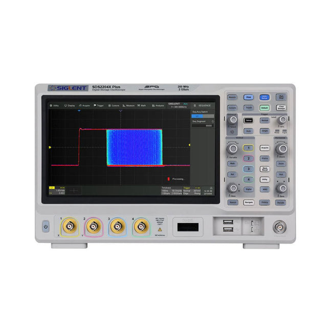
Siglent Siglent SDS2204X Plus 4-ch Oscilloscope (200 Mhz)
Siglent's SDS2000X Plus series Digital Storage Oscilloscopes are available in bandwidths of 100 MHz, 200 MHz, and 350 MHz, have a maximum sample rate of 2 GSa/s, a maximum record length of 200 Mpts/ch, and up to 4 analog channels + 16 digital channels mixed-signal analysis ability. The SDS2000X Plus series employs Siglent’s SPO technology with a maximum waveform capture rate of up to 120,000 wfm/s (normal mode, up to 500,000 wfm/s in Sequence mode), 256-level intensity grading display function plus a color temperature display mode. It also employs an innovative digital trigger system with high sensitivity and low jitter. The trigger system supports multiple powerful triggering modes including serial bus triggering. History waveform recording, Sequence acquisition, Search and Navigate functions allow for extended waveform records to be captured, stored, and analyzed. An impressive array of measurement and math capabilities, options for a 50 MHz waveform generator, as well as serial decoding, mask test, bode plot, and power analysis are also features of the SDS2000X Plus. A 10-bit acquisition mode helps to satisfy applications that require more than 8-bit resolution. The large 10.1’’ capacitive touch screen supports multi-touch gestures, while the remote web control, mouse and external keyboard support greatly improve the operating efficiency of the SDS2000X Plus. Features 100 MHz, 200 MHz, 350 MHz (upgradable to 500 MHz) models Real-time sampling rate up to 2 GSa/s Record length up to 200 Mpts Serial bus triggering and decoder, supports I²C, SPI, UART, CAN, LIN, CAN FD, FlexRay, I²S and MIL-STD-1553B Provide 10 bit mode, Vertical and Horizontal Zoom Capacitive touch screen supports multi-touch gestures Siglent SDS2000X Plus Oscilloscopes SDS2102X Plus SDS2104X Plus SDS2204X Plus SDS2354X Plus Bandwidth 100 MHz 100 MHz 200 MHz 350 MHz Channels 2 4 4 4 Real-time sampling rate 2 GSa/s 2 GSa/s 2 GSa/s 2 GSa/s Capture rate 120,000 wfm/s 120,000 wfm/s 120,000 wfm/s 120,000 wfm/s Memory depth 200 Mpts/ch 200 Mpts/ch 200 Mpts/ch 200 Mpts/ch Included Siglent SDS2204X Plus Oscilloscope Passive probes Power cord USB cable Manual Downloads Datasheet Manual Quick guide Manual Firmware
€ 1.838,23
-
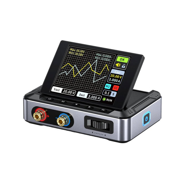
FNIRSI FNIRSI DPS150 DC Power Supply (150 W)
The FNIRSI DPS150 is a high-performance adjustable DC power supply that features a USB-C input interface and multiple power supply modes, allowing precise adjustment of output voltage (0-30 V) and current (0-5 A). It provides efficient, low-consumption, and stable output, equipped with multiple safety protection functions including overvoltage, overcurrent, overload, overheating, and reverse connection. It can be flexibly applied to serial connection of multiple devices, with rich and user-friendly display and operation, compact and portable design, meeting various application needs. Features 30 V, 5 A, 150 W variable DC power with 0.01 V, 0.001 A precision, CC/CV modes, and <20 mV ripple to protect sensitive electronics. Supports PC, QC, and DC inputs with programmable outputs and 6 preset voltage/current settings. Compatible with 4 mm banana plugs, U-shaped terminals, and copper wires for various equipment. 8 safety mechanisms including overvoltage, current, short circuit, and overheating protection. 2.8-inch HD IPS screen with 90° flip, numerical and curve displays for easy monitoring. Small, space-saving design for use in labs, repairs, and DIY projects. Specifications Input Voltage 5~32 V DC Input Current 100 mA-5 A Output Voltage 0-30 V Output Current 0~5 A Output Power 0-150 W Input Way PD fast charger QC fast charger Power bank DC power adapters Operating Environment 0-40°C Load Regulation 0.49% Full Load Efficiency 96.30% Display 2.8 inch (320 x 240) Dimensions 106 x 76 x 28 mm Weight 178 g Included 1x DPS150 Power Supply 2x Alligator clip wires (black & red) 1x Micro USB cable 1x Manual Downloads Manual Firmware V0.0.1
€ 59,00
-

Elektor Digital Logic Analyzer im Einsatz (PDF)
USB-Logikanalysatoren am PC mit Arduino, Raspberry Pi und Co Schritt-für-Schritt-Anleitungen führen Sie in die Analyse moderner Protokolle von I²C, SPI, UART, RS-232, NeoPixel, WS28xx, HD44780 und 1-Wire ein. Anhand von zahlreichen Experimentierschaltungen mit dem Raspberry Pi Pico, Arduino Uno und dem Bus Pirate üben Sie die praxisnahe Anwendung gängiger USB-Logikanalysatoren ein. Alle in diesem Buch vorgestellten Experimentierschaltungen wurden vollständig getestet und sind funktionsfähig. Die notwendigen Programmlistings sind enthalten, es sind keine besonderen Programmier- oder Elektronikkenntnisse für diese Schaltungen notwendig. Es werden die Programmiersprachen MicroPython und C mit den Entwicklungsumgebungen Thonny und Arduino IDE eingesetzt. Dieses Buch verwendet mehrere Modelle flexibler und weit verbreiteter USB-Logikanalysatoren und zeigt die Stärken und Schwächen jeder Preisklasse. Sie werden kennenlernen, welche Kriterien für Ihre Arbeit wichtig sind und in der Lage sein, das für Sie passende Gerät zu finden. Egal ob Arduino, Raspberry Pi oder Raspberry Pi Pico: Die abgebildeten Beispielschaltungen ermöglichen einen schnellen Start in die Protokollanalyse und können auch als Grundlage für eigene weitere Experimente dienen. Sie werden alle wichtigen Begriffe und Zusammenhänge kennenlernen, eigene Experimente durchführen, selbstständig Protokolle analysieren und nach der Lektüre dieses Buches – im Bereich der digitalen Signale und Protokolle – ein umfassendes Wissen aufgebaut haben.
€ 32,80
Members: € 29,52
-
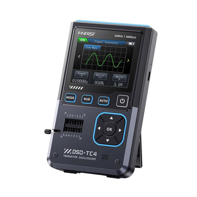
FNIRSI FNIRSI DSO-TC4 (3-in-1) Oscilloscope (10 MHz) + Transistor Tester + Signal Generator
The FNIRDSI DSO-TC4 is a multifunctional transistor oscilloscope that is both comprehensive and practical. It is designed for use in maintenance and R&D applications, integrating an oscilloscope, transistor tester, and signal generator into a single device. Features Equipped with a 2.8-inch TFT color screen for a clear and intuitive display Built-in high-capacity rechargeable lithium battery (1500 mAh) with a standby time of up to 4 hours Compact and lightweight, ideal for mobile use Specifications Oscilloscope Analog Bandwidth 10 MHz Real-Time Sampling Rate 48 MSa/s Input Impedance 1 MΩ Coupling Mode AC/DC Test Voltage Range 1:1 Probe: 80 Vpp (+40 V) 10:1 Probe: 800 Vpp (+400 V) Vertical Sensitivity 10 mV/div~10 V/div (X1 range) Vertical Displacement Adjustable with indication Time Base Range 50ns~20s Trigger Mode Auto/Normal/Single Trigger Type Rising edge, Falling edge Trigger Level Adjustable with indication Waveform Freeze Yes (HOLD function) Automatic Measurement Max, Min, Avg, RMS, Vpp, Frequency, Cycle, Duty Cycle Component Tester Transistor Amplification factor "hfe"; Base-Emitter voltage "Ube", Ic/Ie, Collector-Emitter reverse leakage current "Iceo", Ices, Forward voltage drop of protection diode "Uf" Diode Forward voltage drop <5 V (Forward voltage drop, Junction capacitance, Reverse leakage current) Zener Diode 0.01~32 V Reverse Breakdown Voltage (K-A-A Test Area) Field-Effect Transistor (FET) JFET: Gate capacitance "Cg", Drain current Id under "Vgs", Forward voltage drop of protection diode "Uf" IGBT: Drain current Id under Vgs, Forward voltage drop of protection diode Uf MIOSTET: Threshold voltage "Vt", Gate capacitance "Cg", Drain-Source resistance "Rds", Forward voltage drop of protection diode "Uf" Unidirectional SCR Trigger voltage <5V, Gate level (Gate voltage) Bidirectional SCR Trigger current <6mA (Gate voltage) Capacitor 25pF~100mF, Capacitance value, Loss factor "Vloss" Resistor 0.01Ω~50MΩ Inductor 10μH~1000μH, DC resistance DS18B20 Temperature sensor, Pins: GND, DQ, VDD DHT11 Temperature and humidity sensor, Pins: VDD, DATA, GND Signal Generator Output Waveform Supports 13 waveform outputs Waveform Frequency 0-50 KHz Square Wave Duty Cycle 0-100% Waveform Amplitude 0.1-3.0 V General Display 2.8-inch TFT color screen Backlight Brightness adjustable Power Supply USB-C (5 V/1 A) Battery 3.7 V/1500 mAh Languages English, German, Spanish, Portuguese, Russian, Chinese, Japanese, Korean Dimensions 90 x 142 x 27.5 mm Weight 186 g Included 1x FNIRSI DSO-TC4 (3-in-1) Oscilloscope (10 MHz) 1x P6100 Oscilloscope probes (10X) 1x Alligator clip probe 3x Test hooks 1x Adapter 1x USB-C charging cable 1x Manual Downloads Manual Firmware V0.0.7 (+V1.0.9)
€ 74,95
Best Price
-

SEQURE SEQURE HT140 (2-in-1) SMD Soldering & Desoldering Tweezers
The SEQURE HT140 is a highly versatile 2-in-1 soldering tool that combines the functionality of hot tweezers and a soldering iron. It is specifically engineered for precise SMD soldering and desoldering tasks. With independent control for single-sided heating, it operates as a traditional soldering iron when fitted with a standard tip. When configured for dual-sided heating, it transforms into hot tweezers – perfect for the efficient and accurate removal of SMD components. Features Working Temperature: 50-500°C (122-932°F) Supports multiple power inputs: PD 3.1/3.0/2.0, QC 3.0/2.0, (5-28 V DC), LiPo batteries, and power adapters. The HT140 combines hot tweezers and a soldering iron, with independent single- or dual-sided heating. Use it as a soldering iron with a tip, or as hot tweezers for easy SMD desoldering. Voltage and current can be adjusted based on the power source. Features dual temperature control, presets, quick temperature increase, and fine-tuning. 128 x 32 OLED screen with adjustable brightness, and orientation. Switchable °C/°F. High-precision heating element with ±1% accuracy. Melts solder in just 2 seconds. Smart standby, sleep, and wake-up functions extend tip lifespan and boost efficiency. Supports temperature calibration and compensation for precise work. Includes a 1.5 m heat-resistant PD 150 W silicone cable and a sturdy all-metal HT Station. Swappable tips and adjustable angles for various SMD soldering tasks. Specifications Working Voltage 5-28 V DC Maximum Power 140 W Working Temperature 50-500°C (122-932°F) Tin Melting Time 2s Interface Type USB-C, DC5525 Power Supply PD 3.1/3.0/2.0, QC 3.0/2.0, 28 V DC max Display 128 x 32 OLED Firmware Upgrade Yes Menu Languages English, Russian, Chinese Dimensions 160 x 27 x 17.5 mm Weight 50 g Included 1x SEQURE HT140 Host 2x HT140-IS Tapered Curved Desoldering Tips 1x HT Station 1x Accessory Package 1x Storage Bag 1x 65 W PD Power Supply (EU, UK & US) 1x 24 W PD Silicone Wire (1.5 m) 1x GND Wire Accessory Kit (1.8 m) Downloads Manual Firmware V1.04
€ 99,95
Best Price
-

JOY-iT Joy-Pi Note 2 (incl. Raspberry Pi 5, 8 GB)
The Joy-Pi Note 2 is a portable, all-in-one electronics experimentation and learning platform, fully compatible with the Raspberry Pi 4 and 5. Combining an 11.6-inch IPS display, a detachable wireless keyboard, and a compact, robust housing, it provides a flexible environment for electronics development, programming, and education. With more than 45 hands-on courses and projects, the Joy-Pi Note 2 supports learning and experimentation with Python, Scratch, robotics, and IoT applications. Its integrated learning platform provides step-by-step instructions, making it suitable for beginners, students, educators, and experienced makers. The system features over 22 integrated sensors and modules, including temperature, light, motion, and distance sensors, as well as LED displays and motor interfaces. Additional connectivity options, including USB-C and GPIO expansion interfaces, allow users to develop and test their own projects. With support for the Raspberry Pi 5, the Joy-Pi Note 2 also benefits from improved processing power and graphics performance, making it a versatile platform for electronics education, prototyping, and advanced experimentation. Features Complete Electronics Experimentation Kit All-in-One Learning and Experimentation Platform Compatible with Raspberry Pi 4 & 5 Pre-installed Interactive Learning Platform Detachable Wireless Keyboard Integrated Storage Compartment for Power Bank and Accessories Specifications Display 11.6" LCD Display Camera 2 MP Learning platform 45+ courses & projects Displays 7-segment display, 16x2 display, 1.8" TFT display, 0.96" OLED display, 8x8 RGB matrix Power supply 5 V/5 A, USB-C Displays 7-segment display, 16x2 LCD module, 8x8 RGB matrix Sensors DHT temperature & humidity sensor, tilt sensor, motion sensor, sound sensor, touch sensor, RFID module, light sensor, ultrasonic sensor Motors Servo interface, stepper motor interface, vibration motor Control system Joystick, 4x4 button matrix, Raspberry Pi & PCV connection switch, motion sensor sensitivity controller, sound sensor sensitivity controller, 16x2 LCD module brightness controller Miscellaneous Relay, fan, GPIO extension, GPIO LED indicator, breadboard, IO/ ADC/I²C/UART extension interface, infrared sensor interface, buzzer, display driver Accessories RFID chip, RFID card, power supply unit, servo motor, stepper motor, infrared receiver, infrared remote control, DC motor with fan attachment, screwdriver, microSD card (32 GB), SD card reader, electronic accessories, wireless mouse, wireless keyboard Dimensions 291 x 190 x 46 mm Weight 1.3 kg Included Joy-Pi Note 2 Notebook Raspberry Pi 5 (8 GB RAM) Accessories USB-C power supply unit Quick start guide Downloads Joy-Pi website Datasheet
€ 449,00
Best Price
-

Elecrow Elecrow AI Starter Kit for Jetson Orin Nano
All-in-One AI Learning and Development Platform for Edge Intelligence This NVIDIA Jetson-based AI Starter Kit is a versatile platform for learning, development, and hands-on experimentation in Edge AI. Designed for use with the NVIDIA Jetson Orin Nano, the kit combines an 11.6-inch IPS display, an 8-megapixel pan-tilt camera, and an AI voice interaction system. It includes 30 functional modules and 38 carefully designed Python courses that progress from beginner to advanced level. The course content covers Python fundamentals, sensor technology, AI vision, and image recognition. With step-by-step practical exercises ranging from basic programming to real-world computer vision applications, this kit provides an ideal platform for students, makers, developers, and anyone looking to explore artificial intelligence and edge computing. Please note: The NVIDIA Jetson Orin Nano is not included. Features Designed for the NVIDIA Jetson Orin Nano AI voice interaction module 8 MP camera with pan-tilt control Supports object and face tracking No soldering or complex wiring required Built-in 11.6-inch IPS display 30 functional modules 38 step-by-step Python lessons I²C, UART, and GPIO expansion interfaces Portable carrying case included Specifications Main Processor Jetson Orin Nano Number of Sensors 30 Sensor Board Design Integrated sensor board, no soldering or complex wiring required Screen 11.6-inch IPS Screen Screen Resolution 1366 x 768 Camera IMX219 8MP Expansion Interfaces 2x I²C, 1x UART, 1x IO D13, 1xIO D12 Programming Environment Based on Python Number of Tutorials 38 creative tutorials Target Audience Students, teachers, hardware enthusiasts Application Scenarios Ideal for learning AI programming, Jetson Orin Nano basics Dimensions 300 x 200 x 100 mm Module List Module Quantity Temperature & Humidity Sensor 1 pcs Button 4 pcs Ultrasonic Ranging Sensor 1 pcs Light Sensor 1 pcs Linear Potentiometer 1 pcs Buzzer 1 pcs LCD 1 pcs Infrared Remote 1 pcs Relay 1 pcs NFC 1 pcs PIR Motion Sensor 1 pcs Joystick 1 pcs 4-Digital Display 1 pcs LED 1 pcs Microphone 1 pcs Speaker 1 pair Vibration Motor 1 pcs Touch Sensor 1 pcs 8x8 RGB Matrix 1 pcs Atmospheric pressure sensor 1 pcs Tilt Switch 1 pcs Stepper Motor 1 pcs Accelerometer & Gyro 1 pcs Gas Sensor (MQ2) 1 pcs Hall Sensor 1 pcs Rotary Encoder 1 pcs U-shaped photoelectric switch 1 pcs NTC 1 pcs Servo 2 pcs Monocular camera 1 pcs Included 1x Elecrow AI Starter Kit for Jetson Orin Nano 1x IR Remote Control 1x NFC Card 1x 128 GB SD Card 1x 40-pin GPIO Cable 2x 22-pin FPC Cable 2x 24-pin FPC Cable 1x Jetson DP & USB Adapter Board Not included NVIDIA Jetson Orin Nano Downloads Manual Wiki OpenClaw Install and Config Guide
€ 249,00
Members: € 224,10


