Elektor GREEN en GOLD leden kunnen deze uitgave hier downloaden.
Nog geen lid? Klik hier om een lidmaatschap af te sluiten.
PbMonitor v1.0Een accu-bewakingssysteem voor UPS en energieopslag toepassingen
Zonne-laadregelaar met MPPT (1)basisprincipes van een zonne-laadregelaar voor autonome systemen
Integrerende B-veld magnetometermet zelfgemaakte sensoren
Precies of nauwkeurig?Je instrumenten moeten het allebei zijn!
AD7124 Een precisie-ADC in de praktijkEssentieel voor Sensorsignaalconditionering
PID-regeltoolGemakkelijk PID-parameters optimaliseren
embedded world 2025
Alle begin......gaat verder met de toonregeling
Academy Pro BoxBoek + onlinecursus + hardware
Milliohmmeter adapterGebruik de nauwkeurigheid van uw multimeter
De volgende sprong in halfgeleidersVoorwaarts naar 1,4nm
Through-hole connectorenHet beste van twee werelden: THR
FrequentietellerDraagbaar en Automatische Kalibratie met GPS
Analoge metersVreemde onderdelen, de serie
Stand-alone kristaltesterhoe nauwkeurig is uw kloksignaal?
Goedkope I²C-testersluit I²C-apparaten rechtstreeks op uw PC aan
Uit het leven gegrepenwie het kleine niet eert...
2025: een AI-odysseede transformerende invloed op softwareontwikkeling
Err-lectronicsCorrecties, updates en ingezonden brieven
Raspberry Pi standalone MIDI-synthesizer (2)We verbeteren onze setup met intelligentie
Norton-getransformeerde wienbrug-oscillatorkleine verandering, grote verbetering
Test van een 10-cent-controllerde CH32V003 RISC-V microcontroller en MounRiver Studio in de praktijk
Een FPGA-gebaseerde audiospeler met equalizer (2)volumeregeling, geavanceerd mixen en een webinterface
This bundle is all about designing projects based on the 555 timer IC. The book features over 45 fully tested and documented projects. Together with the kit, which contains more than 130 through-hole components, you can build all the projects described on a breadboard. The setup also makes it easy to modify and experiment with the projects.
Over 45 Builds for the Legendary 555 Chip (and the 556, 558)
Some of the projects in the book are:
Alternately Flashing Two LEDs
Changing LED Flashing Rate
Touch Sensor On/Off Switch
Switch On/Off Delay
Light-Dependent Sound
Dark/Light Switch
Tone Burst Generator
Long Duration Timer
Chasing LEDs
LED Roulette Game
Traffic Lights
Continuity Tester
Electronic Lock
Switch Contact Debouncing
Toy Electronic Organ
Multiple Sensor Alarm System
Metronome
Voltage Multipliers
Electronic Dice
7-Segment Display Counter
Motor Control
7-Segment Display Dice
Electronic Siren
Various Other Projects
Kit Contents
Resistors
1x 15 kΩ
1x 68 kΩ
2x 47 kΩ
1x 82 kΩ
2x 820 Ω
1x 8.2 kΩ
3x 10 kΩ
1x 1.8 kΩ
1x 6.8 kΩ
14x 2.2 kΩ
10x 680 Ω
1x 27 kΩ
1x 5.6 kΩ
1x 560 kΩ
1x 4.7 kΩ
1x 3.3 kΩ
3x 33 kΩ
1x 36 kΩ
2x 100 kΩ
5x 1 kΩ
1x 3.9 kΩ
2x 56 kΩ
2x 12 kΩ
1x 10 kΩ potentiometer
1x 1 MΩ potentiometer
2x 50 kΩ potentiometer
3x 20 kΩ potentiometer
1x 10 kΩ potentiometer
1x 10 kΩ potentiometer
1x 50 kΩ potentiometer
1x 100 kΩ potentiometer
1x 50 kΩ potentiometer
Capacitors
1x 0.33 μF
1x 1 μF
1x 10 nF
1x 22 nF
1x 47 nF
1x 100 nF
1x 10 μF electrolytic
1x 33 μF electrolytic
2x 100 μF electrolytic
LEDs
10x 5 mm red LED
10x 3 mm red LED
3x 3 mm yellow LED
3x 3 mm green LED
1x Common-cathode 7-segment LED
Semiconductors
3x 555 timer
1x CD4017 counter
1x CD4026 counter
1x CD4011 NAND gate
4x 1N4148 diode
1x IRFZ46N MOSFET
1x Thermistor
1x Light dependent resistor (LDR)
Miscellaneous
1x Passive buzzer
1x Active buzzer
1x SG90 servo
1x 8 Ω mini loudspeaker
1x 9 V DC brushed motor
1x 5 V relay
1x 9 V battery clip
7x Pushbutton switches
1x Breadboard
1x Breadboard jumper wires
Elektor GREEN en GOLD leden kunnen deze uitgave hier downloaden.
Nog geen lid? Klik hier om een lidmaatschap af te sluiten.
De ESP-BLASTEen mini ESP32 raketdrone die ruim 100 km/u vliegt
STM32Cube Innovation-ChallengeDoe mee met je beste STM32C5-ontwerp
Wireless workshop (1)Radiomodules uitgelegd: 433 MHz CC1101 sub-GHz-transceiver
AM-zenderMet sinus- en blokgolfgenerator op Raspberry Pi Pico
AudiotronicaDe vervormingsfactor
CoffeeCallerOmroepsysteem met mesh-netwerk en Zephyr gebaseerde software
Elektor wordt 65Projecten uit voorgaande september- en oktobermaanden
Bluetooth Channel Sounding voor het volgen van objectenAfstandsmeting met centimeterprecisie voor het IoT van de volgende generatie
2026: Een AI-odysseeKwantumcomputing is geen volgende GPU
Om de cloud te beveiligen, is edge-beveiliging nodig
Eerste ervaringen met de HackRF ProPraktische tests met de nieuwe SDR-hardware
Modemupgrade van GPRS/2G naar LTE/4GEen draadloos alarmsysteem als voorbeeld
Lusvormige antenne met RF-bouwstenenDeel 1: Een zelfbouw kortegolfantenne met instelbare richtingsgevoeligheid
Internetradio naar AM-converterMet een ESP32-S3 als zender
Err-lectronics
Mioty, een overzichtFraunhofer's aanpak van LPWAN
WerkbankwijsheidPraktische tips van experts
Walter, de compacte IoT-moduleDeel 2: Toegang tot weer- en datadiensten
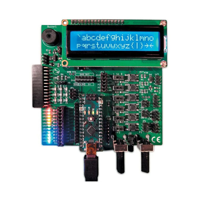
The Elektor Arduino Nano MCCAB Training Board contains all the components (incl. Arduino Nano) required for the exercises in the "Microcontrollers Hands-on Course for Arduino Starters", such as light-emitting diodes, switches, pushbuttons, acoustic signal transmitters, etc. External sensors, motors or assemblies can also be queried or controlled with this microcontroller training system.
Specifications (Arduino Nano MCCAB Training Board)
Power Supply
Via the USB connection of the connected PC or an external power supply unit (not included)
Operating Voltage
+5 Vcc
Input Voltage
All inputs
0 V to +5 V
VX1 and VX2
+8 V to +12 V (only when using an external power supply)
Hardware periphery
LCD
2x16 characters
Potentiometer P1 & P2
JP3: selection of operating voltage of P1 & P2
Distributor
SV4: Distributor for the operating voltagesSV5, SV6: Distributor for the inputs/outputs of the microcontroller
Switches and buttons
RESET button on the Arduino Nano module 6x pushbutton switches K1 ... K6 6x slide switches S1 ... S6 JP2: Connection of the switches with the inputs of the microcontroller
Buzzer
Piezo buzzer Buzzer1 with jumper on JP6
Indicator lights
11 x LED: Status indicator for the inputs/outputs LED L on the Arduino Nano module, connected to GPIO D13 JP6: Connection of LEDs LD10 ... LD20 with GPIOs D2 ... D12
Serial interfacesSPI & I²C
JP4: Selection of the signal at pin X of the SPI connector SV12 SV9 to SV12: SPI interface (3.3 V/5 V) or I²C interface
Switching output for external devices
SV1, SV7: Switching output (maximum +24 V/160 mA, externally supplied) SV2: 2x13 pins for connection of external modules
3x3 LED matrix(9 red LEDs)
SV3: Columns of the 3x3 LED matrix (outputs D6 ... D8) JP1: Connection of the rows with the GPIOs D3 ... D5
Software
Library MCCABLib
Control of hardware components (switches, buttons, LEDs, 3x3 LED matrix, buzzer) on the MCCAB Training Board
Operating Temperature
Up to +40 °C
Dimensions
100 x 100 x 20 mm
Specifications (Arduino Nano)
Microcontroller
ATmega328P
Architecture
AVR
Operating Voltage
5 V
Flash Memory
32 KB, of which 2 KB used by bootloader
SRAM
2 KB
Clock Speed
16 MHz
Analog IN Pins
8
EEPROM
1 KB
DC Current per I/O Pins
40 mA on one I/O pin, total maximum 200 mA on all pins together
Input Voltage
7-12 V
Digital I/O Pins
22 (6 of which are PWM)
PWM Output
6
Power Consumption
19 mA
Dimensions
18 x 45 mm
Weight
7 g
Included
1x Elektor Arduino Nano Training Board MCCAB
1x Arduino Nano
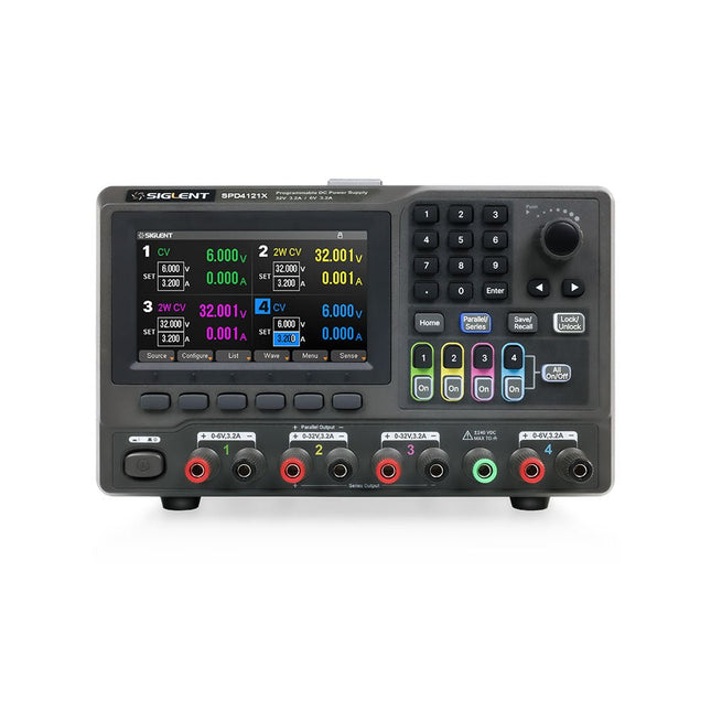
The Siglent SPD4121X is a 4-channel DC Linear Programmable Power Supply equipped with a 4.3-inch TFT-LCD display, friendly human-machine interface, and excellent performance indicators. Real-time waveform display provides engineers with an informative user interface.
SPD4121X offers a total output power of 285 W with a resolution of 1 mV/1 mA. The maximum voltage and current for each channel are as follows:
CH1: 15 V/1.5 A
CH2: 12 V/10 A
CH3: 12 V/10 A
CH4: 15 V/1.5 A
Features
Rated output power: 285 W
Rated voltage: 32 V, 12 V, 30 V
Up to four high-precision power supplies with independent controllable outputs, supporting CH2 and CH3 series and parallel connections
Clear graphical interface with waveform and timer display modes
5-digit voltage and current display with minimum resolution of 1 mV, 1 mA
Fast output response time: <50us
The high current channel support remote voltage compensation sense function. The maximum compensation voltage is 0.6 V
Overvoltage protection and overcurrent protection or safe and accurate operation
Equipped with a 4.3-inch TFT-LCD display (480 x 272 resolution)
USB and LAN standard communication
USB-GPIB module is optional
Excellent channel density with up to 4 channels in a 3U half rack package
Internal data storage for setups and parameters
Embedded Web Server with instrument communication that doesn’t require software installation
Fully SCPI programming command set support as well as a LabView driver for remote control and system automation
Specifications
SPD4323X
SPD4121X
SPD4306X
Channel Output
CH1: Voltage 0 to 6 V Current 0 to 3.2 ACH2: Voltage 0 to 32 V Current 0 to 3.2 ACH3: Voltage 0 to 32 V Current 0 to 3.2 ACH4: Voltage 0 to 6 V Current 0 to 3.2 A
CH1: Voltage 0 to 15 V Current 0 to 1.5 ACH2: Voltage 0 to 12 V Current 0 to 10 ACH3: Voltage 0 to 12 V Current 0 to 10 ACH4: Voltage 0 to 15 V Current 0 to 1.5 A
CH1: Voltage 0 to 15 V Current 0 to 1.5 ACH2: Voltage 0 to 30 V Current 0 to 6 ACH3: Voltage 0 to 30 V Current 0 to 6 ACH4: Voltage 0 to 15 V Current 0 to 1 A
Resolution
1 mV, 1 mA
1 mV, 1 mA
1 mV, 1 mA
Setting Accuracy
Voltage: ±(0.03% of reading+10) mV, Current: ±(0.3% of reading+10) mA
Voltage: ±(0.03% of reading+10) mV, Current: ±(0.3% of reading+10) mA
Voltage: ±(0.03% of reading+10) mV, Current: ±(0.3% of reading+10) mA
Readback Accuracy
Voltage: ±(0.03% of reading+10) mV, Current: ±(0.3% of reading+10) mA
Voltage: ±(0.03% of reading+10) mV, Current: ±(0.3% of reading+10) mA
Voltage: ±(0.03% of reading+10) mV, Current: ±(0.3% of reading+10) mA
Display
4.3" TFT-LCD 5-digit voltage and current display
4.3" TFT-LCD 5-digit voltage and current display
4.3" TFT-LCD 5-digit voltage and current display
Output power
240 W
285 W
400 W
Included
1x Siglent SPD4121X Power Supply
1x Power cord (EU)
1x Output test cord (3 A)
1x USB cable
1x Quick start guide
Downloads
Datasheet
Manual
Quick start
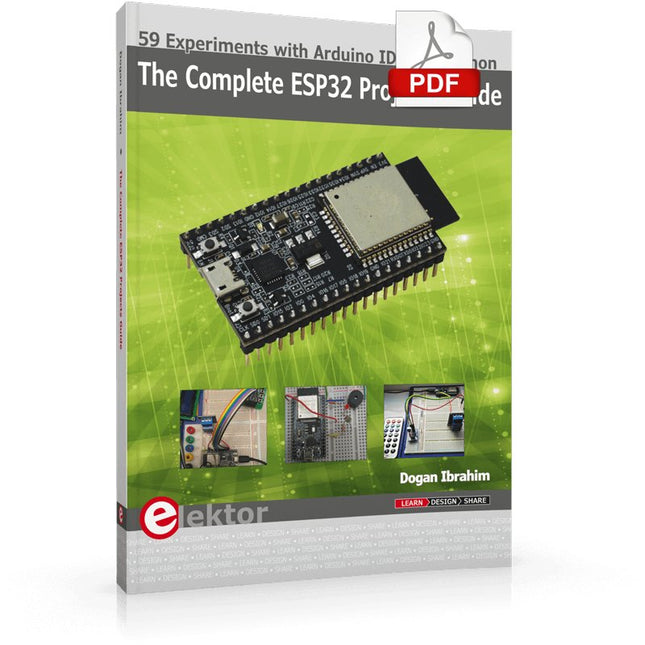
59 Experiments with Arduino IDE and Python
The main aim of this book is to teach the Arduino IDE and MicroPython programming languages in ESP32 based projects, using the highly popular ESP32 DevKitC development board. Many simple, basic, and intermediate level projects are provided in the book using the Arduino IDE with ESP32 DevKitC. All projects have been tested and work. Block diagrams, circuit diagrams, and complete program listings of all projects are given with explanations. In addition, several projects are provided for programming the ESP32 DevKitC using MicroPython. The projects provided in this book are designed to teach the following features of the ESP32 processor:
GPIOs
Touch sensors
External interrupts
Timer interrupts
I²C and I²S
SPI
PWM
ADC
DAC
UART
Hall sensor
Temperature sensor
Infrared controller
Reading and writing to SD card
Reading and writing to flash memory
RTC timer
Chip ID
Security and encryption
Wi-Fi and network programming
Bluetooth BLE programming
Communication mobile devices
Low power design
ESP-IDF programming
The projects have been organized with increasing levels of difficulty. Readers are encouraged to tackle the projects in the order given. A specially prepared hardware kit (SKU 18305) is available from Elektor. With the help of this hardware, it should be easy and fun to build the projects in this book.
Open-Source-Code mit Arduino IDE und PlatformIO
Autonomes Fahren: GPS, Accelerometer, Gyroskop
PS3-Controller
Mikrocontroller wie der Arduino und Einplatinenrechner wie der Raspberry Pi haben sich zu beliebten Komponenten entwickelt. Dritter im Bunde ist der ESP32 der Firma Espressif. Mikrocontroller dieser Baureihe zeichnen sich durch eine Vielzahl implementierter Funktionen aus, die bei einem Arduino konventioneller Prägung mit einem Atmel-AVR-Mikrocontroller erst mit weiterer Hardware möglich sind. Prominentes Beispiel sind hier die WiFi- und Bluetooth-Funktionalitäten. Gegenüber einem Raspberry Pi zeichnen sie sich durch einen deutlich geringeren Preis aus.
Allgemeine Informationen für die Realisierung eines Roboterauto-Projekts mit dem ESP32 sind leicht zu finden. Dabei handelt es sich aber oft nur um Ausführungen zu einem Teilaspekt, ohne inhaltliche oder funktionale Abstimmung. So ist nicht nur die Beschaffung der benötigten Informationen mühselig und zeitaufwändig, sie kann auch außerordentlich fehlerträchtig sein.
Ansatzpunkt dieses Buches ist, diese Lücke zu schließen. Es geht auf verschiedene Möglichkeiten eines Chassis ein, vermittelt nötige Kenntnisse und führt schrittweise von einer einfachen Motorsteuerung zu einem komplexen sensor- und sprachgesteuerten Roboterauto. Hacks rund um GPS und eine PlayStation 3 runden die Sache ab.
Inhalt
Bei der Reihenfolge der Kapitel wurde versucht – beginnend bei der Darstellung von grundlegenden Informationen – über die Lösung einfacher Aufgaben zu etwas anspruchsvolleren Techniken zu führen.
Der Mikrocontroller ESP32
Die Software erstellen
Die Stromversorgung
Rund um die Hardware
Das Chassis
Der Gleichstrommotor
Kabellose Steuerung über WiFi
Mit Sensoren Hindernisse erkennen
Eine eigene Roboterauto-App
Servo und Lichtsensor
GPS
Accelerometer / Gyroskop
PS3-Controller
Roboterauto-App
Hinweis zur Software
Die Dateien haben das Suffix (.cpp). Grund ist die Entwicklung mit PlatformIO. Mit Copy & Paste sollten sie auch in der Arduino-IDE verwendet werden können.
The FNIRSI TMP-610S is a compact 3-in-1 test instrument combining a True RMS multimeter, 10 MHz oscilloscope, and 50 kHz DDS signal generator. It is designed for electronics troubleshooting, circuit testing, and development in the lab or on the go.
The multimeter offers 60,000-count resolution and supports voltage, current, resistance, capacitance, frequency, temperature, diode, and continuity measurements. The integrated oscilloscope provides real-time waveform analysis at up to 48 MSa/s, while the signal generator supports 13 waveform types with adjustable frequency, amplitude, and duty cycle.
A 3.5-inch IPS touchscreen, smart auto-scan, Bluetooth connectivity for DMM functions, waveform storage, USB export, and a 3,000 mAh rechargeable battery make the TMP-610S a versatile all-in-one tool for electronics professionals and enthusiasts.
Features
3-in-1 Design: DMM + Oscilloscope + Signal Generator
60,000-Count True RMS High-Precision Measurement
10 MHz Oscilloscope with 48 MSa/s Sampling Rate
Bluetooth App Sync (Multimeter Function Only)
3.5-inch Smart Touchscreen with Multiple Display Modes
50 kHz DDS Signal Generator with 13 Waveforms
Built-in Fuse for Easy Replacement
Specifications
Multimeter
Function
Range
Accuracy
DC voltage
600mV/6V/60V/600V/1000V
±(0.03%+5d)
AC voltage
600mV/6V/60V /600V/750V
±(0.3%+15d)
DC current
600uA/6000uA/60mA/600mA
±(0.15%+5d)
6A/10A
±(0.2%+5d)
AC current
600uA/6000uA/60mA/600mA
±(0.5%+15d)
6A/10A
±(0.75%+15d)
Resistance
600Ω/6KΩ/60KΩ/600KΩ/6MΩ
±(0.1%+5d)
60MΩ
±(0.2%+10d)
Capacitance
60nF/600nF/6uF/60uF
±(2.5%+30d)
600uF/6mF/60mF
±(3.5%+30d
Frequency
10 Hz~60 MHz
±(0.01%+5d)
Temperature
-40℃~1000℃
±(1.0%+5℃)
Continuity
0Ω~1KΩ
±(0.2%+5d)
Diode
0V~3.0V, 0Ω~1 Ω
±(1%+5d)
AC frequency response
10KHz
/
Oscilloscope
Real-time Sampling Rate
48 MSa/s
Analog Bandwidth
10 MHz
Input Impedance
1MΩ
Coupling Mode
AC/DC
Test Voltage Range
1:1 Probe - 80Vpp (±40V)
10:1 Probe - 800Vpp (±400V)
Vertical Sensitivity
10mV/div~10V/div
Vertical Displacement
Adjustable with indication
Horizontal Time Base Range
50 ns ~ 20 s
Trigger Mode
Auto, Normal, Single
Trigger Type
Rising, Falling, 50%
Trigger Level
Adjustable with indication
Measurement Parameters
Freq, Period, +Duty, ‒Duty, +Width, ‒Width, Max, Min, P‒P, Amp, RMS, Avg
Persistence
Off / 500ms / 1s / ∞
Cursor Measurement
Yes
Waveform Screenshot Saving
Yes
Signal Generator
Output Waveform
Supports 13 waveform types
Frequency
0~50kHz
Amplitude
0.0V~3.0V
Duty Cycle
0~100%, adjustable for Square and Sawtooth waves
Included
1x FNIRSI TMP-610S Multimeter + Oscilloscope + Signal Generator
1x P6100 Probe
1x Adapter
2x Alligator Clips
2x Multimeter Probes
Probe Accessories
1x Storage Bag
1x USB-C Cable
1x Manual
Downloads
Manual
Die serielle Schnittstelle dient dem Datenaustausch zwischen Mikrocontrollern und Peripheriegeräten. Bei einer seriellen Datenübertragung werden die Bits nacheinander – also seriell – über eine Leitung übertragen. Das Wissen um diese seriellen Schnittstellen erweitert die Einsatzmöglichkeiten von Mikrocontrollern und Peripheriegeräten ungemein.
In diesem Buch werden die Grundlagen der Kommunikation für die drei seriellen Schnittstellen I²C, SPI und 1-Wire vorgestellt. Anhand praxisnaher Beispiele werden die Schnittstellen anschaulich dargestellt und deren Einsatz verdeutlicht. Software- und Hardwarebeispiele, die man in diesem Buch finden kann, wurden in Assembler für PIC-Mikrocontroller von Microchip realisiert. Die verwendeten Algorithmen und Vorgehensweisen kann man aber auf beliebige Plattform übertragen.
Um den Inhalt des Buches ansprechend zu gestalten, demonstriert der Autor den Buchinhalt an zwei Platinen. Mit diesen Platinen ist es möglich, die in diesem Buch beschriebenen Beispiele auszuprobieren und mit den Schnittstellen zu experimentieren. Beide Platinen basieren auf 8-bit-PIC-Mikrocontrollern von Microchip.
KI in der Praxis
Tauchen Sie ein in die faszinierende Welt der Robotik und Automatisierung!
Dieses Elektor Special zeigt, wie Sie mit Kreativität, etwas Know-how und günstiger Technik eigene Roboter bauen können. Vom ersten DIY-Projekt mit Arduino oder Raspberry Pi bis hin zu intelligenten Systemen mit KI – dieses Heft macht moderne Robotik verständlich und greifbar.
Entdecken Sie praxisnahe Anleitungen, inspirierende Projekte und spannende Einblicke in die Maker-Szene. Lernen Sie, wie aus Experimentierfreude, Gemeinschaft und Offenheit echte Innovation entsteht – und warum Robotik weit mehr ist als nur ein technisches Hobby.
Inhalt
Phantasie wird Realität
Arduino-controlled Drawing Robot
GalaxyRVR Mars Rover Kit for Arduino
YDLIDAR X4Pro Lidar
xHuskyLens AI Camera
DOF Robot Arm mit Raspberry Pi Pico
Fertigungsroboter mit Fischertechnik
Pneumatischer Industrieroboter
Warum bauen wir immer wieder Roboterhunde?
Elektor Mini-Wheelie
Roboterfahrzeuge und autonomes Fahren
Projects Using Arduino IDE and the LVGL Graphics Library
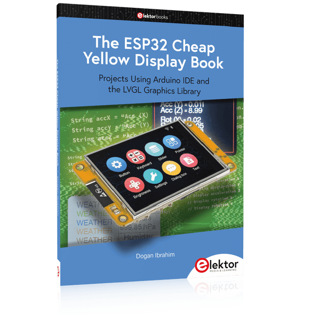
The ESP32 is probably one of the most popular microcontrollers used by many people, including students, hobbyists, and professional engineers. Its low cost, coupled with rich features makes it a popular device to use in many projects. Recently, a board called the ESP32 Cheap Yellow Display (CYD for short) is available from its manufacturers. The board includes a standard ESP32 microcontroller together with a 320x240 pixel TFT display. Additionally, the board provides several connectors for interfaces such as GPIO, serial port (TX/RX), power and Ground. The inclusion of a TFT display is a real advantage as it enables users to design complex graphics-based projects without resorting to an external LCD or graphics displays.
The book describes the basic hardware of the ESP32 CYD board and provides details of its on-board connectors. Many basic, simple, and intermediate-level projects are given in the book based on the ESP32 CYD, using the highly popular Arduino IDE 2.0 integrated development environment. The use of both the basic graphics functions and the use of the popular LVGL graphics library are discussed in the book and projects are given that use both types of approaches.
All the projects given in the book have been tested and are working. The block diagram, circuit diagram, and the complete program listings and program descriptions of all the projects are given with explanations. Readers can use the LVGL graphics library to design highly popular eye-catching full-color graphics projects using widgets such as buttons, labels, calendars, keypads, keyboards, message boxes, spinboxes, sliders, charts, tables, menus, bars, switches, drop-down lists, animations, and many more widgets.
NVIDIA JETSON NANO - BILDVERARBEITUNG FÜR EINSTEIGER (TEIL 2)Erkennen von Objekten mit Edge Impulse
ELEKTOR JUMPSTARTER-NEWSKommende Kampagnen
OPEN-SOURCE-GPS-TRACKING-PLATTFORMFahrzeug-Tracking ohne fremde Cloud mit Traccar
MULTIFUNKTIONS-KOMPONENTENTESTER LCR-T7 VON JOY-ITTesten von passiven Bauteilen, diskreten Halbleitern und IR-Fernbedienungen
RAUSCH-SYNTHESIZERVom Rauschen zur Musik mit dem PRBSynth1
ALLER ANFANG …ist gar nicht schwer! Weiter geht's mit der Spule...
DIE NEURONEN IN NEURONALEN NETZEN VERSTEHENTeil 2: Logische Neuronen
BLITZLICHT-GESCHÜTZTER ANALOGSPEICHER-ZUSATZ FÜR DAS MANIPULATIONSSICHERE DATENPAKETProbleme mit der Sicherheit? Bekämpfen Sie Feuer mit Feuer!
LCR METER POSTER
BLUETOOTH-BEACONS IN DER PRAXISOrtsbestimmung in Innenräumen
C-PROGRAMMIERUNG AUF RASPBERRY PIEin Beispielkapitel: Kommunizieren über WLAN
EMV-VORKONFORMITÄTSTEST FÜR IHR DC-VERSORGTES PROJEKTTeil 2: Die Hardware und wie man sie benutzt
PARALLAX PROPELLER 2Teil 5: Das Innenleben des Smart Pins
MODBUS ÜBER WLANTeil 1: Hardware und Programmierung
ZUTRITT FÜR UNBEFUGTE VERBOTENWie der Junior-Computer wieder zum Leben erweckt wurde
BAUEN SIE IHREN EIGENEN HOCHPRÄZISIONSKALIBRATOR-10 V bis +10 V, 0 bis 40 mA, 0,001%
ARDUINO NANO RP2040 CONNECTRaspberry Pi RP2040 + WLAN + Bluetooth
DER PHYSISCHE KÖRPER DER KÜNSTLICHEN INTELLIGENZ
PROJEKT 2.0Korrekturen, Updates und Leserbriefe
GRAFISCHE BENUTZEROBERFLÄCHEN MIT PYTHON UND GUIZERO
CO2-MESSGERÄT-SET FÜRS KLASSENZIMMEREin ESP8266-basiertes Gerät, entwickelt von der FH Aachen
NOSTALGISCHES MW/LW-RADIO MIT MK484...macht immer Spaß zu bauen!
60 JAHRE ELEKTOREs werde Licht!
HEXADOKUThe Original Elektorized Sudoku