
Search results for "raspberry OR pi OR 500 OR us"
-

Elektor Digital Das MQTT-Praxisbuch (PDF)
MQTT ist ein leichtgewichtiges, ereignis- und nachrichtenorientiertes Protokoll zur effizienten und asynchronen Kommunikation zwischen Geräten auch über limitierte Netzwerke. Das bereits 1999 von IBM entwickelte Protokoll eignet sich heute in besonderer Weise für Internet-of-Things-Anwendungen. Im Gegensatz zu HTTP mit Request/Response-Verfahren ist bei MQTT eine Publish/Subscribe-Architektur umgesetzt. Es stehen mittlerweile zahlreiche MQTT-Broker und -Clients zur Verfügung. Aufgrund der Unterstützung durch die Eclipse Foundation, IBM und vieler anderer stehen zahlreiche Komponenten kostenlos im Internet zur Verfügung. Client-Bibliotheken gibt es für die unterschiedlichsten Plattformen und Programmiersprachen. Unterstützt werden u. a. die PC-Plattform mit Java und .Net sowie Arduino und Raspberry Pi. Das MQTT-Praxisbuch führt Schritt für Schritt in die praktische Arbeit mit diesem ressourcensparenden Protokoll ein. Dabei widmet der Autor Walter Trojan dem Thema IoT-Sicherheit ein ausführliches Kapitel. Anhand von abgeschlossenen Projekten zum Nachbauen stellt der Autor in beeindruckender Weise die praktische Bedeutung des MQTT-Protokolls in modernen IoT-Anwendungen dar: MQTT auf ESP8266 MQTT mit Arduino-IDE MQTT-Benchmarks MQTT auf dem Raspberry Pi Flow-Programmierung mit Node-RED Boss aller Automaten: openHAB Projekt Gewächshaus mit automatisierter Beleuchtung, Bewässerung, Temperaturregelung sowie Luft- und Erdfeuchtigkeitsmessung
€ 32,80
Members: € 29,52
-

Elektor Juillet/Août 2025 (FR)
Le téléchargement intégral de ce numéro est disponible pour nos membres GOLD et GREEN sur le site Elektor Magazine ! Pas encore membre ? Cliquez ici. tableau de bord OBD2Des cadrans anciens aux données en temps réel OBD2 : ajoutez un compte-tours et un indicateur de changement de vitesse à votre voitureRétro, mais extrêmement utile capteurs de vision et LiDAR pour la robotique Sensor+Test 2025 et PCIM 2025 mesures sans contact du champ électrique (1)Membrane vibrante pour mesurer des tensions continues ou des champs électriques statiques détecteur de courrier sans filCapteurs optiques, radars… quelques options à explorer Elektor Mini-WheelieUn robot auto-équilibré cellules solairesDrôles de composants, la série premiers pas avec un capteur radar moderneUn capteur précis qui ne passe pas inaperçu sur le vifUsine de papier CybersécuritéDes temps difficiles pour les hackers Infographie : IdO et capteurs le Bluetooth 6.0 pour des applications de télémétrie amélioréesCette nouvelle version offre des fonctions de localisation améliorées découvrez la communication sans fil avec BeagleY-AI Projet 2.0Corrections, mises à jour et courrier des lecteurs démarrer en électronique……Conclusion sur les ampli-op un puissant assistant de codage de l'IAAccélérez votre développement avec Continue et Visual Studio Code contrôleur de charge solaire avec MPPT (2)Le circuit détecteur d'obstacles à ultrasonsUn projet simple pour aider les malvoyants une odyssée de l'IABilan du premier semestre synthétiseur MIDI autonome Raspberry Pi (3)plus intelligent avec une interface utilisateur Meshtastic : un projet de démoUn réseau intelligent de noeuds LoRa générateur analogique de fréquences audioGénérateur de signaux sinusoïdaux de haute qualité à fréquence réglable
€ 15,50
-

Elektor Digital Elektor March/April 2021 (PDF) EN
The Vision and Engineering Behind SparkFun Getting Started with MicroMod Leveling Up Your SparkFun JetBotHow I Expanded the Functionality of My JetBot, Powered by the NVIDIA Jetson Nano Programming an FPGA How to Build a DIY GNSS Reference Station The ClockClock Project Under the Hood: SparkFun Inventor's Kit SparkFun’s Glenn Samala on Product Development and New Ventures Creating Custom Circuit Boards with SparkFun À La Carte Designing with the SparkFun Artemis Getting Started with the Qwiic Ecosystem for Rapid Prototyping Poster - Qwiic Under the Hood: The GreatScott! / Elektor DIY LiPo Supercharger Kit Memorable Electronics from SparkFun Past Perfect Parking with LiDAR Buried Pad PCB Fixing Design to Sale: the SparkFun RTK Surveyor Hello World from the Raspberry Pi Pico and RP2040A Look at Raspberry Pi’s First Microcontroller and Microcontroller Chip DIY Quadrupedal Robots Poster - Micromod RISC-V IoT Development in AWS Using FreeRTOS Libraries Yep, Electronics = Fun!A Conversation Among Electronics Enthusiasts Sparkfun Product Catalog HexadokuThe Original Elektorized Sudoku
€ 7,50
-

Elektor Digital GSM/GPRS Projects (E-book)
Based on PIC microcontrollers and Arduino Every mobile phone includes a GSM/GPRS modem which enables the phone to communicate with the external world. With the help of the GSM modems, users can establish audio conversations and send and receive SMS text messages. In addition, the GPRS modem enables users to connect to the internet and to send and receive large files such as pictures and video over the internet. This book is aimed for the people who may want to learn how to use the GSM/GPRS modems in microcontroller based projects. Two types of popular microcontroller families are considered in the e-book: PIC microcontrollers, and the Arduino. The highly popular mid-performance PIC18F87J50 microcontroller is used in PIC based projects together with a GSM Click board. In addition, the SIM900 GSM/GPRS shield is used with the Arduino Uno projects. Both GSM and GPRS based projects are included in the e-book. The book will enable you to control equipment remotely by sending SMS messages from your mobile phone to the microcontroller, send the ambient temperature readings from the microcontroller to a mobile phone as SMS messages, use the GPRS commands to access the internet from a microcontroller, send temperature readings to the cloud using UDP and TCP protocols and so on. It is assumed that the reader has some basic working knowledge of the C language and the use of microcontrollers in simple projects. Although not necessary, knowledge of at least one member of the PIC microcontroller family and the Arduino Uno will be an advantage. It will also be useful if the user has some knowledge of basic electronics.
€ 24,95
Members: € 22,46
-

Elektor Digital Elektor Mai/Juin 2022 (PDF)
Vos premiers pas avec l?ESP32-C3 et l?IdOBouton Wi-Fi + relais Wi-Fi Cloud IdO à la sauce Arduino Détecteur Geiger-Müller à double tube (extension pour Arduino)Capteur très sensible pour très faible rayonnement Détecteur de CO2 : CO2 GuardUne solution « maison » pour surveiller la qualité de l'air Kit de mesure de la qualité de l?air pour Raspberry Pi de MonkMakesMesure de température et de CO2e Démarrer en électronique... (13)Entrée en scène de la diode Trucs et astuces pour tester les composantsSans appareils de test coûteux Réduction de la consommation d?énergie de votre repousse-taupesGrâce au remplacement du 555 par un ATtiny13 Interrupteur crépusculaire DeLuxUne solution pour une commutation de haute précision, commandée par la lumière Les défis de la commercialisation des solutions IdOProblématiques de sécurité, d'évolutivité et de concurrence Elektor infographieIoT : le nouveau Graal ? « Je préfère quand même être en filaire »Conseils pour développer une interface 1 Gbit/s dans un environnement industriel La détection d?objets en temps réel pour les microcontrôleurs grâce à Edge Impulse FOMO Tubes à ondes progressivesPeculiar Parts, the Series NB-IoTNormes, couvertures, conventions et modules Passerelle intérieure Dragino LPS8Configuration rapide de la passerelle LoRaWAN Explorer les microcontrôleurs ATtiny en utilisant le langage C et le langage assembleurExtrait : Ports d?E/S d?ATtiny Électronique interactive : projet 2.0Corrections, mises à jour et courriers des lecteurs Mise à jour de la balise GPS LoRaRecevoir et afficher la localisation à l?aide d?un Raspberry Pi Simulation de circuits avec TINA Design Suite & TINACloudExtrait : oscillateurs sinusoïdaux Sur le vifFaçon de pincer Infrastructure graphique WinUI pour les applications WindowsApplication de démonstration Création d?interfaces graphiques en Python avec guizeroLa pire des interfaces Systèmes solaires autonomesProduction d?électricité indépendante du réseau 10 ans avec le même smartphone ?Et si c?était possible ! Hexadoku
€ 10,95
-

JOY-iT JOY-iT PS1440-C-Pro Programmable Laboratory Power Supply with RS485 (1440 W)
With the JOY-iT PS1440-C-Pro, you get a programmable laboratory power supply that delivers DC voltages ranging from 0.01 to 60 V and DC currents from 0.01 to 24 A at the voltage output. The intuitive control panel allows you to program, store, and recall up to 9 different DC voltage settings. You can also configure individual protection and limiting functions—such as overvoltage protection. All settings are easily adjusted via the keypad and/or rotary control and are clearly shown on the high-resolution 2.4" color display. For enhanced connectivity, the PS1440-C-Pro includes an RS485 interface for robust, long-distance communication. This makes it ideal for complex setups where signal stability, noise immunity, and reliable data transfer are critical. The included connector ensures a secure connection, improving the overall reliability and performance of your laboratory equipment setup. Features Complete device ready for immediate use RS485 interface Battery charging function Values can be entered conveniently via keypad Over current & over voltage protection adjustable Integrated RTC, NTC temperature sensor Included detailed documentation in English, German & French Specifications Input voltage 230 V Output voltage 060 V Output current 0-24 A Output power 0-1440 W Input voltage accuracy ±1% +5 digits Output voltage accuracy ±0.3% +3 digits Output current accuracy ±0.5% +5 digits Battery voltage ±0.5% +3 digits Input voltage measurement resolution 0.01 V Output voltage measurement resolution 0.01 V Current measurement resolution 0.01 V Battery voltage measurement resolution 0.01 V Response time in constant voltage mode 2 ms @ 0.1-5 A Load regulation in constant voltage mode ±0.1% +2 digits Load regulation in constant current mode ±0.1% +3 digits Measuring range electric charge 0-9999.99 Ah Measuring range energy 0-9999.99 Wh Statistical errors in electric charge & energy ±2% Output ripple 100 mV VPP @ 12 V150 mV VPP @ 24 V Sensor temperature detection range −10~100°C (0-200°F) Sensor temperature detection accuracy ±3°C (±6°F) Working mode Step-down operation Screen brightness setting Level 0-5, 6 levels in total Permissible working temperature −10~40°C (0-104°F) Dimensions 170 x 93 x 340 mm Included JOY-iT PS1440-C Power Supply 2-pin connector for RS485 interface Power cord Manual Downloads Datasheet MODBUS Protocol PC Software Driver for Windows
€ 499,00
Members: € 449,10
-

Rigol Rigol DS1054Z 4-ch Oscilloscope (50 MHz)
Specifications Bandwidth: 50 MHz Analog Channels: 4 Real-time sample rate up to 1 GS/s Memory depth up to 24 Mpts Up to 30,000 wfms/s waveform capture rate Up to 60,000 frames hardware real-time waveform recording and playback functions Innovative 'UltraVision' technology Various trigger and bus decoding functions Low noise floor, vertical scale range: 1 mV/div to 10 V/div Various interfaces: USB Host&Device, LAN (LXI), AUX Compact size, light weight, easy to use 7 inch WVGA (800x480) TFT LCD, intensity graded color display Included 1x Rigol DS1054Z Oscilloscope 1x Power cord 1x USB cable 4x PVP2150 Passive oscilloscope probe (150 MHz)
€ 409,00
-

Elektor Digital Elektor 05-06/2023 PDF (DE)
Diese Ausgabe steht allen GOLD- und GREEN-Mitgliedern auf der ElektorMagazine-Website zum Download bereit! Sie sind noch kein Mitglied? Hier klicken! Super-Servo-TesterBis zu vier Servos einzeln oder eingebaut testen Analoge Signale und der MikrocontrollerADCs, DACs, Strommessung und mehr embedded world 2023 Sub-Nyquist-Sampling in der PraxisHöhere Frequenzen mittels Unterabtastung sicher erfassen Hier Android-Smartphone, dort ESP32?Praxisprojekt mit der Android WiFi-API Aktives 1-kHz-Filter für VerzerrungsmessungenBessere Messungen durch Optimierung des Messsignals Aller Anfang...muss nicht schwer sein: Wir multivibrieren weiter! Projekt 2.0Korrekturen, Updates und Leserbriefe Das neue I3C-ProtokollWürdiger I2C-Nachfolger oder viel Rauch um Nichts? BlueRC: IR-Fernsteuerung mit Smartphone und ESP32Anpassungsfähig und universell Mikrocontroller-Dokumentationen verstehenTeil 2: Register und Blockschaltbilder Automatisierung der Prüf- und MesstechnikProgrammieren von Prüfgeräten, damit sie tun, was Sie wollen Infografik: Messen und Testen Überspannungsschutz für sicheren BetriebTransientenschutz für nicht-isolierte DC/DC-Leistungsmodule Mess- und Prüfgeräte von WihaInstallationstester und Messgeräte, auf die Sie sich verlassen können Automatisierung von Tests und Zusammenarbeit bei Testergebnissen Aus dem Leben gegriffenElektronik auf hohem Niveau EnergieloggerEnergie messen und aufzeichnen Aufgebaut: Das 4tronix M.A.R.S. Rover Kit Parkscheibe mit E-Paper DisplayEin innovativer digitaler Ersatz eCO2-Telegram-BotLuftqualitätsmessung mit Telegram-Anbindung Hinter den Kulissen von High-End-Audio im EigenbauElektor-Ingenieur Ton Giesberts im Interview über die hohe Kunst des Analogdesigns Das besondere ProjektEs gibt noch viel zu tun! RFID-Tag lesen und RFID-TürschlossProjektbeispiele aus dem Arduino-Experimentierpaket von Elektor Oszilloskop-Stromsonde für HFHochfrequenz-Strommessung leichtgemacht Nichts für Anfänger – Makerfabs 6 DOF Robot ArmMit Raspberry Pi Pico und MicroPython Generative KIWer hat das eigentlich gemacht? Hexadoku
€ 11,90
-
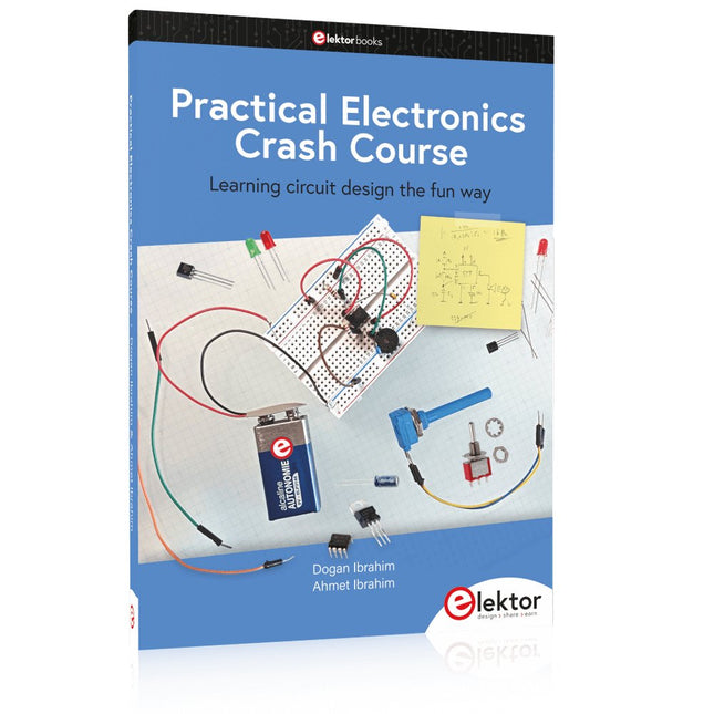
Elektor Publishing Practical Electronics Crash Course
Learning circuit design the fun way Welcome to the world of electronics! Getting started in electronics is not as difficult as you may think. Using this book, you will explore and learn the most important electrical and electronics engineering concepts in a fun way by doing various experiments and by simulating circuits. It will teach you electronics practically without getting into complex technical jargon and long calculations. As a result, you will be creating your own projects soon. No prior knowledge of electronics is required, only some basic algebra is used in a few simple calculations. Many tested and working projects and simulations are presented to familiarise yourself with the construction of electronic circuits. Circuit simulation is introduced at an early stage to enable you to experiment with circuits easily without breaking anything. You will learn: The concepts of voltage, current, and power AC and DC Basic lamp circuits with switches Passive components: resistors, capacitors & inductors RC & RCL circuits Electromagnetism Loudspeakers, relays, buzzers, and transformers Active components: diodes & LEDs, bipolar transistors & MOSFETs Transistor-based switching circuits Optocoupler circuits Astable & monostable multivibrators Using the 555 timer IC The operational amplifier Digital logic Advanced examples: amplifiers, oscillators, filters, and sensors Test and measurement tools Microcontrollers: Arduino UNO, ESP32, Raspberry Pi Pico, and Raspberry Pi Reading datasheets and best practices for selecting components EMC & EMI and norms & regulations
€ 39,95
Members: € 35,96
-
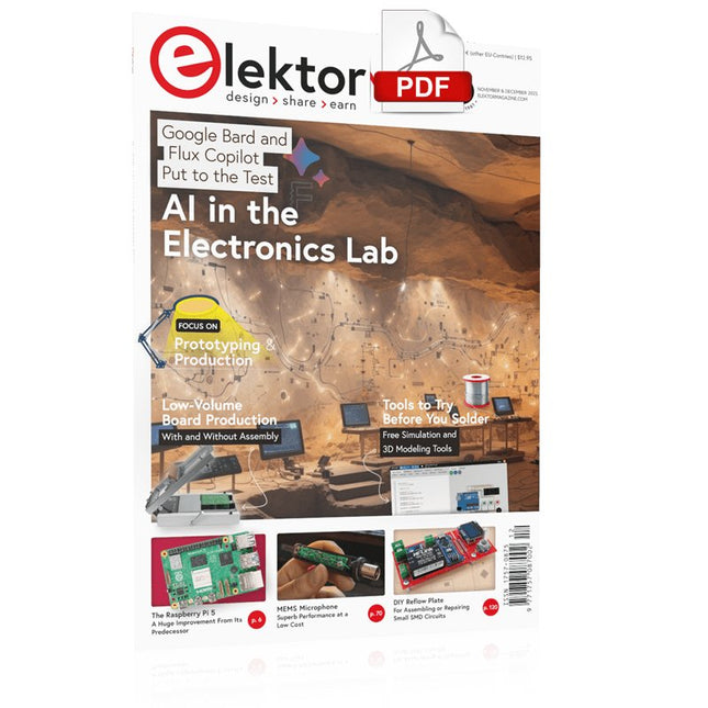
Elektor Digital Elektor November/December 2023 (PDF)
Elektor GREEN and GOLD members can download their digital edition here. Not a member yet? Click here. The Raspberry Pi 5A Huge Improvement From Its Predecessor AI in the Electronics LabGoogle Bard and Flux Copilot Put to the Test Arduino Nano Waveform GeneratorNano + Code = Function Generator Solar-Powered Christmas GarlandAn Eco-Friendly Solution for Garnishing Your Balcony USB Killer DetectorBetter Safe Than Sorry A Simple CNCed EnclosureWith Autodesk Fusion 360 for Personal Use Low-Volume Board ProductionWith and without Assembly IoT Simulation Simplified with WokwiDeveloper Uri Shaked on Design, Software, and More A Bare-Metal Programming Guide (Part 3)CMSIS Headers, Automatic Testing, and a Web Server LoRa, a Swiss Army Knife (2)The Hardware and Software MEMS Microphone Design and Construction Tools to Try Before You SolderSimulation and 3D Modeling Tools That Can Be Used for Free New Tools From Microchip!PICkit 5 and MPLAB ICD 5 Available Now! Rapid Prototyping of Flexible, Stretchable ElectronicsHow the Voltera NOVA Speeds Up Innovation in Wearable Electronic Systems Galvanic IsolationUsing Phototransistor Optocouplers Successfully The Complex Solution or the Anybus Solution?Embedded Industrial Ethernet in 2 Days Rather Than Many Months Your Essential DFM ChecklistHow to Start Designing for Manufacture 3D Printing FilamentsTypes, Features and Use in Prototyping Specialists for Effective Signal Analysis from ELF to EHF BandAaronia’s latest real-time SPECTRAN® V6 series spectrum analyzers Challenges of DFM Analysis for Flex and Rigid-Flex Design Setting Up an SMT Line The Right Combination for a Reliable Assembly Revolutionizing IndustriesThe Rise of Autonomous Mobile Robots (AMRs) Evolved for More ChallengesRohde & Schwarz Adds Eight-Channel R&S MXO 5 to Next-Generation Oscilloscopes Starting Out in Electronics……Amplifying Differences Mini Reflow PlateFor Assembling or Repairing Small SMD Circuits Don’t Start with a Prototype – Start with a Pretotype!Check That a Market Exists for Your Product Before Warming Your Soldering Iron 2023: An AI OdysseyGetting Help Designing a Physical Project Brussels Is InnovatingSupport for Deep Tech
€ 7,50
-
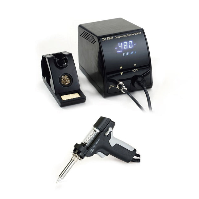
Zhongdi ZD-8965 Desoldering Station
The ZD-8965 is a digital temperature-controlled desoldering station equipped with ground protection and an LCD screen for temperature display. Despite its compact and robust design, this high-power desoldering station is easy to operate with just one hand. The ZD-8965 features a soldering gun with an integrated filter that captures any extracted material, allowing for continuous operation by simply replacing the filters. Additionally, a temperature sensor is embedded in the tip, enabling rapid response to temperature fluctuations for consistent performance. Features Effortlessly adjust the temperature between 160°C and 480°C using the convenient up/down buttons on the front panel. LED display to indicate the temperature in °C/°F Features an ergonomic pistol grip with a trigger for quick and efficient solder waste removal. The upgraded soldering gun includes a rear trigger, making it exceptionally convenient for replacing and cleaning components. Comes with a high-quality soldering gun and a sturdy holder. Equipped with a heavy-duty heater that ensures optimal desoldering performance every time. Specifications Station Voltage supply 220-240 V Power 140 W Vakuum pressure 600 mm HG Desoldering Gun Power 140 W (18 V DC)Heat up rating: 140 W Temperature 160-480°C (320-896°F) Heating element Ceramic heater Included 1x ZD-8965 Desoldering station 2x Spare soldering tips 3x Cleaning needles for desoldering tips 3x Spare filter for desoldering gun 1x Spare filter for desoldering station 1x Manual
€ 99,00
-

Elektor Labs Elektor Low-Noise Lab Power Supply
The Elektor Low-Noise Lab Power Supply is a fully analogue, adjustable, medium-power symmetrical bench supply that contains no switching or digital components. It provides an output voltage adjustable between 0 V and ±22 V, and an output current adjustable from 0 A to 1 A. Because it avoids any form of switching circuitry, the design delivers extremely low noise. To display both output voltages and currents, four miniature moving-coil panel meters are used. Most modern laboratory power supplies and AC adapters employ switch-mode techniques. Even the best examples inevitably exhibit high-frequency ripple and other switching artefacts on their output, which can interfere with the testing of sensitive analogue circuits and disturb low-level measurements. To overcome this, the concept here is a completely analogue power supply. Although less efficient than its switch-mode counterparts, the reduced efficiency is of little importance for test-bench use and ensures cleaner, more reliable measurement results. Because many analogue circuits require a symmetrical supply, this design delivers positive and negative output voltages of equal magnitude. A small amount of adjustment is available to compensate for any imbalance. Naturally, a variable current-limit function is also included. The kit includes the components required to build the power supply, except for the transformers. Specifications Output Voltage 0…+22 V, 0, −22 V Output Current 0…+1 A, 0…−1 A Noise −85 dBV, (at 0.95 A/20 V, B = 22 kHz) −84 dBV (at 0.95 A/20 V, B > 500 kHz) Ripple 50 µVRMS (at 950 mA/20 V, B = 22 kHz, mainly 100 Hz component) Included 3x PCBs: Regulator (PCB-1), Mains Filter (PCB-2) and Transformer (PCB-3) All the components except the AC transformers 4x moving-coil meters Additional parts for wiring (wires, banana sockets, IEC Power entry module, etc.) Not included The three AC transformers An enclosure Parts List For the Regulator PCB (240386-1) Resistors (250 mW, 1%) R1 = 12 Ω R2, R8, R37, R62 = 1 MΩ R3, R7, R10, R13, R17, R20, R22, R30, R35, R42, R45, R47, R55, R60 = 100 Ω, 600 mW R4, R5 = 4.7 kΩ R6 = 100 kΩ R9, R12, R14, R36, R38, R39, R61, R63, R66, R72, R78, R79 = 10.0 kΩ, 600 mW R11 = 9.76 kΩ, 600 mW R15, R40 = 44.2 kΩ, 600 mW R16, R41, R77 = 1 kΩ R18, R43 = 1.5 kΩ, 1 W, 5% R19, R44 = 470 Ω, 1 W, 5% R21, R46 = 330 Ω, 600 mW R23, R24, R48, R49 = 1.0 Ω, 1 W R25, R50 = 1 kΩ, 1 W, 5% R26, R28, R51, R53 = 1.000 kΩ 0.1%, 15 ppm/C R27, R29, R52, R54 = 10.00 kΩ 0.1%, 15 ppm/C R31, R56 = 1.2 kΩ, 1 W, 5% R32, R57 = 47 kΩ R33, R58 = 270 Ω R34, R59 = 27 kΩ R64, R69 = 12.0 kΩ R65 = 3.0 kΩ, 600 mW R67, R80 = 470 Ω, 600 mW R68, R70 = 6.8 kΩ, 600 mW R71 = 30.0 kΩ,, 600 mW R73, R74, R75, R76 = 10 MΩ P1, P2, P3 = 10 kΩ, 200 mW, 20%, potentiometer, 1 turns, single, lin., panel mount P4, P5 = 500 Ω, 500 mW, 10%, trimmer, 25 turns, 3296Y-1-501LF Bourns P6, P7 = 10 kΩ, 500 mW, 10%, trimmer, 25 turns, 3296Y-1-501LF Bourns Capacitors C1 = 100 nF, 50 V, 10%, ceramic X7R, LS 5 mm C2, C3, C6, C7, C30 = 10 µF, 63V, 20%, LS 2.5 mm, 3000hours@105°C C4, C5, C8, C9, C13, C14, C18, C19, C23, C24, C28, C29, C31, C32, C38, C39 = 100 nF, 250 V, 10%, PET, LS 7.5 mm C10, C20 = 47 nF, 100 V, 5%, PET, LS 5 mm C11, C21 = 10 nF, 100 V, 5%, PET, LS 5 mm C12, C22 = 220 µF, 35 V, 20%, 0.024 Ω, LS2.5/3.5 mm, Ir 3.4 A, 2000hours@125°C, polymer C15, C25 = 120 µF, 50 V, 20%, ESR 0.02 Ω, Diam. 10 mm max., LS 5 mm C16, C26 = 15 nF, 100 V, 5%, PET, LS 5 mm C17, C27 = 47 nF, 100 V, 5%, PET, LS 5 mm C33, C34 = 22 µF, 50 V, 20%, LS 2 mm, 10000 hours @ 105°C C35, C36, C44, C45 = 1 µF, 100 V, 10%, LS 5 mm, ceramic X7R C37 = 100 uF, 50 V, 20%. LS 3.5 mm C40, C41, C42, C43, C46, C47, C48, C49 = 1000 µF, 50 V, 20%, LS 5/7.5 mm, Ir 3.32 A, 10000hours@105°C, D 16 mm C50, C51, C52, C53 = 47 nF, 100 V, 10%, ceramic X7R, LS 5 mm Inductors L1, L2 = 4.7 µH, 3.2 A, 0.033 Ω, LS 5 mm, RLB0914-4R7ML Bourns L3 = Commom mode choke, 14.5 mH, 3 A, SSRH24NH-30145 Kemet Semiconductors D1, D2, D3, D4, D5, D9, D10, D11, D15 = BAT85, DO-34 D6, D7, D12, D13 = SR560, DO-201AD D8, D14, D16 = 1N4148, DO-35 D17 = Zenerdiode, 5.6 V, 0.5 W, DO-41 D18, D19 = 1N4004, DO-41 D20, D21 D22, D23 = V30100CI-M3/P, dual common cathode, TO-220 D24 = Zener diode, 30 V, 1 W, DO-41 LED1, LED2 = LED, red, T-1 (3 mm) LED3, LED4 = LED, green, T-1 (3 mm) TVS1, TVS2 = BZW50-33B, R6 T1, T2, T4 = BC337.25, TO-92 T3 = NJW0302G, TO-3P T5, T6, T8 = BC327.25, TO-92 T7 = NJW0281G, TO-3P T9 = BD139, TO-126 (SOT-32) IC1 = LM334Z, TO-92 IC2 = LM4040AIZ-5.0/NOPB, TO-92 (TO-226AA-3) IC3, IC4 = OPA2992IDR, SOIC-8 IC5, IC6 = OPA4992IDR, SOIC-14 IC7 = OPA992IDBVR, SOT-23-5 IC8 = LM339N, DIP-14 IC9 = LM317, TO-220 IC10 = LM337, TO-220 Others F1, F2 = 5×20 mm fuse, 1.6 A, fast acting HS1, HS2 = Heatsink MC33271 (for T3/T7), 2.7°C/W, PCB mount, height 63.5 mm K1, K4 = 3-way screw terminal block, LS 3.5 mm, max. 1.5 mm² K2, K3 = 3-way screw terminal block, LS 3.5 mm, max. 1 mm² M1, M3 = Moving coil meter, Range 30 V, type 91C4, 45×45 mm M2, M4 = Moving coil meter, Range 1 A, type 91C4, 45×45 mm² RE1 = Relay DPDT,5V, UA2-5NU Miscellaneous 3× 3-way screw terminal block, LS 3.5 mm, max. 1 mm² (for P1, P2, P3) 4× Pin header, 1×2, vertical, pitch 2.54 mm (for LED1, LED2, LED3, LED4) 4× Pin socket, 1×2, vertical. pitch 2.54 mm (for LED1, LED2, LED3, LED4) 2× Heatsink FK222SA220, 20°C/W, PCB mount (for IC9 & IC10) 2× Mica thermal pad for TO-220, 12×18×0.05 mm (for IC9 & IC10) 2× Insulating bushing IB 6, TO-220 (for IC9 & IC10) 2× Ceramic thermal pad, 23×20×2 mm (for T3 & T7) 2× PCB Fuse Holder, for 5×20 mm fuse, 10 A (for F1, F2) 2× Cover for PCB Fuse Holder, transparent (for F1, F2) 2× 2-way screw terminal block, LS 3.5 mm, max. 1 mm² (for M1 & M3) 2× 2-way screw terminal block, LS 3.5 mm, max. 1.5 mm² (for M2 & M4) 8× M3 solder lug, thickness 0.35 mm (for M1…M4) M4 solder lug, thickness 0.35 mm (to connect 4 mm banana connectors) Screened cable, 1 pair, 2×24 AWG/0.22 mm², 1 m (for P1, P2 & P3) IC socket, DIP, 14 contacts (for IC8) M3 washer, plain, steel M3 screw, 16 mm, steel, pan head M3 nut M3 spring washer 50 mm M3 standoff, steel, male-female 12 mm M3 standoff, steel, male-female 10 mm M3 standoff, steel, male-female M3 screw, 8 mm, steel, pan head For the Mains Fiter PCB (240386-2) Resistor R1 = 220 kΩ, 1 W, 500 V, 5% Capacitors C1, C2 = 470 nF, 305 VAC, Class X2, 11 × 27 mm max., LS 15/22.5 mm C3, C4, C5, C6 = 2.2 nF, 300 VAC, Class Y2, 13 × 4 mm, LS 10 mm, PP Inductors L1, L2 = Common-mode choke, 6.8 mH, 1.7 A, TDK B82732R2172B030 Semiconductor MOV1 = TVS varistor, 300 VAC, S14K300 (230 VAC, B72214S0301K101) and SK14K150 (150 VAC, B72214S0151K101) Others K1, K2 = 3-way screw terminal block, LS 7.62 mm F1 = Time-delay fuse, 0.5 A (230 VAC) or 1 A (115 VAC) Miscellaneous 1× Fuse holder, 5×20 mm, 10 A, 500 VAC 1× Transparent fuse cover 4× 10 mm M3 standoff, steel, male–female 4× M3 screw, 8 mm, steel, pan head 4× M3 nut For the Transformer PCB (240386-3) Resistors R1, R2 = 2.7 kΩ, 600 mW, 1% R3 = 10.0 kΩ, 600 mW, 1% Capacitor C1 = 220 µF, 50 V, 20%, Ø10 mm, LS 5 mm, 4000 h @ 105°C Transformers (not included in this kit!) TR1, TR2, TR3 = 2×7 V, 25 VA, PCB-mounted toroid, 70060K Talema Semiconductors D1–D4 = 1N4148, DO-35 D5, D6 = 1N4004, DO-41 D7 = Zener 5.6 V, 1.3 W, DO-41 LED1 = LED, red, T-1 (3 mm) IC1, IC2 = MOC8021M, CTR ≥ 1000%, DIP-6 Others F1, F2, F3 = 160 mA time-delay fuse (230 VAC) or 315 mA time-delay fuse (115 VAC) K1 = 2-way screw terminal block, LS 7.62 mm K2 = 3-way screw terminal block, LS 3.5 mm, max 1.5 mm² K3, K4 = 3-way screw terminal block, LS 3.5 mm, max 1 mm² RE1, RE2 = Relay DPDT, 5 A/250 VAC / 24 VDC Miscellaneaous 1× Pin header 1×2, pitch 2.54 mm + matching socket for LED1 3× Fuse holder 5 × 20 mm, 10 A, 500 VAC + transparent cover 3× M4 screw, 8 mm, pan head + washer for TR1-TR3 8× M3 screw, 8 mm, pan head + nut + washer 8× 10 mm M3 standoff, steel, male–female 2× IC socket, DIP-6 for IC1 & IC2 Additional Parts 1 m red insulated wire, stranded, 1.5 mm² 0.5 m blue insulated wire, stranded, 1.5 mm² 0.5 m black insulated wire, stranded, 1.5 mm², 0.5 m 2 m red insulated wire, stranded, D 0.56 mm (0.25 mm²) 2 m black insulated wire, stranded, D 0.56 mm (0.25 mm²) 0.5 m Multicore Cable, Flexible, 3 Core, 0.75 mm² (24 x 0.2 mm) Red banana socket Black banana socket Blue banana socket Green banana socket IEC Power Entry Module with switch, IEC C14 3 crimp terminals, FASTON, 4.75 x 0.81 mm 3 knobs Links Elektor Labs JumpStarter Page Article (Part 1) Article (Part 2)
€ 299,00€ 249,00Best Price


