
Search results for "building OR wireless OR sensor OR networks OR with OR openthread OR bundle"
-

Elektor Digital Electronic Security and Espionage (E-book)
A Handbook on DIY Nowadays, security problems are rarely properly solved or correctly addressed. Electronic security is only part of the chain in making a system secure. Electronic security is usually addressed as network or software security, neglecting other aspects, but the chain is only as strong as its weakest link. This book is about electronic hardware security, with an emphasis on problems that you can solve on a shoestring DIY budget. It deals mostly with secure communications, cryptosystems, and espionage. You will quickly appreciate that you can’t simply buy a trustworthy and reliable cryptosystem off the shelf. You will then realise that this applies equally to individuals, corporations, and governments. If you want to increase your electronic security awareness in a world already overcrowded with networks of microphones and cameras, this is a book for you. Furthermore, if you want to do something DIY by designing and expanding upon simple electronic systems, please continue reading. Some of the devices described are already published as projects in the Elektor magazine. Some are still ideas yet to be worked out. Complexity is the main enemy of security, so we'll try to keep to simple systems. Every chapter will analyse real-life espionage events or at least several hypothetical scenarios that will hopefully spark your imagination. The final goal is to build a security-conscious mindset (or “to get into a head of a spy”) which is necessary to recognise possible threats beforehand, to design a truly secure system. Don’t bother reading if: you think you and your secrets are 100% safe and secure you think somebody else can effectively handle your security you think conspiracy theories only exist in theory – Telefunken’s masterpiece the “FS-5000 Harpoon” was built on one!
€ 32,95
Members: € 29,66
-

Siglent Siglent SSA3032X Plus Spectrum Analyzer (9 kHz – 3.2 GHz)
The Siglent SSA3032X Plus spectrum analyzer is a powerful and flexible tool for RF signal and network analysis. With a frequency range of 3.2 GHz, the analyzer delivers reliable automatic measurements and multiple modes of operation: spectrum analyzer the base, optional functions include RF power measurement, vector signal modulation analysis, reflection measurement, and EMI test. Applications include broadcast monitoring/evaluation, site surveying, S-parameter measurement, analog/digital modulation analysis, EMI pre-compliance test, research and development, education, production, and maintenance. Features Spectrum Analyzer Frequency Range from 9 kHz to 3.2 GHz –161 dBm/Hz Displayed Average Noise Level (Typ.) –98 dBc/Hz. @ 10 kHz Offset Phase Noise (1 GHz, Typ.) Level Measurement Uncertainty <0.7 dB (Typ.) 1 Hz Minimum Resolution Bandwidth (RBW) Preamplifier (Std.) Tracking Generator (incl. free of charge) Analog and Digital Signal Modulation Analysis Mode (opt.) Reflection Measurement Kit (opt.) EMI Filter and Quasi-Peak Detector Kit (opt.) Advanced Measurement Kit (opt.) 10.1-inch Multi-Touch Screen , Mouse and Keyboard supported Web Browser Remote Control on PC and Mobile Terminals and File Operation Specifications SSA3015X Plus SSA3021X Plus SSA3032X Plus SSA3075X Plus Frequency Range 9 kHz ~ 1.5 GHz 9 kHz ~ 2.1 GHz 9 kHz ~ 3.2 GHz 9 kHz ~ 7.5 GHz Resolution Bandwidth 1 Hz ~ 1 MHz 1 Hz ~ 1 MHz 1 Hz ~ 1 MHz 1 Hz ~ 3 MHz Phase Noise <–99 dBc/Hz <–98 dBc/Hz <–98 dBc/Hz <–98 dBc/Hz Total Amplitude Accuracy <1.2 dB <0.7 dB <0.7 dB <0.7 dB Display Average Noise Level –156 dBm/Hz –161 dBm/Hz –161 dBm/Hz –165 dBm/Hz Included Siglent SSA3032X Plus spectrum analyzer USB cable Power cord Quick start guide Downloads Datasheet Manual Documentation Firmware
€ 2.951,19
-
Elektor Digital Elektor Special: Arduino Shields (PDF) EN
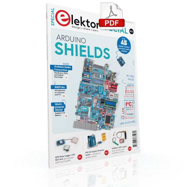
Make your project dreams come true: an odometer for the hamster wheel, a fully automatic control of your ant farm with web interface, or the Sandwich-O-Mat – a machine that toasts and grills sandwiches of your choice. With the Arduino and the DIY or Maker movement, not only did entry into microcontroller programming become child's play, but a second development also took place: Resourceful developers brought small boards – so-called shields or modules – to the market, which greatly simplified the use of additional hardware. The small modules contain all the important electronic parts to be connected to the microcontroller with a few plug-in cables, eliminating the need for a fiddly and time-consuming assembly on the plug-in board. In addition, it is also possible to handle tiny components that do not have any connecting legs (so-called SMDs). Projects Discussed Arduino seeks connection BMP and introduction to libraries, I²C Learn I/O basics with the multi-purpose shield I²C LCD adapter and DOT matrix displays LCD keypad shield Level converter W5100: Internet connection I/O expansion shield Relays and solid-state relays The multi-function shield: A universal control unit Connecting an SD card reader via SPI Keys and 7-segment displays 16-bit ADC MCP4725 DAC 16-way PWM servo driver MP3 player GPS data logger using an SD card Touch sensor Joystick SHT31: Temperature and humidity VEML6070 UV-A sensor VL53L0X time-of-flight Ultrasonic distance meter MAX7219-based LED DOT matrix display DS3231 RTC Port expander MCP23017 433 MHz radio MPU-650 gyroscope ADXL345 accelerometer WS2812 RGB LEDs Power supply MQ-xx gas sensors CO2 gas sensor ACS712 current sensor INA219 current sensor L298 motor driver MFRC522 RFID 28BYJ-48 stepper motor TMC2209 silent step stick X9C10x digital potentiometer ST7735 in a color TFT display e-Paper display Bluetooth Geiger counter SIM800L GSM module I²C multiplexer Controller Area Network
€ 11,95
Members: € 10,76
-

Elektor Digital CAN et CAN FD (E-book)
Tout sur les protocoles et leur mise en œuvre avec Arduino Initialement destiné aux véhicules routiers, le réseau CAN (« Controller Area Network ») et son successeur le réseau CAN FD (« Flexible Data ») ont vu leurs champs d’application s’élargir à de nouveaux domaines. L’industrie propose de nombreux modules microcontrôleurs dotés d’une interface CAN et/ou CAN FD. L’environnement de développement Arduino a démocratisé la programmation de ces modules et il existe des bibliothèques qui implémentent un pilote CAN et/ou un pilote CAN FD. La première partie dresse un rapide historique des réseaux CAN et CAN FD et expose la problématique des lignes de transmission en abordant succinctement leur théorie et présentant des résultats de simulation Spice. La deuxième partie est consacrée au réseau CAN, en détaillant successivement la fonction logique du réseau, les transcepteurs, les contrôleurs, la topologie la plus classique (le bus) et d’autres moins courantes, les répéteurs et les passerelles. Les aspects particuliers du protocole, tels que le bit stuffing, l’arbitrage, les trames d’erreur, la détection des erreurs sont exposés. La discussion de la fiabilité du protocole est illustrée par des exemples mettant en évidence ses faiblesses. La troisième partie présente le protocole CAN FD, ses deux variantes CAN FD ISO et CAN FD non ISO, leurs fiabilités, leurs faiblesses, mises en évidence par des exemples. Différents transcepteurs et contrôleurs CAN FD sont décrits. La quatrième partie est dédiée aux applications : comment utiliser les services d’un pilote, concevoir une messagerie, utiliser un analyseur logique. Deux exemples d’application terminent cette partie. Ce livre s’adresse aux amateurs et aux ingénieurs non spécialistes pour comprendre les possibilités qu’offre un réseau CAN et comment on le met en œuvre. Un enseignant trouvera des informations pour approfondir ses connaissances et pour concevoir des travaux pratiques. Une connaissance des microcontrôleurs, de leur programmation, de l’électronique numérique aidera à la lecture des schémas. La connaissance du langage C++ et du langage de simulation électronique Spice facilitera la compréhension des programmes qui sont décrits dans le livre. Tous les codes source sont disponibles sur le dépôt GitHub de l’auteur. Téléchargements GitHub
€ 34,95
Members: € 31,46
-

Elektor Digital Introduction to Electronic Filters (E-book)
Learn RC and RL Filters with Hands-On Circuits and Simulation Introduction to Electronic Filters is your comprehensive guide to understanding, designing, and applying first-order electronic filters using resistors, capacitors, and inductors. Whether you are a student, maker, or educator, this book demystifies the theory behind RC and RL filters and bridges the gap between concepts and real-world applications through simulation and experimentation. From the basics of frequency response and phase shift to hands-on breadboard builds and Python-based simulations, this book offers a deeply practical learning experience. You will learn to analyse filters using Bode plots and phasors, and explore applications in audio tone shaping, sensor signal conditioning, noise reduction, and power supply filtering. As you progress, you’ll build, measure, simulate, and tune filters using modern tools like CircuitLab, Python, and the Analog Discovery 3. Each chapter includes thoughtfully crafted activities that reinforce learning by doing – designing filters for specific tasks, simulating dynamic behaviour, and observing how theory translates into performance. Inside you’ll find: A clear introduction to the fundamentals of electronic filters Detailed explanations of RC and RL filters, cutoff frequency, and phase Guided activities using both simulation and hardware tools Real-life applications in audio, sensors, power supplies, and more A beginner-friendly primer on Python and algebra for electronics Whether you’re working through simulations or experimenting with real components on your workbench, this book will help you develop a solid understanding of electronic filters and their role in practical circuits.
€ 32,95
Members: € 29,66
-

Siglent Siglent SSA3015X Plus Spectrum Analyzer (9 kHz – 1.5 GHz)
The Siglent SSA3015X Plus spectrum analyzer is a powerful and flexible tool for RF signal and network analysis. With a frequency range of 1.5 GHz, the analyzer delivers reliable automatic measurements and multiple modes of operation: spectrum analyzer the base, optional functions include RF power measurement, vector signal modulation analysis, reflection measurement, and EMI test. Applications include broadcast monitoring/evaluation, site surveying, S-parameter measurement, analog/digital modulation analysis, EMI pre-compliance test, research and development, education, production, and maintenance. Features Spectrum Analyzer Frequency Range from 9 kHz to 1.5 GHz –156 dBm/Hz Displayed Average Noise Level (Typ.) –99 dBc/Hz. @ 10 kHz Offset Phase Noise (1 GHz, Typ.) Level Measurement Uncertainty <1.2 dB (Typ.) 1 Hz Minimum Resolution Bandwidth (RBW) Preamplifier (Std.) Tracking Generator (incl. free of charge) Analog and Digital Signal Modulation Analysis Mode (opt.) Reflection Measurement Kit (opt.) EMI Filter and Quasi-Peak Detector Kit (opt.) Advanced Measurement Kit (opt.) 10.1-inch Multi-Touch Screen , Mouse and Keyboard supported Web Browser Remote Control on PC and Mobile Terminals and File Operation Specifications SSA3015X Plus SSA3021X Plus SSA3032X Plus SSA3075X Plus Frequency Range 9 kHz ~ 1.5 GHz 9 kHz ~ 2.1 GHz 9 kHz ~ 3.2 GHz 9 kHz ~ 7.5 GHz Resolution Bandwidth 1 Hz ~ 1 MHz 1 Hz ~ 1 MHz 1 Hz ~ 1 MHz 1 Hz ~ 3 MHz Phase Noise <–99 dBc/Hz <–98 dBc/Hz <–98 dBc/Hz <–98 dBc/Hz Total Amplitude Accuracy <1.2 dB <0.7 dB <0.7 dB <0.7 dB Display Average Noise Level –156 dBm/Hz –161 dBm/Hz –161 dBm/Hz –165 dBm/Hz Included Siglent SSA3015X Plus spectrum analyzer USB cable Power cord Quick start guide Downloads Datasheet Manual Documentation Firmware
€ 1.402,39
-

Elektor Labs Elektor Low-Noise Lab Power Supply
The Elektor Low-Noise Lab Power Supply is a fully analogue, adjustable, medium-power symmetrical bench supply that contains no switching or digital components. It provides an output voltage adjustable between 0 V and ±22 V, and an output current adjustable from 0 A to 1 A. Because it avoids any form of switching circuitry, the design delivers extremely low noise. To display both output voltages and currents, four miniature moving-coil panel meters are used. Most modern laboratory power supplies and AC adapters employ switch-mode techniques. Even the best examples inevitably exhibit high-frequency ripple and other switching artefacts on their output, which can interfere with the testing of sensitive analogue circuits and disturb low-level measurements. To overcome this, the concept here is a completely analogue power supply. Although less efficient than its switch-mode counterparts, the reduced efficiency is of little importance for test-bench use and ensures cleaner, more reliable measurement results. Because many analogue circuits require a symmetrical supply, this design delivers positive and negative output voltages of equal magnitude. A small amount of adjustment is available to compensate for any imbalance. Naturally, a variable current-limit function is also included. The kit includes the components required to build the power supply, except for the transformers. Specifications Output Voltage 0…+22 V, 0, −22 V Output Current 0…+1 A, 0…−1 A Noise −85 dBV, (at 0.95 A/20 V, B = 22 kHz) −84 dBV (at 0.95 A/20 V, B > 500 kHz) Ripple 50 µVRMS (at 950 mA/20 V, B = 22 kHz, mainly 100 Hz component) Included 3x PCBs: Regulator (PCB-1), Mains Filter (PCB-2) and Transformer (PCB-3) All the components except the AC transformers 4x moving-coil meters Additional parts for wiring (wires, banana sockets, IEC Power entry module, etc.) Not included The three AC transformers An enclosure Parts List For the Regulator PCB (240386-1) Resistors (250 mW, 1%) R1 = 12 Ω R2, R8, R37, R62 = 1 MΩ R3, R7, R10, R13, R17, R20, R22, R30, R35, R42, R45, R47, R55, R60 = 100 Ω, 600 mW R4, R5 = 4.7 kΩ R6 = 100 kΩ R9, R12, R14, R36, R38, R39, R61, R63, R66, R72, R78, R79 = 10.0 kΩ, 600 mW R11 = 9.76 kΩ, 600 mW R15, R40 = 44.2 kΩ, 600 mW R16, R41, R77 = 1 kΩ R18, R43 = 1.5 kΩ, 1 W, 5% R19, R44 = 470 Ω, 1 W, 5% R21, R46 = 330 Ω, 600 mW R23, R24, R48, R49 = 1.0 Ω, 1 W R25, R50 = 1 kΩ, 1 W, 5% R26, R28, R51, R53 = 1.000 kΩ 0.1%, 15 ppm/C R27, R29, R52, R54 = 10.00 kΩ 0.1%, 15 ppm/C R31, R56 = 1.2 kΩ, 1 W, 5% R32, R57 = 47 kΩ R33, R58 = 270 Ω R34, R59 = 27 kΩ R64, R69 = 12.0 kΩ R65 = 3.0 kΩ, 600 mW R67, R80 = 470 Ω, 600 mW R68, R70 = 6.8 kΩ, 600 mW R71 = 30.0 kΩ,, 600 mW R73, R74, R75, R76 = 10 MΩ P1, P2, P3 = 10 kΩ, 200 mW, 20%, potentiometer, 1 turns, single, lin., panel mount P4, P5 = 500 Ω, 500 mW, 10%, trimmer, 25 turns, 3296Y-1-501LF Bourns P6, P7 = 10 kΩ, 500 mW, 10%, trimmer, 25 turns, 3296Y-1-501LF Bourns Capacitors C1 = 100 nF, 50 V, 10%, ceramic X7R, LS 5 mm C2, C3, C6, C7, C30 = 10 µF, 63V, 20%, LS 2.5 mm, 3000hours@105°C C4, C5, C8, C9, C13, C14, C18, C19, C23, C24, C28, C29, C31, C32, C38, C39 = 100 nF, 250 V, 10%, PET, LS 7.5 mm C10, C20 = 47 nF, 100 V, 5%, PET, LS 5 mm C11, C21 = 10 nF, 100 V, 5%, PET, LS 5 mm C12, C22 = 220 µF, 35 V, 20%, 0.024 Ω, LS2.5/3.5 mm, Ir 3.4 A, 2000hours@125°C, polymer C15, C25 = 120 µF, 50 V, 20%, ESR 0.02 Ω, Diam. 10 mm max., LS 5 mm C16, C26 = 15 nF, 100 V, 5%, PET, LS 5 mm C17, C27 = 47 nF, 100 V, 5%, PET, LS 5 mm C33, C34 = 22 µF, 50 V, 20%, LS 2 mm, 10000 hours @ 105°C C35, C36, C44, C45 = 1 µF, 100 V, 10%, LS 5 mm, ceramic X7R C37 = 100 uF, 50 V, 20%. LS 3.5 mm C40, C41, C42, C43, C46, C47, C48, C49 = 1000 µF, 50 V, 20%, LS 5/7.5 mm, Ir 3.32 A, 10000hours@105°C, D 16 mm C50, C51, C52, C53 = 47 nF, 100 V, 10%, ceramic X7R, LS 5 mm Inductors L1, L2 = 4.7 µH, 3.2 A, 0.033 Ω, LS 5 mm, RLB0914-4R7ML Bourns L3 = Commom mode choke, 14.5 mH, 3 A, SSRH24NH-30145 Kemet Semiconductors D1, D2, D3, D4, D5, D9, D10, D11, D15 = BAT85, DO-34 D6, D7, D12, D13 = SR560, DO-201AD D8, D14, D16 = 1N4148, DO-35 D17 = Zenerdiode, 5.6 V, 0.5 W, DO-41 D18, D19 = 1N4004, DO-41 D20, D21 D22, D23 = V30100CI-M3/P, dual common cathode, TO-220 D24 = Zener diode, 30 V, 1 W, DO-41 LED1, LED2 = LED, red, T-1 (3 mm) LED3, LED4 = LED, green, T-1 (3 mm) TVS1, TVS2 = BZW50-33B, R6 T1, T2, T4 = BC337.25, TO-92 T3 = NJW0302G, TO-3P T5, T6, T8 = BC327.25, TO-92 T7 = NJW0281G, TO-3P T9 = BD139, TO-126 (SOT-32) IC1 = LM334Z, TO-92 IC2 = LM4040AIZ-5.0/NOPB, TO-92 (TO-226AA-3) IC3, IC4 = OPA2992IDR, SOIC-8 IC5, IC6 = OPA4992IDR, SOIC-14 IC7 = OPA992IDBVR, SOT-23-5 IC8 = LM339N, DIP-14 IC9 = LM317, TO-220 IC10 = LM337, TO-220 Others F1, F2 = 5×20 mm fuse, 1.6 A, fast acting HS1, HS2 = Heatsink MC33271 (for T3/T7), 2.7°C/W, PCB mount, height 63.5 mm K1, K4 = 3-way screw terminal block, LS 3.5 mm, max. 1.5 mm² K2, K3 = 3-way screw terminal block, LS 3.5 mm, max. 1 mm² M1, M3 = Moving coil meter, Range 30 V, type 91C4, 45×45 mm M2, M4 = Moving coil meter, Range 1 A, type 91C4, 45×45 mm² RE1 = Relay DPDT,5V, UA2-5NU Miscellaneous 3× 3-way screw terminal block, LS 3.5 mm, max. 1 mm² (for P1, P2, P3) 4× Pin header, 1×2, vertical, pitch 2.54 mm (for LED1, LED2, LED3, LED4) 4× Pin socket, 1×2, vertical. pitch 2.54 mm (for LED1, LED2, LED3, LED4) 2× Heatsink FK222SA220, 20°C/W, PCB mount (for IC9 & IC10) 2× Mica thermal pad for TO-220, 12×18×0.05 mm (for IC9 & IC10) 2× Insulating bushing IB 6, TO-220 (for IC9 & IC10) 2× Ceramic thermal pad, 23×20×2 mm (for T3 & T7) 2× PCB Fuse Holder, for 5×20 mm fuse, 10 A (for F1, F2) 2× Cover for PCB Fuse Holder, transparent (for F1, F2) 2× 2-way screw terminal block, LS 3.5 mm, max. 1 mm² (for M1 & M3) 2× 2-way screw terminal block, LS 3.5 mm, max. 1.5 mm² (for M2 & M4) 8× M3 solder lug, thickness 0.35 mm (for M1…M4) M4 solder lug, thickness 0.35 mm (to connect 4 mm banana connectors) Screened cable, 1 pair, 2×24 AWG/0.22 mm², 1 m (for P1, P2 & P3) IC socket, DIP, 14 contacts (for IC8) M3 washer, plain, steel M3 screw, 16 mm, steel, pan head M3 nut M3 spring washer 50 mm M3 standoff, steel, male-female 12 mm M3 standoff, steel, male-female 10 mm M3 standoff, steel, male-female M3 screw, 8 mm, steel, pan head For the Mains Fiter PCB (240386-2) Resistor R1 = 220 kΩ, 1 W, 500 V, 5% Capacitors C1, C2 = 470 nF, 305 VAC, Class X2, 11 × 27 mm max., LS 15/22.5 mm C3, C4, C5, C6 = 2.2 nF, 300 VAC, Class Y2, 13 × 4 mm, LS 10 mm, PP Inductors L1, L2 = Common-mode choke, 6.8 mH, 1.7 A, TDK B82732R2172B030 Semiconductor MOV1 = TVS varistor, 300 VAC, S14K300 (230 VAC, B72214S0301K101) and SK14K150 (150 VAC, B72214S0151K101) Others K1, K2 = 3-way screw terminal block, LS 7.62 mm F1 = Time-delay fuse, 0.5 A (230 VAC) or 1 A (115 VAC) Miscellaneous 1× Fuse holder, 5×20 mm, 10 A, 500 VAC 1× Transparent fuse cover 4× 10 mm M3 standoff, steel, male–female 4× M3 screw, 8 mm, steel, pan head 4× M3 nut For the Transformer PCB (240386-3) Resistors R1, R2 = 2.7 kΩ, 600 mW, 1% R3 = 10.0 kΩ, 600 mW, 1% Capacitor C1 = 220 µF, 50 V, 20%, Ø10 mm, LS 5 mm, 4000 h @ 105°C Transformers (not included in this kit!) TR1, TR2, TR3 = 2×7 V, 25 VA, PCB-mounted toroid, 70060K Talema Semiconductors D1–D4 = 1N4148, DO-35 D5, D6 = 1N4004, DO-41 D7 = Zener 5.6 V, 1.3 W, DO-41 LED1 = LED, red, T-1 (3 mm) IC1, IC2 = MOC8021M, CTR ≥ 1000%, DIP-6 Others F1, F2, F3 = 160 mA time-delay fuse (230 VAC) or 315 mA time-delay fuse (115 VAC) K1 = 2-way screw terminal block, LS 7.62 mm K2 = 3-way screw terminal block, LS 3.5 mm, max 1.5 mm² K3, K4 = 3-way screw terminal block, LS 3.5 mm, max 1 mm² RE1, RE2 = Relay DPDT, 5 A/250 VAC / 24 VDC Miscellaneaous 1× Pin header 1×2, pitch 2.54 mm + matching socket for LED1 3× Fuse holder 5 × 20 mm, 10 A, 500 VAC + transparent cover 3× M4 screw, 8 mm, pan head + washer for TR1-TR3 8× M3 screw, 8 mm, pan head + nut + washer 8× 10 mm M3 standoff, steel, male–female 2× IC socket, DIP-6 for IC1 & IC2 Additional Parts 1 m red insulated wire, stranded, 1.5 mm² 0.5 m blue insulated wire, stranded, 1.5 mm² 0.5 m black insulated wire, stranded, 1.5 mm², 0.5 m 2 m red insulated wire, stranded, D 0.56 mm (0.25 mm²) 2 m black insulated wire, stranded, D 0.56 mm (0.25 mm²) 0.5 m Multicore Cable, Flexible, 3 Core, 0.75 mm² (24 x 0.2 mm) Red banana socket Black banana socket Blue banana socket Green banana socket IEC Power Entry Module with switch, IEC C14 3 crimp terminals, FASTON, 4.75 x 0.81 mm 3 knobs Links Elektor Labs JumpStarter Page Article (Part 1) Article (Part 2)
€ 249,00
Best Price
-

Elektor Circuit Special 2026 (NL)
Elektor GREEN en GOLD leden kunnen deze uitgave hier downloaden. Nog geen lid? Klik hier om een lidmaatschap af te sluiten. Een stroombron voor het testen van Z-diodesControle van Z-diodes van 1 tot 54 V bij 1 tot 50 mA ESD polsbandtesterEen testapparaat met indicatie voor ‘goed’, ‘grensgeval’ en ‘afgekeurd’ Testapparaat voor de respons op piekbelastingen van voedingenEen generator voor repeterende stapsgewijze belasting voor laboratoriumvoedingen Euclidische sequencer zonder microcontrollerTriggerpatronen en CV-sequenties met eenvoudige CMOS-logica LED-knipperlicht voor heksystemen en meer, inclusief geluidssignaal Printen nodig? De Elektor PCB-service staat voor u klaar Tandenborstel-timerMet een kleine PIC Een contactloos magnetisch combinatieslotMet de AS5600 rotatie-positie sensor Batterijgevoede ruisarme voorversterkervoor dynamische microfoons Het Arduino Nano testLabMeten, sturen en regelen Rhythmische basverlichtingBenadruk het ritme van je muziek Low-cut filterGeen risico op audio-terugkoppeling op uw systeem Nauwkeurige 1 Hz blokgolfgenerator voor breadboardsEen betrouwbare klokpuls op basis van CMOS 555 onderstebovenDutycycles tot nul Van Halfgeleidergids tot Circuit Specials65 jaar innovatie op het gebied van elektronica Elektrische isolatieCAN-interface met digitale isolator en voedingsmodule SpongillatorEen sponsgebaseerde oscillator Echte willekeurige getallengeneratorMet geïntegreerde chi-kwadraattoets 3D-viewer voor HTML-pagina'sEenvoudig en vrijwel zonder code Programmeren met TLScriptEen scripttaal voor metingen, tests en besturing Schakelingsontwerp: tips van experts FeedbackWat is het en waarom is het belangrijk? Eén board, eindeloze ideeën: Arduino UNO QVan retro-gaming tot realtime milieumonitoring Hoe u een donut-antenne repareert Standby-KillerEen echte aan/uit-schakelaar voor uw tv Batterijen testenBatterijen meten met de Arduino Nano Voeding voor audioversterkersEen goede voeding zonder netbrom HF prototype printplatenMaak zelf snel een prototype printplaat Type 3-overspanningsbeveiligingEen type 3-overspanningsbeveiliging voor uw gevoelige apparatuur IoT-kamerthermostaat boardMet een op ESP32-C3/S3 gebaseerde Xiao MCU-module Van star naar slimFlexibele en gedrukte elektronica, tussen visie en industriële realiteit
€ 15,95
-

Elektor Digital Elektor Circuit Special 2026 (PDF) EN
Elektor GREEN and GOLD members can download their digital edition here. Not a member yet? Click here. A Current Source for Testing (Z-)DiodesChecking Z-Diodes from 1 to 54 V @ 1 to 50 mA ESD Strap TesterA Bench Tool with Pass, Borderline, and Fail Indication Power Supply Transient Response TesterA Repeatable Step-Load Generator for Bench Power Supplies Euclidean Sequencer Without a MicrocontrollerTrigger Patterns and CV Sequences with Simple CMOS Logic LED Flashing Light for Gates and More with an Audible Alert Need PCBs? The Elektor PCB Service Has You Covered. Toothbrush TimerUsing a Tiny PIC A Contactless Magnetic Combination LockWith the AS5600 Rotary Position Sensor Low-Noise Battery-Powered PreamplifierFor Dynamic Microphones The Arduino Nano TestLabMeasurement, Control, and Regulation Rhythmic Bass LightEmphasize the Rhythm of Your Music Low-Cut FilterNo Risk of Audio Feedback on Your System Precise 1 Hz Square Wave Generator for BreadboardsA Reliable CMOS-Based Clock Source 555 Upside DownDuty Cycles Down to Zero From Halfgeleidergids to Circuit Specials65 Years of Electronics Innovation Electrical IsolationCAN Interface with Digital Isolator and Power Module SpongillatorA Sponge-Based Oscillator True Random Number GeneratorWith Integrated Chi-Square Test 3D Viewer for HTML pagesSimple, and Almost Without Code Programming with TLScriptA Scripting Language for Measurement, Testing, and Control Circuit Design: Tips from Experts FeedbackWhat Is It and Why Is It Important? One Board, Endless Ideas: Arduino UNO QFrom Retro Gaming to Real-Time Environmental Monitoring How to Fix a Donut Antenna Standby KillerA Real On/Off Switch for Your TV Battery TestingMeasuring Batteries with the Arduino Nano Power Supply for Audio Power AmplifiersA Good Power Supply Without Mains Hum Prototyping Boards for RFFast Setups with DIY Prototyping Boards T3 Surge ProtectionA Type 3 Spike Suppressor for Your Sensitive Equipment IoT Room Thermostat BoardWith ESP32-C3/S3-Based Xiao MCU module From Rigid to SmartFlexible and Printed Electronics — Between Vision and Industrial Reality
€ 9,50
-
Elektor Digital The Bottle Builder (E-book)
The author, Johan Basse Bergqvist, is an engineer, a musician, and an audiophile with a knack for building projects that produce the desired results. The combination of these skills leads to a uniquely valuable perspective on audio design that is routinely reflected in the book and passed on to the readers. Several design projects are provided, 40 in total. The designs are explained, and the unique features or methods he uses are described in further detail. Each design includes detailed schematics and a complete parts list. Many of the projects also include layout documentation in the form of CAD photos of the PCB layouts. The range of projects is very diverse and includes something that will appeal to everyone. Stereo amplifiers, guitar and bass amplifiers, preamplifiers for phono, and microphones are all covered. Several variants for each type are included, and the power amplifier designs range from a few watts to several hundred watts, which meet almost any power level you might tackle.
€ 64,95
Members: € 58,46
-

Elektor Publishing Autonomous Robotics from the Ground Up
The Black Shadow Project: From Sensors to Embedded AI Most robotics books stop at individual components or jump to frameworks that hide the hardware. This book explores how a complete autonomous robot is designed, integrated and debugged from first principles, following an engineer’s practical problems, failed approaches and workable solutions. Three dedicated dual-core microcontrollers divide perception, motor control and navigation, reducing timing conflicts. Sixteen time-of-flight sensors across eight independent I²C buses provide 360° environmental coverage at 20 Hz. Their measurements feed a trained neural network that performs real-time obstacle avoidance directly on the microcontroller using TensorFlow Lite for Microcontrollers, without cloud services or a GPU. A built-in Wi-Fi access point and browser interface give your smartphone access to live telemetry, sensor visualisation and manual driving without installing an app. An onboard virtual machine executes bytecode scripts one instruction per scheduler tick, allowing multi-step manoeuvres without blocking real-time control loops. This establishes a foundation for increasingly independent behaviour. The closing chapter examines what separates shared control from the book’s goal of Level 3 autonomy: self-localisation, mission planning, reliable heading, predictive power management and recognising when to stop. It outlines possible solutions, then challenges you to design Black Shadow 2.0. Throughout, the emphasis remains on integration, troubleshooting and practical engineering decisions.
€ 39,95
Members: € 35,96
-

Elektor Digital Elektor November/December 2026 (PDF) NL
Elektor GREEN en GOLD leden kunnen deze uitgave hier downloaden. Nog geen lid? Klik hier om een lidmaatschap af te sluiten. AI-tools voor hardwareprototypingWat helpt, wat niet, en waar de technicus nog steeds nodig is ZSWatch, van idee tot productDeel 1: Een volledig open smartwatch Drieweg toonregelingHigh-end, voor net dat beetje extra electronica Fast Forward 202610 jaar innovatie Microcontroller prototypingEen overzicht van populaire boards Prototype-breadboardsVreemde onderdelen, de serie Ontwerpen voor de ruimteEen makers-gids voor COTS-selectie, stralingsbestendigheid en missie-architectuur Thermisch beheer voor betrouwbare elektronicaWanneer elke graad telt Van concept naar gadgetHet ontwikkelen van embedded systemen die daadwerkelijk op de markt worden gebracht EMI-ferriet voor DCF77-antennesEen alternatief voor traditionele ferriet-antennekernen Een robotarm leren zien en bewegenAI-gestuurde manipulatie met een 3D-geprinte robotarm Elektor op 65-jarige leeftijdProjecten uit november en december van vroeger Lusantenne met RF-bouwstenenDeel 2: Signaalverwerking Van prototype tot productiePraktische lessen van de Elektor-community Project updatesFeedback, ideeën, correcties Draagbare audiogeneratorEen referentiesignaalbron voor een snelle installatie van audiosystemen AudiotronicaMeer vervorming en een versterker met niveauaanpassing 2026: Een AI-odysseeWanneer AI begint met het bouwen van AI Wireless Workshop (2)Radio Modules Ontsluierd: 2,4 GHz nRF24L01P Transceiver Het digitale pad De Ontwikkeling van een Open-Source SmartwatchDaniel Kampert over ZSWatch, Open Hardware en Engineering Trade-offs Hoe u zich voorbereidt op professionele SMD-assemblage Engineering weg van de WerkbankSysteemintegratie, probleemoplossing en praktijktesten Avionica instrument simulatorOp basis van de ESP32-S3, met rond HMI-scherm
€ 9,95


