
Search results for "arduino or uno or experimenting or bundle"
-

Elektor Digital Raspberry Pi Pico W en un tournemain (PDF)
Maîtrise de la puce RP2040 avec plus de 60 projets à réaliser et à programmer Les cartes Raspberry Pi Pico et Pico W sont animées par un microcontrôleur ARM Cortex M0+ RP2040 à double coeur, rapide, efficace et peu coûteux, qui fonctionne jusqu'à 133 MHz et dispose de 264 Ko de SRAM et de 2 Mo de mémoire Flash. Outre une vaste mémoire, le Pico et le Pico W disposent de nombreuses broches GPIO et d'interfaces telles que CA/N, SPI, I²C, UART, MLI, de fonctions de temporisation, d'une interface de débogage matériel et d'un capteur de température interne. La carte Raspberry Pi Pico W comporte en plus une puce CYW43439 Bluetooth et Wi-Fi d'Infineon. Au moment de la rédaction de ce livre, le micrologiciel Bluetooth pour le Pico W n'était pas encore disponible. Le Wi-Fi à 2,4 GHz est toutefois entièrement pris en charge avec les protocoles 802.11b/g/n. Ce livre est une introduction à l'utilisation du Raspberry Pi Pico W avec le langage de programmation MicroPython. Les quelque soixante projets testés et opérationnels sont présentés à l'aide de l'environnement de développement intégré (EDI) Thonny. Les sujets abordés sont nombreux : Installation de MicroPython sur le Raspberry Pi Pico depuis un PC Interruptions de l'horloge et interruptions externes Convertisseur analogique-numérique (CA/N) Capteurs de température interne et externe Capteurs externes (pression, humidité, pouls, à ultrasons) Enregistrement de données MLI, UART, I²C et SPI Bluetooth, Wi-Fi et applis sur smarphone Convertisseur numérique-analogique (CN/A) Tous les projets ont été testés et éprouvés. Ils peuvent être mis en oeuvre sur le Raspberry Pi Pico ainsi que sur le Raspberry Pi Pico W. Toutefois les projets avec une liaison Wi-Fi ne fonctionnent que sur le Pico W. Une petite expérience en programmation et en électronique est nécessaire pour suivre les projets. De brèves descriptions, des schémas fonctionnels, des schémas détaillés du câblage des montages et des listings MicroPython complets sont fournis pour tous les projets.
€ 34,95
Members: € 31,46
-
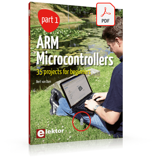
Elektor Digital ARM Microcontrollers (EN) | E-book
35 Projects for Beginners This book is for hobbyists, students and engineers who want to learn C and how to use an mbed ARM microcontroller in an easy and fun way, without the need for cumbersome software installations. ARM mbed microcontroller NXP LPC1768 The projects in this book are meant for beginners in C and ARM microcontrollers. That doesn't mean the projects are simple, but it does mean that they are easy to understand. We use for example USB communications, a subject that is made so easy by the mbed that it is suitable for a beginners book. Cloud technology The mbed NXP LPC1768 uses cloud technology, a revolutionary concept in software development. This means you do not need to install software on your PC in order to program the mbed! The only thing you need is a browser such as Microsoft Internet Explorer, and a USB port on your PC. You can get access to your project from any PC anywhere in the world and continue working on it. When you are done a few simple mouse clicks transfer the program to your mbed hardware. Of course you can optionally download the projects and store them on your own PC. Features of this Book Learn how to program an mbed ARM microcontroller using cloud technology. No complicated software installation on your PC needed. Learn programming in C by doing fun and interesting projects. No previous experience or knowledge required. Examples of projects in this book: flashing light, timer, light activated switch, digital thermometer, people detector, USB communication, talking microcontroller, debugging, sound switch, and much more - 35 projects in total. Examples of C subjects in this book: variables, commands, functions, program execution, pointers (introduction).
€ 29,95
Members: € 26,96
-

Elektor Digital Elektor Septembre/Octobre 2026 (PDF) FR
Le téléchargement intégral de ce numéro est disponible pour nos membres GOLD et GREEN sur le site Elektor Magazine ! Pas encore membre ? Cliquez ici. l'ESP-BLASTUn mini drone-fusée ESP32 qui vole à plus de 100 km/h atelier sans fil (1)Modules radio déverrouillés : émetteur-récepteur sub-GHz CC1101 433 MHz émetteur AMAvec le générateur d'ondes carrées/sinusoïdales sur Raspberry Pi Pico STM32Cube Innovation ChallengeParticipez avec votre meilleur projet STM32C5 CoffeeCallerComment une pause café a inspiré un PCB sur mesure audiotroniquesDistorsion harmonique totale Elektor à 65 ansProjets de septembre et octobre au fil des ans Bluetooth Channel Sounding pour le suivi des équipementsMesure de distance avec une précision centimétrique pour l’IoT de nouvelle génération 2026 : une Odyssée de l'IAL'informatique quantique n'est pas le prochain GPU protéger le cloud exige de sécuriser la périphérie premières expériences avec le HackRF ProTests pratiques avec le nouveau matériel SDR mise à niveau du modem de GPRS/2G vers LTE/4GExemple d'un panneau de contrôle d'alarme sans fil antenne en bouclePartie 1 : Une antenne ondes courtes à directivité réglable, à réaliser soi-même convertisseur de radio Internet en AMUn ESP32-S3 comme émetteur projet 2.0 mioty : aperçu généralL'approche de Fraunhofer pour les LPWAN sagesse d'atelierConseils pratiques d'experts Walter, le module IoT compactPartie 2 : Accéder aux services météorologiques et aux services de données
€ 10,95
-
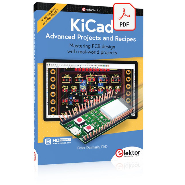
Elektor Digital KiCad Like A Pro – Advanced Projects and Recipes (E-book)
Mastering PCB design with real-world projects This book builts on KiCad Like a Pro – Fundamentals and Projects and aims to help you practice your new KiCad skills by challenging you in a series of real-world projects. The projects are supported by a comprehensive set of recipes with detailed instructions on how to achieve a variety of simple and complex tasks. Design the PCBs for a solar power supply, an LED matrix array, an Arduino-powered datalogger, and a custom ESP32 board. Understand the finer details of the interactive router, how to manage KiCad project teams with Git, how to use an autorouter on 2 and 4-layer PCBs, and much more. KiCad 8 is a modern, cross-platform application suite built around schematic and design editors. This stable and mature PCB tool is a perfect fit for electronic engineers and makers. With KiCad 8, you can create PCBs of any complexity and size without the constraints associated with the commercial packages. Here are the most significant improvements and features in KiCad 8, both over and under the hood: Modern user interface, completely redesigned from earlier versions Improved and customizable electrical and design rule checkers Theme editor allowing you to fully customize the look of KiCad on your screen Ability to import projects from Eagle, CADSTART, and more An improved and tightly integrated SPICE circuit simulator Autorouting with the Freerouting plugin Filters define which elements of a layout are selectable Enhanced interactive router helps you draw single tracks and differential pairs with precision New or enhanced tools to draw tracks, measure distances, tune track lengths, etc. Enhanced tool for creating filled zones A customizable coordinate system facilitates data exchange with other CAD applications Realistic ray-tracing capable 3D viewer Differential pair routing Rich repositories of symbol, footprint, and 3D shape libraries Python scripting API for programmatic customization and extensions Improved footprint wizard for fast custom footprints
€ 39,95
Members: € 35,96
-

Elektor Labs Elektor Low-Noise Lab Power Supply
The Elektor Low-Noise Lab Power Supply is a fully analogue, adjustable, medium-power symmetrical bench supply that contains no switching or digital components. It provides an output voltage adjustable between 0 V and ±22 V, and an output current adjustable from 0 A to 1 A. Because it avoids any form of switching circuitry, the design delivers extremely low noise. To display both output voltages and currents, four miniature moving-coil panel meters are used. Most modern laboratory power supplies and AC adapters employ switch-mode techniques. Even the best examples inevitably exhibit high-frequency ripple and other switching artefacts on their output, which can interfere with the testing of sensitive analogue circuits and disturb low-level measurements. To overcome this, the concept here is a completely analogue power supply. Although less efficient than its switch-mode counterparts, the reduced efficiency is of little importance for test-bench use and ensures cleaner, more reliable measurement results. Because many analogue circuits require a symmetrical supply, this design delivers positive and negative output voltages of equal magnitude. A small amount of adjustment is available to compensate for any imbalance. Naturally, a variable current-limit function is also included. The kit includes the components required to build the power supply, except for the transformers. Specifications Output Voltage 0…+22 V, 0, −22 V Output Current 0…+1 A, 0…−1 A Noise −85 dBV, (at 0.95 A/20 V, B = 22 kHz) −84 dBV (at 0.95 A/20 V, B > 500 kHz) Ripple 50 µVRMS (at 950 mA/20 V, B = 22 kHz, mainly 100 Hz component) Included 3x PCBs: Regulator (PCB-1), Mains Filter (PCB-2) and Transformer (PCB-3) All the components except the AC transformers 4x moving-coil meters Additional parts for wiring (wires, banana sockets, IEC Power entry module, etc.) Not included The three AC transformers An enclosure Parts List For the Regulator PCB (240386-1) Resistors (250 mW, 1%) R1 = 12 Ω R2, R8, R37, R62 = 1 MΩ R3, R7, R10, R13, R17, R20, R22, R30, R35, R42, R45, R47, R55, R60 = 100 Ω, 600 mW R4, R5 = 4.7 kΩ R6 = 100 kΩ R9, R12, R14, R36, R38, R39, R61, R63, R66, R72, R78, R79 = 10.0 kΩ, 600 mW R11 = 9.76 kΩ, 600 mW R15, R40 = 44.2 kΩ, 600 mW R16, R41, R77 = 1 kΩ R18, R43 = 1.5 kΩ, 1 W, 5% R19, R44 = 470 Ω, 1 W, 5% R21, R46 = 330 Ω, 600 mW R23, R24, R48, R49 = 1.0 Ω, 1 W R25, R50 = 1 kΩ, 1 W, 5% R26, R28, R51, R53 = 1.000 kΩ 0.1%, 15 ppm/C R27, R29, R52, R54 = 10.00 kΩ 0.1%, 15 ppm/C R31, R56 = 1.2 kΩ, 1 W, 5% R32, R57 = 47 kΩ R33, R58 = 270 Ω R34, R59 = 27 kΩ R64, R69 = 12.0 kΩ R65 = 3.0 kΩ, 600 mW R67, R80 = 470 Ω, 600 mW R68, R70 = 6.8 kΩ, 600 mW R71 = 30.0 kΩ,, 600 mW R73, R74, R75, R76 = 10 MΩ P1, P2, P3 = 10 kΩ, 200 mW, 20%, potentiometer, 1 turns, single, lin., panel mount P4, P5 = 500 Ω, 500 mW, 10%, trimmer, 25 turns, 3296Y-1-501LF Bourns P6, P7 = 10 kΩ, 500 mW, 10%, trimmer, 25 turns, 3296Y-1-501LF Bourns Capacitors C1 = 100 nF, 50 V, 10%, ceramic X7R, LS 5 mm C2, C3, C6, C7, C30 = 10 µF, 63V, 20%, LS 2.5 mm, 3000hours@105°C C4, C5, C8, C9, C13, C14, C18, C19, C23, C24, C28, C29, C31, C32, C38, C39 = 100 nF, 250 V, 10%, PET, LS 7.5 mm C10, C20 = 47 nF, 100 V, 5%, PET, LS 5 mm C11, C21 = 10 nF, 100 V, 5%, PET, LS 5 mm C12, C22 = 220 µF, 35 V, 20%, 0.024 Ω, LS2.5/3.5 mm, Ir 3.4 A, 2000hours@125°C, polymer C15, C25 = 120 µF, 50 V, 20%, ESR 0.02 Ω, Diam. 10 mm max., LS 5 mm C16, C26 = 15 nF, 100 V, 5%, PET, LS 5 mm C17, C27 = 47 nF, 100 V, 5%, PET, LS 5 mm C33, C34 = 22 µF, 50 V, 20%, LS 2 mm, 10000 hours @ 105°C C35, C36, C44, C45 = 1 µF, 100 V, 10%, LS 5 mm, ceramic X7R C37 = 100 uF, 50 V, 20%. LS 3.5 mm C40, C41, C42, C43, C46, C47, C48, C49 = 1000 µF, 50 V, 20%, LS 5/7.5 mm, Ir 3.32 A, 10000hours@105°C, D 16 mm C50, C51, C52, C53 = 47 nF, 100 V, 10%, ceramic X7R, LS 5 mm Inductors L1, L2 = 4.7 µH, 3.2 A, 0.033 Ω, LS 5 mm, RLB0914-4R7ML Bourns L3 = Commom mode choke, 14.5 mH, 3 A, SSRH24NH-30145 Kemet Semiconductors D1, D2, D3, D4, D5, D9, D10, D11, D15 = BAT85, DO-34 D6, D7, D12, D13 = SR560, DO-201AD D8, D14, D16 = 1N4148, DO-35 D17 = Zenerdiode, 5.6 V, 0.5 W, DO-41 D18, D19 = 1N4004, DO-41 D20, D21 D22, D23 = V30100CI-M3/P, dual common cathode, TO-220 D24 = Zener diode, 30 V, 1 W, DO-41 LED1, LED2 = LED, red, T-1 (3 mm) LED3, LED4 = LED, green, T-1 (3 mm) TVS1, TVS2 = BZW50-33B, R6 T1, T2, T4 = BC337.25, TO-92 T3 = NJW0302G, TO-3P T5, T6, T8 = BC327.25, TO-92 T7 = NJW0281G, TO-3P T9 = BD139, TO-126 (SOT-32) IC1 = LM334Z, TO-92 IC2 = LM4040AIZ-5.0/NOPB, TO-92 (TO-226AA-3) IC3, IC4 = OPA2992IDR, SOIC-8 IC5, IC6 = OPA4992IDR, SOIC-14 IC7 = OPA992IDBVR, SOT-23-5 IC8 = LM339N, DIP-14 IC9 = LM317, TO-220 IC10 = LM337, TO-220 Others F1, F2 = 5×20 mm fuse, 1.6 A, fast acting HS1, HS2 = Heatsink MC33271 (for T3/T7), 2.7°C/W, PCB mount, height 63.5 mm K1, K4 = 3-way screw terminal block, LS 3.5 mm, max. 1.5 mm² K2, K3 = 3-way screw terminal block, LS 3.5 mm, max. 1 mm² M1, M3 = Moving coil meter, Range 30 V, type 91C4, 45×45 mm M2, M4 = Moving coil meter, Range 1 A, type 91C4, 45×45 mm² RE1 = Relay DPDT,5V, UA2-5NU Miscellaneous 3× 3-way screw terminal block, LS 3.5 mm, max. 1 mm² (for P1, P2, P3) 4× Pin header, 1×2, vertical, pitch 2.54 mm (for LED1, LED2, LED3, LED4) 4× Pin socket, 1×2, vertical. pitch 2.54 mm (for LED1, LED2, LED3, LED4) 2× Heatsink FK222SA220, 20°C/W, PCB mount (for IC9 & IC10) 2× Mica thermal pad for TO-220, 12×18×0.05 mm (for IC9 & IC10) 2× Insulating bushing IB 6, TO-220 (for IC9 & IC10) 2× Ceramic thermal pad, 23×20×2 mm (for T3 & T7) 2× PCB Fuse Holder, for 5×20 mm fuse, 10 A (for F1, F2) 2× Cover for PCB Fuse Holder, transparent (for F1, F2) 2× 2-way screw terminal block, LS 3.5 mm, max. 1 mm² (for M1 & M3) 2× 2-way screw terminal block, LS 3.5 mm, max. 1.5 mm² (for M2 & M4) 8× M3 solder lug, thickness 0.35 mm (for M1…M4) M4 solder lug, thickness 0.35 mm (to connect 4 mm banana connectors) Screened cable, 1 pair, 2×24 AWG/0.22 mm², 1 m (for P1, P2 & P3) IC socket, DIP, 14 contacts (for IC8) M3 washer, plain, steel M3 screw, 16 mm, steel, pan head M3 nut M3 spring washer 50 mm M3 standoff, steel, male-female 12 mm M3 standoff, steel, male-female 10 mm M3 standoff, steel, male-female M3 screw, 8 mm, steel, pan head For the Mains Fiter PCB (240386-2) Resistor R1 = 220 kΩ, 1 W, 500 V, 5% Capacitors C1, C2 = 470 nF, 305 VAC, Class X2, 11 × 27 mm max., LS 15/22.5 mm C3, C4, C5, C6 = 2.2 nF, 300 VAC, Class Y2, 13 × 4 mm, LS 10 mm, PP Inductors L1, L2 = Common-mode choke, 6.8 mH, 1.7 A, TDK B82732R2172B030 Semiconductor MOV1 = TVS varistor, 300 VAC, S14K300 (230 VAC, B72214S0301K101) and SK14K150 (150 VAC, B72214S0151K101) Others K1, K2 = 3-way screw terminal block, LS 7.62 mm F1 = Time-delay fuse, 0.5 A (230 VAC) or 1 A (115 VAC) Miscellaneous 1× Fuse holder, 5×20 mm, 10 A, 500 VAC 1× Transparent fuse cover 4× 10 mm M3 standoff, steel, male–female 4× M3 screw, 8 mm, steel, pan head 4× M3 nut For the Transformer PCB (240386-3) Resistors R1, R2 = 2.7 kΩ, 600 mW, 1% R3 = 10.0 kΩ, 600 mW, 1% Capacitor C1 = 220 µF, 50 V, 20%, Ø10 mm, LS 5 mm, 4000 h @ 105°C Transformers (not included in this kit!) TR1, TR2, TR3 = 2×7 V, 25 VA, PCB-mounted toroid, 70060K Talema Semiconductors D1–D4 = 1N4148, DO-35 D5, D6 = 1N4004, DO-41 D7 = Zener 5.6 V, 1.3 W, DO-41 LED1 = LED, red, T-1 (3 mm) IC1, IC2 = MOC8021M, CTR ≥ 1000%, DIP-6 Others F1, F2, F3 = 160 mA time-delay fuse (230 VAC) or 315 mA time-delay fuse (115 VAC) K1 = 2-way screw terminal block, LS 7.62 mm K2 = 3-way screw terminal block, LS 3.5 mm, max 1.5 mm² K3, K4 = 3-way screw terminal block, LS 3.5 mm, max 1 mm² RE1, RE2 = Relay DPDT, 5 A/250 VAC / 24 VDC Miscellaneaous 1× Pin header 1×2, pitch 2.54 mm + matching socket for LED1 3× Fuse holder 5 × 20 mm, 10 A, 500 VAC + transparent cover 3× M4 screw, 8 mm, pan head + washer for TR1-TR3 8× M3 screw, 8 mm, pan head + nut + washer 8× 10 mm M3 standoff, steel, male–female 2× IC socket, DIP-6 for IC1 & IC2 Additional Parts 1 m red insulated wire, stranded, 1.5 mm² 0.5 m blue insulated wire, stranded, 1.5 mm² 0.5 m black insulated wire, stranded, 1.5 mm², 0.5 m 2 m red insulated wire, stranded, D 0.56 mm (0.25 mm²) 2 m black insulated wire, stranded, D 0.56 mm (0.25 mm²) 0.5 m Multicore Cable, Flexible, 3 Core, 0.75 mm² (24 x 0.2 mm) Red banana socket Black banana socket Blue banana socket Green banana socket IEC Power Entry Module with switch, IEC C14 3 crimp terminals, FASTON, 4.75 x 0.81 mm 3 knobs Links Elektor Labs JumpStarter Page Article (Part 1) Article (Part 2)
€ 299,00€ 249,00Best Price
-

Elektor Digital Das Sigfox-Praxisbuch (PDF)
Im vorliegenden Buch wird das weltweit verbreitete 0G-Netzwerk Sigfox zunächst detailliert vorgestellt. Danach wird auf der Basis eines leistungsfähigen Arduino-Sigfox-Boards eine universelle Sigfox-Test-, Mess- und Simulations-Plattform hardwaremäßig entwickelt und softwaremäßig betrieben. Diese Sigfox-Feldstation stellt dem Anwender eine Vielzahl von Möglichkeiten zur Verfügung: Sensoren, Aktoren und Displays inkl. GPS-Modul und Solargenerator. Alle Schaltungsteile (inkl. den 3D-Plott-Vorlagen für ein passendes Stationsgehäuse) und sämtlichen Softwaremodule werden offen gelegt, so dass der Leser damit weitere Sigfox-Feldstationen nach seinen eigenen Vorstellungen und Bedürfnissen entwickeln und problemlos einsetzen kann. Die Visualisierung, Auswertung und Speicherung der erfassten Felddaten wird anhand eines Freeware Dashboard Programms, mit Schnittstelle zu Google Maps, ausführlich beschrieben. Themenauswahl: Industrie 4.0, Internet of Things, 0G-Netzwerke Das Sigfox-Netzwerk: Übertragungstechnik, Uplink/Downlink, das Monarch-Konzept, Geolokalisierung, Sigfox-Atlas-Konzept Das Sigfox-Backend, die Callbacks und die REST-API Aufbau der universellen Sigfox-Test-, Mess- und Simulations-Plattform auf der Basis des Arduino-Sigfox-Moduls MKR FOX1200 Die grundlegende Betriebssoftware für alle Komponenten Die Arduino-Sigfox-Bibliothek und der Sigfox-Betrieb – Anmeldung bei der Sigfox-Cloud, Aussendung von Mess- und Zustandswerten Die Sigfox-Callbacks – Der Datentransfer von der Sigfox-Cloud zum Anwender: E-Mails, Mess- und Zustandswerte, GeoLoc-Daten Die individuelle Gestaltung von Anwender-Dashboards Hardwareerweiterungen: HMI-Display, Thermoelementverstärker, Multichannel-Gassensor, Feinstaubsensor, GPS-Modul und vieles mehr Kommerzielle Sigfox-Stationen
€ 39,80
Members: € 35,82
-

Elektor Digital PIO-Programmierung mit dem Raspberry Pi Pico (PDF)
Praxisnahe Projekte, Profi-Tricks und eigene Anwendungen Dieses Buch führt Sie Schritt für Schritt in die faszinierende Welt der State Machines ein und zeigt, wie Sie Hardware direkt und effizient ansteuern können – jenseits klassischer CPU-gesteuerter Ansätze. In diesem Buch lernen Sie: LEDs und NeoPixel kreativ steuern: Blinken, Dimmen, Farbwechsel und komplexe Animationen Taster und Encoder zuverlässig auslesen und in Echtzeit in Ihre Projekte integrieren Analoge Eingänge (ADC) nutzen und Signale digital steuern Servos präzise ansteuern und Bewegungsabläufe automatisieren SPI mit PIO umsetzen, um Displays, Sensoren und Module anzusteuern Menüsysteme und Submenüs auf SPI-Displays realisieren, inklusive Navigation über mehrere Taster PWM, Signalgenerierung und Frequenzsteuerung für akustische oder visuelle Effekte Debugging-Strategien und Tipps, um Ihre PIO-Programme effizient zu entwickeln Alle Beispiele sind praxisnah, sofort umsetzbar und zuverlässig. Mit klaren Anleitungen, Hintergrundwissen und fertigen Codebeispielen lernen Sie, die PIO-Fähigkeiten des Pico maximal zu nutzen – egal ob für Maker-Projekte, Prototypen oder professionelle Anwendungen. Erleben Sie, wie Sie komplexe Hardwaresteuerung elegant mit dem Pico realisieren können – schneller, flexibler und leistungsfähiger als je zuvor.
€ 29,80
Members: € 26,82
-

Uni-Trend UNI-T UPO1202CS 2-ch Oscilloscope (200 MHz)
UNI-T UPO1202CS is a multifunctional, low-cost 2-channel digital phosphor oscilloscope with 200 MHz bandwidth and 1 GSa/s sampling rate. It can be widely used in the fields of electronic and electrical design, debugging, education and industrial design. UPO1000CS series adopts parallel digital signal processing technology, which greatly improves the data processing speed and waveform capture rate. The original Ultra Phosphor technology can present the cumulative effect of the tested signal as a multi-layered afterglow. Compared with traditional digital storage oscilloscopes, the persistence of digital phosphor oscilloscopes can present three-dimensional waveform data of amplitude, time and signal intensity. Fast Acquire technology can accurately capture abnormal events such as video, jitter, noise and runt signals. Specifications UPO1102CS UPO1202CS Bandwidth 100 MHz 200 MHz Analog channels 2 2 Sampling rate 1 GSa/s 1 GSa/s Storage depth 56 Mpts per channel 56 Mpts per channel Rise time ≤3.5ns ≤1.8ns Capture rate 500,000 wfms/s 500,000 wfms/s Waveform record 100,000 frames 100,000 frames Features 7' WVGA (800 x 480) TFT LCD Ultra Phosphor super fluorescent display effect, up to 256 levels of gray display Support RS232, I²C, SPI, CAN and LIN trigger Innovative RS232, I²C, SPI, CAN and LIN hardware decoding Vertical scale: 1 mV/div-20 V/div Low background noise: <100 μVrms 1M points enhanced FFT function. Support frequency setting, waterfall diagram, detection setting and marker measurement etc 36 kinds of waveform parameters can be automatically measured Rich trigger functions (edge, pulse width, video, slope, runt, overshoot, delay, timeout, duration, setup and hold, Nth edge and pattern trigger) Multi-Scopes support dual-channel independent trigger fluorescence display Multi-channel independent 7-bit hardware frequency counter DVM supports dual-channel independent AC and DC true RMS measurement Waveform arithmetic functions (FFT, +, -, ×, ÷, digital filtering, logic operations, and advanced operations) Rich interfaces: USB Host, USB Device, LAN, EXT Trig, AUX Out (Trig Out, Pass/Fail) Support SCPI programmable instrument standard command Support WEB access and control Downloads Datasheet Programming Manual User's Manual Quick Start Guide Software
€ 369,00
-

Elektor Publishing Programming Microcontrollers in MicroPython
With Examples for Raspberry Pi Pico and ESP32 Creating and programming small electronic systems is now easier than ever before. With inexpensive development boards and modern software tools, anyone curious about embedded design can quickly move from an idea to a working piece of hardware. At the heart of this change is MicroPython—a clear, interactive, and beginner-friendly way to program microcontrollers while still remaining closely connected to the underlying electronics. This book introduces embedded programming through MicroPython on popular platforms such as the Raspberry Pi Pico and the ESP32. You will discover how to use microcontrollers for reading inputs, processing data, and controlling outputs in a predictable, real-time loop. With just a few lines of code, you can blink LEDs, read sensors, drive motors, and communicate with the outside world. The interactive REPL programming interface encourages experimentation and fast learning, making concepts tangible from the very first chapter. While different boards offer different capabilities, they all share the same core principles. Timers, GPIO, analog I/O, PWM, interrupts, and communication interfaces form the foundation of every embedded system. By focusing on these universal building blocks, this book helps you build skills that transfer across platforms and scale naturally toward more advanced development. Whether you are a beginner or an experienced programmer entering embedded systems, you will find that working with MicroPython is both practical and genuinely enjoyable.
€ 29,95
Members: € 26,96
-

Elektor Digital Elektor 09-10/2026 (PDF) DE
Diese Ausgabe steht allen GOLD- und GREEN-Mitgliedern auf der ElektorMagazine-Website zum Download bereit! Sie sind noch kein Mitglied? Hier klicken! Der ESP-BLASTEine Mini-Raketendrohne mit ESP32, die über 100 km/h erreicht Wireless Workshop (1)Freigeschaltetes Funkmodul: 433-MHz-CC1101-Sub-GHz-Transceiver AM-Sendermit Rechteck-/Sinuswellengenerator auf Raspberry Pi Pico STM32Cube Innovations ChallengeTreten Sie mit Ihrem besten STM32C5-Design an CoffeeCallerWie ein langer Flur zu einer maßgefertigten Mesh-Netzwerk-Platine führte AudiotronicsKlirrfaktor Elektor ist 65Projekte aus früheren September/Oktober-Ausgaben Geräteortung durch Bluetooth Channel SoundingZentimetergenaue Entfernungsmessung im IoT der nächsten Generation 2026: Eine KI-OdysseeQuantencomputing ist nicht die nächste GPU Cloud-Schutz durch Edge-Sicherheit Erste Erfahrungen mit dem HackRF ProPraktische Tests mit der neuen SDR-Hardware Herausforderung ElektromobilitätEffiziente Lötlösungen für moderne Fahrzeugtechnik Modem-Update von GPRS/2G auf LTE/4Gam Beispiel einer Funk-Alarmzentrale Loop-Antenne mit RF BricksTeil 1: Kurzwellen-Antenne mit einstellbarer Richtwirkung im Selbstbau Internetradio-zu-AM-KonverterVerwendung eines ESP32-S3 als Sender Projekt 2.0 mioty – ein ÜberblickLPWAN à la Fraunhofer Werkbank-WeisheitPraktische Tipps von Experten Walter, das kompakte IoT-ModulTeil 2: Zugriff auf Wetter- und Datendienste
€ 11,90
-

OWON OWON DGE3062 2-ch Arbitrary Waveform Generator (60 MHz)
The OWON DGE3062 is a 14-bit function generator with a bandwidth of 60 MHz. It has 5 basic waveforms, 160 built-in arbitrary waveforms and the following comprehensive modulation functions: AM, FM, PM, PWM, FSK, 3FSK, 4FSK, PSK, ASK, BPSK, OSK, DSBAM, QPSK, SUM, sweep, Burst. Features Max. 60 MHz frequency output, 300 MSa/s Sample rate 14 bits Vertical Resolution, 100K Arb waveform length Comprehensive waveform output: 5 basic waveforms, and 160 built-in arbitrary waveforms Comprehensive modulation functions: AM, FM, PM, PWM, FSK, 3FSK, 4FSK, PSK, ASK, BPSK, OSK, DSBAM, QPSK, SUM, sweep, Burst SCPI and LabVIEW supported 3.6 inch LCD (480 x 272 pixels) Specifications Channel 2 Frequency Output 60 MHz Sample Rate 300 MSa/s Vertical Resolution 14 bits Waveform Standard Waveform Sine, square, pulse, ramp, noise Arbitrary Waveform Exponential rise, exponential fall, sin(x)/x, step wave, and others, total 160 built-in waveforms Frequency (resolution 1 μHz) Sine 1 μHz-60 MHz Square 1 μHz ~ 20 MHz Pulse 1 μHz ~ 20 MHz Ramp 1 μHz ~ 2 MHz Noise 20 MHz (-3 dB, typical) Arbitrary Waveform 1 μHz ~10 MHz Arbitrary Waveform Length 2 points – 100K points Sample Rate 300 MSa/s Amplitude Into 50Ω load 1mVpp ~ 10Vpp (≤10Hz), 1mVpp ~ 5Vpp (≤60 MHz) DC Offset Range (AD+DC ±(10 Vpk – Amplitude Vpp/2) high resistance±(5 Vpk – Amplitude Vpp/2) 50 Ω DC offset resolution 1 mV or 4 digits Load Impedance 50 Ω (typical) DC offset Accuracy ±(1% of |setting| + 1 mV + amplitude Vpp * 0.5%) Modulation Type AM,FM, PM, PWM, FSK, 3FSK, 4FSK, PSK, ASK, BPSK, OSK, DSB-AM, QPSK, SUM, Sweep, Burst Frequency Counter Function Frequency, period Frequency Range 100 MHz ~ 100 MHz Frequency Resolution 6 digits Input/Output Display 3.6” LCD Input mode External modulation input, external trigger input, external reference clock input/output Communication Interface USB Host, USB Device Mechanical specifications Dimensions (W x H x D) 200 x 92 x 157 mm Weight 0.8 kg Included 1x OWÒN DGE3062 Arbitrary Waveform Generator 1x Power Cord 1x Quick Guide 1x USB Cable 1x Q9 Cable 1x BNC to Alligator Clip Downloads Quick Guide Manual Software
€ 212,50
-
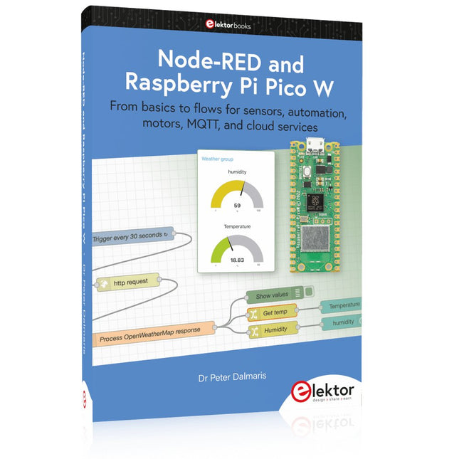
Elektor Publishing Node-RED and Raspberry Pi Pico W
From basics to flows for sensors, automation, motors, MQTT, and cloud services This book is a learning guide and a reference. Use it to learn Node-RED, Raspberry Pi Pico W, and MicroPython, and add these state-of-the-art tools to your technology toolkit. It will introduce you to virtual machines, Docker, and MySQL in support of IoT projects based on Node-RED and the Raspberry Pi Pico W. This book combines several elements into a platform that powers the development of modern Internet of Things applications. These elements are a flow-based server, a WiFi-enabled microcontroller, a high-level programming language, and a deployment technology. Combining these elements gives you the tools you need to create automation systems at any scale. From home automation to industrial automation, this book will help you get started. Node-RED is an open-source flow-based development tool that makes it easy to wire together devices, APIs, and online services. Drag and drop nodes to create a flowchart that turns on your lights at sunset or sends you an email when a sensor detects movement. Raspberry Pi Pico W is a version of the Raspberry Pi Pico with added 802.11n Wi-Fi capability. It is an ideal device for physical computing tasks and an excellent match to the Node-RED. Quick book facts Project-based learning approach. Assumes no prior knowledge of flow-based programming tools. Learn to use essential infrastructure tools in your projects, such as virtual machines, Docker, MySQL and useful web APIs such as Google Sheets and OpenWeatherMap. Dozens of mini-projects supported by photographs, wiring schematics, and source code. Get these from the book GitHub repository. Step-by-step instructions on everything. All experiments are based on the Raspberry Pi Pico W. A Wi-Fi network is required for all projects. Hardware (including the Raspberry Pi Pico W) is available as a kit. Downloads GitHub
€ 49,95
Members: € 44,96


