Elektor GREEN en GOLD leden kunnen deze uitgave hier downloaden.
Nog geen lid? Klik hier om een lidmaatschap af te sluiten.
OBD2-sensordashboardOude meters vormden het startpunt van een zoektocht naar echte gegevens
OBD2: voeg een toerenteller en schakelindicator toe aan je autoRetro, maar uiterst nuttig
LiDAR- en Visiesensoren voor Robotica
Sensor+Test 2025 en PCIM 2025
Contactloze E-Veldmetingen (1)Een Trillende Membraan voor het Detecteren van Gelijkspanningen of Statische Elektrische Velden
Draadloze brievenbusmeldervan optische sensoren tot radar: enkele mogelijkheden
Elektor Mini-Wheelieeen zelfbalancerende robot
ZonnecellenVreemde onderdelen, de serie
Aan de slag met een moderne radarsensorStaat een nauwkeurige meting op uw radar?
Uit het leven gegrepenpapierfabriek
CybersecurityZware tijden voor hackers
Infographics: IoT en sensoren 2025
Bluetooth 6.0 brengt verbeterde toepassingen voor afstandsbepalingNieuwe versie biedt betere apparaatpositionerings- en -locatieservices
Draadloze communicatie verkennen met BeagleY-AI
Err-lectronicsCorrecties, updates en lezerspost
Alle begin......sluit het thema opamps af
Een krachtige AI-codeerassistentsneller ontwikkelen met Continue en Visual Studio Code
Zonne-laadregelaar met MPPT (2)Het schema
Ultrasone obstakeldetectoreen eenvoudig project om slechtzienden te helpen
2025: Een AI-odysseeHalfjaaroverzicht
Raspberry Pi Standalone MIDI-synthesizer (3)Het slimmer maken en een gebruikersinterface toevoegen
Meshtastic: een demonstratieprojectEen slim netwerk van LoRa-radio's
Analoge audio-frequentiegeneratorHoogwaardige sinusgenerator met instelbare frequentie
This complete STM32 microcontroller programming course features a textbook, a component kit, hands-on projects, and a comprehensive online course. It is ideal for step-by-step learning of embedded systems programming in MicroPython using a practical, hands-on approach.
A Practical Introduction to Embedded Systems with the STM32
This course is designed for people who are new to embedded systems and looking for a structured, example-driven way to get started. A kit of parts comprising LEDs and resistors, switches, sensors and actuators, displays, a breadboard and wires, and more is included. These are used in the course to illustrate example applications.
No prior experience with MicroPython or embedded development is required. Each section features hands-on examples and mini projects designed to reinforce key concepts and inspire deeper exploration. By the end of the course, you’ll be able not only to reproduce the examples but also to build on them with your own ideas and applications.
What Will You Learn?
Microcontroller programming in MicroPython on the STM32 using the Thonny IDE
Working with Digital I/O, read buttons and encoders, control LEDs and relays
Read analog inputs, voltages, and analog sensors
Generating analog output signals and PWM
Use serial communication like UART, I²C and SPI to control displays and read digital sensors and SD cards
Managing time
Working with interrupts
Real-time sensor input and control via buttons, LEDs, and displays
Control actuators like relays and servo motors
Who Is It For?
Students and self-learners exploring embedded systems
Makers and IoT enthusiasts looking to improve their hardware skills
Educators and trainers seeking ready-to-teach material
What's Inside the Box?
Access to the full course on the Elektor Academy Pro Learning Platform
STM32 NUCLEO-F411RE microcontroller board
Book: MicroPython for STM32
Downloadable project files for every module
Component Box:
2× LED, red, 5 mm
LED, green, 5 mm
3× Resistor, 470 Ω, 0.25 W
LDR
Potentiometer, 10 kΩ, linear
Pushbutton
Rotary encoder module
Relay module
DHT22 Humidity & Temperature Sensor
TM1637-compatible 4-digit 7-segment display
MPU-6050 IMU with headers
SSD1306-compatible I²C OLED display
Micro SD card adapter with header
Buzzer
SG90 Micro Servo
ILI9341-compatible SPI 240×320 TFT display
20× Jumper wires
Breadboard
Le téléchargement intégral de ce numéro est disponible pour nos membres GOLD et GREEN sur le site Elektor Magazine !
Pas encore membre ? Cliquez ici.
tableau de bord OBD2Des cadrans anciens aux données en temps réel
OBD2 : ajoutez un compte-tours et un indicateur de changement de vitesse à votre voitureRétro, mais extrêmement utile
capteurs de vision et LiDAR pour la robotique
Sensor+Test 2025 et PCIM 2025
mesures sans contact du champ électrique (1)Membrane vibrante pour mesurer des tensions continues ou des champs électriques statiques
détecteur de courrier sans filCapteurs optiques, radars… quelques options à explorer
Elektor Mini-WheelieUn robot auto-équilibré
cellules solairesDrôles de composants, la série
premiers pas avec un capteur radar moderneUn capteur précis qui ne passe pas inaperçu
sur le vifUsine de papier
CybersécuritéDes temps difficiles pour les hackers
Infographie : IdO et capteurs
le Bluetooth 6.0 pour des applications de télémétrie amélioréesCette nouvelle version offre des fonctions de localisation améliorées
découvrez la communication sans fil avec BeagleY-AI
Projet 2.0Corrections, mises à jour et courrier des lecteurs
démarrer en électronique……Conclusion sur les ampli-op
un puissant assistant de codage de l'IAAccélérez votre développement avec Continue et Visual Studio Code
contrôleur de charge solaire avec MPPT (2)Le circuit
détecteur d'obstacles à ultrasonsUn projet simple pour aider les malvoyants
une odyssée de l'IABilan du premier semestre
synthétiseur MIDI autonome Raspberry Pi (3)plus intelligent avec une interface utilisateur
Meshtastic : un projet de démoUn réseau intelligent de noeuds LoRa
générateur analogique de fréquences audioGénérateur de signaux sinusoïdaux de haute qualité à fréquence réglable
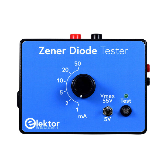
The Elektor Zener Diode Tester is essentially a constant-current source that can be switched in steps from 1 to 50 mA. It can be used to test Z-diodes up to a maximum of 54 V. Thanks to a 60-V step-up converter, the device can be powered by the usual 5 to 12 V.
The principle of this tester is straightforward. A Z-diode or other DUT (device under test, such as an LED) is biased by an adjustable current source. The voltage across the DUT can be measured with a multimeter. The voltage of most (small) Z-diodes is specified at a current of 5 mA. Depending on the application, the voltage at other currents can also be of interest. That is why six current settings are available: 1, 2, 5, 10, 20, and 50 mA. LEDs are often specified at a current of 20 mA.
What can be tested is:
Whether a Z-diode is defective (short circuit or high impedance).
Whether a Z-diode exhibits the correct Z-voltage.
How a Z-voltage changes with different currents.
What exact voltage is present at an integrated voltage reference.
Whether LEDs in a series chain differ in brightness (hence the 20 mA current).
What the current gain is for different base currents in (power) transistors.
The kit contains all parts listed in the bill of materials including PCB and enclosure.
Specifications
Supply voltage
5…12 V/2 A (USB-C)
Supply current (Itest = 50 mA)
1.1 A @ 5 V / 412 mA @ 12 V
Selectable currents
1, 2, 5, 10, 20, and 50 mA
Max. test voltage
>54 V @ Itest ≥1 mA
Max. output voltage
60 V @ Itest = 0 mA
Voltage limit at 5 V
4.5 V @ Itest = 1 mA / 5.18 V @ Itest = 50 mA
Enclosure dimensions
110 x 82 x 44 mm
PCB size
105.4 x 67.3 mm
Connections
4 mm banana sockets for multimeter
2 mm banana sockets for test clips
USB-C socket for power supply
Included
Resistors
R1 = 3.3 kΩ, 600 mW, 1%
R2 = 0.15 Ω, 1 W, 5%, LS 12.7 mm, ø 3.5 mm
R3, R8 = 180 Ω, 600 mW, 1%
R4, R6, R16 = 1 kΩ, 600 mW, 1%
R5, R19 = 47 kΩ, 600 mW, 1%
R7 = 3.9 kΩ, 1 W, 5%, LS 12.7 mm, ø 3.5 mm
R9, R10, R12 = 10 kΩ, 600 mW, 1%
R11, R13 = 100 Ω, 600 mW 1%
R14 = 249 Ω, 600 mW, 1%
R15 = 499 Ω, 600 mW, 1%
R17 = 2.49 kΩ, 250 mW, 1%
R18 = 4.99 kΩ, 250 mW, 1%
Capacitors
C1 = 470 uF / 35 V, 20%, Ir = 1.86 A, ø 12.5 mm, LS 5 mm, ESR = 0.038 Ω (Panasonic EEUTP1V471)
C2 = 1 uF / 100 V, 10%, X7R, LS 5 mm
C3 = 2.2 nF / 50 V, 10%, X7R, LS 5 mm
C4, C7 = 100 nF / 100 V, 10%, X7R, LS 5 mm
C5 = 100 uF / 100 V, 20%, ø 14 mm max., LS 5 mm
C6 = 1 nF / 100 V, 10%, X7R, LS 5 mm
Inductor
L1 = 100 uH, Irms = 2.4 A, Isat = 3.5 A, 0.09 Ω, radial, pitch 2.5/5/10 mm, ø 14 mm max. (Kemet SBC8-101-242)
Semiconductors
D1 = MUR120G, DO-41
D2, D4 = STPS3150RL, DO-201AD
D3 = Z-diode, 18 V, 1.3 W (BZX85C18)
D5 = Z-diode, 5.1 V, 0.5 W (1N5231B)
LED1 = LED in pushbutton S1
LED2 = LED, green, 3 mm
IC1 = MC34063, DIP-8
IC2 = LM4040BIZ-5.0/NOPB, TO-92 (TO-226AA-3)
IC3 = TL051CP, DIP-8
T1 = BC327.25, TO-92
T2 = STP40NF10L, TO-220
T3 = IRF9510PBF, TO-220
T4 = 2N7000, TO-92
Others
K1, K2, S1, S3 = 2-way screw terminal block, LS 3.5 mm, max. 1.5 mm²
connected to K1 = USB-C socket, 30 V/3 A, chassis mounted, wired, 9 x 16 mm
connected to K2 = Banana Connector, 2 mm, Socket, 60 VDC, Panel Mount, red (Multicomp 24.102.1)
connected to K2 = Banana Connector, 2 mm, Socket, 60 VDC, Panel Mount, black (Multicomp 24.102.2)
Test clip, red, 30 VAC/60 VDC (Hirschmann 931467101)
Test clip, black, 30 VAC/60 VDC (Hirschmann 931467100)
S1 = Pushbutton, panel mount, SPST-NO, 30 DC/100 mA, with red LED
S2 = Rotary Switch, 6 position, 2 pole, 30°, 250 V/150 mA
S3 = Toggle switch, panel mount, SPDT, solder lugs, 28 VDC
T2, T3 = Heat sink, 15°C/W, FK 214 SA-CB
Enclosure Hammond 1591XXSSBK, ABS, 110 x 82 x 44 mm
Knob for S2, round shaft 6 mm, ø 21 mm, with indicator line (Multicomp CP-LB21-6-6D)
4 x Self-tapping screw #4-1/4", carbon steel, pan head
Banana plug, red, 2 mm, 60 VDC (Multicomp 25.205.1)
Banana plug, black, 2 mm, 60 VDC (Multicomp 25.205.2)
Banana socket, black 4 mm, panel mount
Banana socket, red 4 mm, panel mount
for LED1, LED2 = Pin header, 1 x 2, vertical, pitch 2.54 mm
for LED1, LED2 = Pin socket, 1 x 2, vertical, pitch 2.54 mm
for T2, T3 = M3 screw, 10 mm, steel, pan head
2 x M3 washer, plain, steel
4 x M3 nut
for IC1, IC3 = DIP-8 socket
Wire, black, 0.25 mm² (24 AWG), stranded 14 x 0.15 mm, 1 m
Wire, red, 0.25 mm² (24 AWG), stranded 14 x 0.15 mm, 1 m
PCB 250772-1 v1.1
Links
Article
Elektor Labs
Learn, Build, and Understand Electronics – with Elektor
Projects, Expert Knowledge, Archive Access, and Exclusive Discounts – All in One Membership
Would you like to learn electronics, develop your own circuits, and gain a better understanding of modern technologies? Elektor Magazine has been one of the leading sources of information for electronics engineers, developers, start-ups, and companies for 65 years. With an Elektor Green Membership, you get:
✅ The international electronics magazine Elektor (in digital format)
✅ Access to the Elektor archive with 65 years of electronics know-how
✅ DIY projects, tested circuits, in-depth reviews and tutorials
✅ Exclusive member discounts at Elektor.com
Why Elektor?
For 65 years, Elektor has stood for in-depth electronics knowledge, practical projects, and innovative technologies.
From microcontrollers and embedded systems to Raspberry Pi, Arduino, and ESP32, as well as IoT, AI, measurement technology, audio, RF, and robotics, Elektor covers the key platforms and application areas of modern electronics.
Whether you are a beginner, maker, or professional – Elektor helps you take your skills to the next level.
Who Is This Membership for?
Beginners – Start your journey into electronics with clear fundamentals and first projects
Makers – Discover new projects, ideas, and inspiration for your own developments
Professionals & Engineers – Stay up to date with modern technologies and deepen your expertise
Your Benefits at a Glance
Magazine (Digital) – Receive every issue digitally, delivered straight to your inbox
65 Years of Electronics Knowledge – Access the extensive Elektor archive anytime (since 1974)
Hands-on Projects – Turn your ideas into reality with guides, circuits, and tutorials
Exclusive Discounts – Save on every purchase at Elektor.com
Unlock All Elektor Benefits Today!
Free Membership
Green Membership
❌ 8x Elektor Magazine (Digital Edition) as PDF
✅ 8x Elektor Magazine (Digital Edition) as PDF
❌ 12 Months of Access to the Full Elektor Archive
✅ 12 Months of Access to the Full Elektor Archive
❌ Access to Over 5,000 Gerber Files
✅ Access to Over 5,000 Gerber Files
❌ 10% Member Discount at Elektor.com
✅ 10% Member Discount at Elektor.com
✅ Read Elektor weekly every Friday
✅ Read Elektor weekly every Friday
ℹ️ Do you prefer reading Elektor Magazine in print? Find out everything about the Elektor Gold Membership (Print) here.
Open-Source-Code mit Arduino IDE und PlatformIO
Autonomes Fahren: GPS, Accelerometer, Gyroskop
PS3-Controller
Mikrocontroller wie der Arduino und Einplatinenrechner wie der Raspberry Pi haben sich zu beliebten Komponenten entwickelt. Dritter im Bunde ist der ESP32 der Firma Espressif. Mikrocontroller dieser Baureihe zeichnen sich durch eine Vielzahl implementierter Funktionen aus, die bei einem Arduino konventioneller Prägung mit einem Atmel-AVR-Mikrocontroller erst mit weiterer Hardware möglich sind. Prominentes Beispiel sind hier die WiFi- und Bluetooth-Funktionalitäten. Gegenüber einem Raspberry Pi zeichnen sie sich durch einen deutlich geringeren Preis aus.
Allgemeine Informationen für die Realisierung eines Roboterauto-Projekts mit dem ESP32 sind leicht zu finden. Dabei handelt es sich aber oft nur um Ausführungen zu einem Teilaspekt, ohne inhaltliche oder funktionale Abstimmung. So ist nicht nur die Beschaffung der benötigten Informationen mühselig und zeitaufwändig, sie kann auch außerordentlich fehlerträchtig sein.
Ansatzpunkt dieses Buches ist, diese Lücke zu schließen. Es geht auf verschiedene Möglichkeiten eines Chassis ein, vermittelt nötige Kenntnisse und führt schrittweise von einer einfachen Motorsteuerung zu einem komplexen sensor- und sprachgesteuerten Roboterauto. Hacks rund um GPS und eine PlayStation 3 runden die Sache ab.
Inhalt
Bei der Reihenfolge der Kapitel wurde versucht – beginnend bei der Darstellung von grundlegenden Informationen – über die Lösung einfacher Aufgaben zu etwas anspruchsvolleren Techniken zu führen.
Der Mikrocontroller ESP32
Die Software erstellen
Die Stromversorgung
Rund um die Hardware
Das Chassis
Der Gleichstrommotor
Kabellose Steuerung über WiFi
Mit Sensoren Hindernisse erkennen
Eine eigene Roboterauto-App
Servo und Lichtsensor
GPS
Accelerometer / Gyroskop
PS3-Controller
Roboterauto-App
Hinweis zur Software
Die Dateien haben das Suffix (.cpp). Grund ist die Entwicklung mit PlatformIO. Mit Copy & Paste sollten sie auch in der Arduino-IDE verwendet werden können.
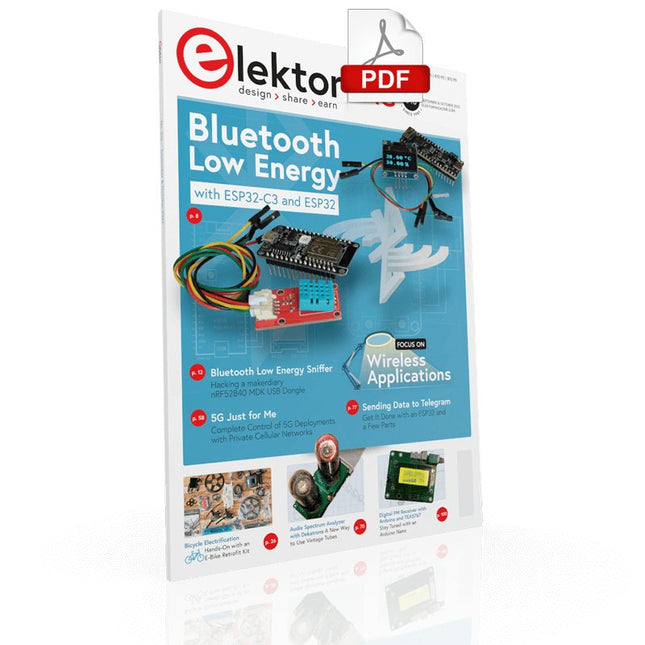
Elektor GREEN and GOLD members can download their digital edition here.
Not a member yet? Click here.
electronica fast forward 2022 Start- & Scale-Up AwardsPreparations Speeding Up!
Bluetooth Low Energy with ESP32-C3 and ESP32You Don’t Always Need to Choose Wi-Fi!
Bluetooth Low Energy SnifferHacking a makerdiary nRF52840 MDK USB Dongle
Magic RGB LED CubeHardware Design Around an RP2040
Auto On/Off for Solder Paste Compressor
Elektor Video ContentLivestreams, Webinars, and Courses for Engineers and Pro Makers
Bicycle ElectrificationHands-On with an E-Bike Retrofit Kit
Starting Out in ElectronicsMultiplying Voltages
From Life’s ExperienceSidelines
Teensy 4.0Why Is This Board So Fast?
Audio Power Amplifier Simulation with TINAThe Try-Before-You-Build Approach
Develop and Operate Your LoRaWAN IoT NodesSample Chapter: Dragino LHT65, LDS01, and LDS02 LoRaWAN Modules
Err-lectronicsCorrections, Updates and Readers’ Letters
5G Just for MeGaining Complete Control of 5G Deployments with Private Cellular Networks
Infographics 7-8/2022
How Does My Device Learn to Transmit?Applications with Wi-Fi Interfaces
Smartphones are the Heart of the IoT
Audio Spectrum Analyzer with DekatronsA New Way to Use Vintage Tubes
Sending Data to TelegramGet It Done with an ESP32 and a Few Parts
A Fliege Notch Filter for Audio MeasurementsMake Better Measurements with a Notch Filter
CO2 Meter TeardownIs It Hackable for Your Projects?
PUT-ting It All TogetherThe Programmable Unijunction Transistor Explained
Round Touchscreen for Raspberry PiHyperPixel 2.1 Round from Pimoroni
Remote Sensing with Connection Loss DetectionUsing nRF24L01+ Modules
Digital FM Receiver with Arduino and TEA5767Stayed Tuned with an Arduino Nano
Changing an OLED Interface from SPI to I²C
HomeLab ToursA Hobby Does Not Retire
A Decade of Ethics in ElectronicsTessel Renzenbrink Reflects on the Digital Society and More
HexadokuThe Original Elektorized Sudoku
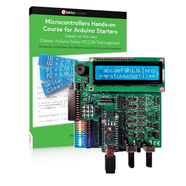
Realize your own projects with the Elektor Arduino Nano MCCAB Training Board
The microcontroller is probably the most fascinating subfield of electronics. Due to the multitude of functions, it combines on its chip, it is a universal multi-tool for developers to realize their projects. Practically every device of daily use today is controlled by a microcontroller. However, for an electronic layman, realizing his own ideas with a microcontroller has so far remained a pipe dream due to its complexity. The Arduino concept has largely simplified the use of microcontrollers, so that now even laymen can realize their own electronics ideas with a microcontroller.
Book & Hardware in the Bundle: 'Learning by Doing'
This book, which is included in the bundle, shows how you can realize your own projects with a microcontroller even without much experience in electronics and programming languages. It is a microcontrollers hands-on course for starters, because after an overview of the internals of the microcontroller and an introduction to the programming language C, the focus of the course is on the practical exercises. The reader acquires the necessary knowledge by 'learning by doing': in the extensive practical section with 12 projects and 46 exercises, what is learned in the front part of the book is underpinned with many examples. The exercises are structured in such a way that the user is given a task to solve using the knowledge built up in the theoretical part of the book. Each exercise is followed by a sample solution that is explained and commented on in detail, which helps the user to solve problems and compare it with his own solution.
Arduino IDE
The Arduino IDE is a software development environment that can be downloaded for free to your own PC and that contains the entire software package needed for your own microcontroller projects. You write your programs ('apps') with the IDE’s editor in the C programming language. You translate them into the bits and bytes that the microcontroller understands using the Arduino IDE's built-in compiler, and then load them into the microcontroller's memory on the Elektor Arduino MCCAB Nano Training Board via a USB cable.
Query or control external sensors, motors or assemblies
In addition to an Arduino Nano microcontroller module, the Elektor Arduino Nano MCCAB Training Board contains all the components required for the exercises, such as light-emitting diodes, switches, pushbuttons, acoustic signal transmitters, etc. External sensors, motors or assemblies can also be queried or controlled with this microcontroller training system.
Specifications (Arduino Nano MCCAB Training Board)
Power Supply
Via the USB connection of the connected PC or an external power supply unit (not included)
Operating Voltage
+5 Vcc
Input Voltage
All inputs
0 V to +5 V
VX1 and VX2
+8 V to +12 V (only when using an external power supply)
Hardware periphery
LCD
2x16 characters
Potentiometer P1 & P2
JP3: selection of operating voltage of P1 & P2
Distributor
SV4: Distributor for the operating voltagesSV5, SV6: Distributor for the inputs/outputs of the microcontroller
Switches and buttons
RESET button on the Arduino Nano module 6x pushbutton switches K1 ... K6 6x slide switches S1 ... S6 JP2: Connection of the switches with the inputs of the microcontroller
Buzzer
Piezo buzzer Buzzer1 with jumper on JP6
Indicator lights
11 x LED: Status indicator for the inputs/outputs LED L on the Arduino Nano module, connected to GPIO D13 JP6: Connection of LEDs LD10 ... LD20 with GPIOs D2 ... D12
Serial interfacesSPI & I²C
JP4: Selection of the signal at pin X of the SPI connector SV12 SV9 to SV12: SPI interface (3.3 V/5 V) or I²C interface
Switching output for external devices
SV1, SV7: Switching output (maximum +24 V/160 mA, externally supplied) SV2: 2x13 pins for connection of external modules
3x3 LED matrix(9 red LEDs)
SV3: Columns of the 3x3 LED matrix (outputs D6 ... D8) JP1: Connection of the rows with the GPIOs D3 ... D5
Software
Library MCCABLib
Control of hardware components (switches, buttons, LEDs, 3x3 LED matrix, buzzer) on the MCCAB Training Board
Operating Temperature
Up to +40 °C
Dimensions
100 x 100 x 20 mm
Specifications (Arduino Nano)
Microcontroller
ATmega328P
Architecture
AVR
Operating Voltage
5 V
Flash Memory
32 KB, of which 2 KB used by bootloader
SRAM
2 KB
Clock Speed
16 MHz
Analog IN Pins
8
EEPROM
1 KB
DC Current per I/O Pins
40 mA on one I/O pin, total maximum 200 mA on all pins together
Input Voltage
7-12 V
Digital I/O Pins
22 (6 of which are PWM)
PWM Output
6
Power Consumption
19 mA
Dimensions
18 x 45 mm
Weight
7 g
Included
Elektor Arduino Nano MCCAB Training Board
Arduino Nano
Book: Microcontrollers Hands-on Course for Arduino Starters
Le téléchargement intégral de ce numéro est disponible pour nos membres GOLD et GREEN sur le site Elektor Magazine !
Pas encore membre ? Cliquez ici.
qu’est-ce que l’edge AI ?L’IA, intégrée à l’appareil
découvrez Edge Impulse StudioConcevez et déployez facilement des modèles d’IA en périphérie
détection de mots-clés avec Edge ImpulseCollecter, entraîner et déployer
contrôle d’appareils par commande vocale avec le Nordic Thingy:53
Termes clés pour comprendre l’edge AI et le machine learning
cours accéléré : démarrez avec Edge ImpulseApprenez à collecter, entraîner et déployer un modèle ML avec l’Arduino Nano 33 BLE Sense
un nouveau chapitre pour ArduinoD’une carte pour amateurs à une plateforme d’edge computing
premiers pas avec la détection d’objets sur des appareils edge
détection de défauts sur circuits imprimésVision par ordinateur avec Raspberry Pi
adapter l’IA aux appareils les plus compacts
optimiser l’efficacité énergétique des appareils edge AI alimentés sur batterie
grille-pain intelligentL’IA qui reconnaît le toast parfait
Thundercomm Rubik Pi 3Raspberry Pi et l’edge AI, enfin réunis
Leadership, ML embarqué et révolution de l’IA en périphérie
modèles vision-langage en périphérieCascade de modèles pour une meilleure fiabilité
découvrez Edge ImpulseQuestions de la communauté Elektor
mise à jour du projet n°5 : Compteur d’énergie ESP32Utiliser l’Edge AI pour identifier les charges domestiques
reconnaissance de mouvements avec détection d’anomaliesUn tutoriel détaillé
système de ventilation intelligent : fusion des données sonores et environnementalesUtilisation d’un microcontrôleur double-cœur et du ML pour l’automatisation des fenêtres et persiennes
intégrer la commande vocale aux écouteurs et aux casques
l'IA en périphérie : au cœur des appareils de demain
Le téléchargement intégral de ce numéro est disponible pour nos membres GOLD et GREEN sur le site Elektor Magazine !
Pas encore membre ? Cliquez ici.
l'ESP-BLASTUn mini drone-fusée ESP32 qui vole à plus de 100 km/h
atelier sans fil (1)Modules radio déverrouillés : émetteur-récepteur sub-GHz CC1101 433 MHz
émetteur AMAvec le générateur d'ondes carrées/sinusoïdales sur Raspberry Pi Pico
STM32Cube Innovation ChallengeParticipez avec votre meilleur projet STM32C5
CoffeeCallerComment une pause café a inspiré un PCB sur mesure
audiotroniquesDistorsion harmonique totale
Elektor à 65 ansProjets de septembre et octobre au fil des ans
Bluetooth Channel Sounding pour le suivi des équipementsMesure de distance avec une précision centimétrique pour l’IoT de nouvelle génération
2026 : une Odyssée de l'IAL'informatique quantique n'est pas le prochain GPU
protéger le cloud exige de sécuriser la périphérie
premières expériences avec le HackRF ProTests pratiques avec le nouveau matériel SDR
mise à niveau du modem de GPRS/2G vers LTE/4GExemple d'un panneau de contrôle d'alarme sans fil
antenne en bouclePartie 1 : Une antenne ondes courtes à directivité réglable, à réaliser soi-même
convertisseur de radio Internet en AMUn ESP32-S3 comme émetteur
projet 2.0
mioty : aperçu généralL'approche de Fraunhofer pour les LPWAN
sagesse d'atelierConseils pratiques d'experts
Walter, le module IoT compactPartie 2 : Accéder aux services météorologiques et aux services de données