
Search results for "rfid OR starter OR kit OR for OR arduino OR uno"
-

Elektor Digital Arduino – Schaltungsprojekte für Profis (PDF)
Mit Arduino – Schaltungsprojekte für Profis wird der Leser umfassend in die Hardware und Software der Arduino-Plattform eingeführt. Einfache, leicht verständliche Projekte am Anfang des Buches führen Schritt für Schritt in die Open-Source-Plattform ein. Die Projekte werden dann zunehmend komplexer, um dem Leser möglichst viele konkrete Lösungsmöglichkeiten aufzuzeigen, die mit dem Arduino-Mikrocontroller auch für angehende Profis zur Verfügung stehen. Dabei wird neben den erforderlichen theoretischen Grundlagen stets größter Wert auf eine praxisorientierte Ausrichtung gelegt. So werden wichtige Techniken wie AD-Wandlung, Timer oder Interrupts stets in Praxisprojekte eingebettet. Es entstehen Lauflichteffekte, ein Aufwachlicht, voll funktionsfähige Voltmeter, präzise Digitalthermometer, Uhren in allen Variationen, Reaktionszeitmesser oder mausgesteuerte Roboterarme. Und ganz nebenbei hat der Leser die Grundlagen der zugehörigen Controller-Technik verstanden und im wahrsten Sinne des Wortes begriffen.
€ 34,80
Members: € 31,32
-

Elektor Digital AVR-Mikrocontroller (PDF)
Programmierung in Assembler und C am Beispiel der ATtiny-Familie Dieses Buch bietet einen eingehenden Blick auf die 8-Bit-AVR-Architektur in ATtiny- und ATmega-Mikrocontrollern, hauptsächlich aus der Sicht der Software und der Programmierung. Erforschen Sie die AVR-Architektur unter Verwendung von C und Assembler in Microchip Studio (früher Atmel Studio) mit ATtiny-Mikrocontrollern. Lernen Sie die Details der internen Funktionsweise von AVR-Mikrocontrollern kennen, einschließlich der internen Register und des Speicherplans von ATtiny-Bausteinen. Programmieren Sie ATtiny-Mikrocontroller mit einem Atmel-ICE-Programmiergerät/Debugger oder verwenden Sie ein preiswertes Hobby-Programmiergerät oder sogar einen Arduino Uno als Programmiergerät. Die meisten Code-Beispiele können mit dem Microchip Studio AVR-Simulator ausgeführt werden. Lernen Sie, Programme für ATtiny-Mikrocontroller in Assembler zu schreiben. Erfahren Sie, wie Assemblersprache in Maschinencodebefehle umgewandelt wird. Finden Sie heraus, wie Programme, die in der Programmiersprache C geschrieben wurden, in Assemblersprache und schließlich in Maschinencode umgewandelt werden. Verwenden Sie den Microchip Studio Debugger in Kombination mit einem Hardware-USB-Programmierer/Debugger, um Assembler- und C-Programme zu testen oder verwenden Sie den Microchip Studio AVR-Simulator. ATtiny-Mikrocontroller im DIP-Gehäuse werden verwendet, um eine einfache Nutzung auf Breadboards zu ermöglichen. Erfahren Sie mehr über Timing und Taktimpuls in AVR-Mikrocontrollern mit ATtiny-Bausteinen. Werden Sie zu einem AVR-Experten mit fortgeschrittenen Debugging- und Programmierfähigkeiten.
€ 32,80
Members: € 29,52
-

Elektor Digital Elektor Mei/Juni 2020 (PDF)
Open-netwerk weerstation mk2deel 1: inleiding en hardware-elementen AI voor beginners (1)objectherkenning met het Maixduino-board Universele triac-stuurmodule met ATmegaschakelen en dimmen van verschillende belastingen Hoe... iets van GitHub downloadenGitHub Voor Dummies My IoT-Button: de knop voor het netdeel 2: prototyping met board en cloud TMS0280 spraaksynthesizervreemde onderdelen Interactiefcorrecties & updates | vragen & antwoorden BASIC voor ESP32/ESP8266 (2)zandloper met ESP8266 en Annex WiFi RDS Developer’s Zonetips & trucs, vakkunstigheden en andere nuttige informatie BalBot: een zelfbalancerende robotmoderne versnellingssensoren vergemakkelijken de bouw Alle begin......hoeft niet zo moeilijk te zijn Wie het kleine niet eertuit de ideeënbus van Elektor Verzendbox met manipulatie-indicatiegegevens veilig met de post verzenden Nieuwe Nauwkeurige Nixie-klok: verbeteringentechnisch nieuwsbulletin voor nieuwe en bestaande enthousiaste gebruikers Multitasking met de ESP32 (3)software-timers Met de vos in het IoT (4)inrichten van het dashboard Start-up update: het Elektor Investment Program Review: Elektronische USB-belasting Joy-IT HD35test de belastbaarheid van USB-poorten CAN-bus + Arduino houden zonnepanelen in de gatenlokaliseer panelen in grote arrays die onderhoud nodig hebben Analoge elektronica ontwerpencase-study #1 – deel 3: optimalisatie van de responsie van de voorversterker en compromissen Sound Blinkdraagbare zelfbouwspeaker met LED-lichtshow USB-stroombewakingintelligente bescherming voor USB-poorten Oost West Lab Besteen blik in het allerheiligste, waar onbevoegden geen toegang hebben... Review: Labvoeding PeakTech 6080 Aveel voeding voor weinig geld Een grote uitdagingveilige producten in het IoT-tijdperk Elektor 1,2-GHz-universeelteller (1992/93)voorbij de magische 1GHz-grens Hexadoku
€ 9,95
-

Elektor Digital Elektor Novembre/Décembre 2022 (PDF)
Le téléchargement intégral de ce numéro est disponible pour nos membres GOLD et GREEN sur le site Elektor Magazine ! Pas encore membre ? Cliquez ici. Le haut de gamme au c?ur du labo Elektor Amplificateur haut de gamme Fortissimo-100Étage de sortie audio entièrement symétrique avec 100/190 W Vérification de la fréquence des quartz et des circuits accordésAstuces, bonnes pratiques et autres informations utiles trucs et astuces pour circuits imprimés souder - et alors??un regard approfondi sur la technologie de soudage moderne commande de porte de garage par Bluetooth à réponse rapideOuvrez votre porte avec votre smartphone contrôleur de diode idéalecircuits à diodes à faible dissipation de puissance guirlandes de LED avec ESP32 et FreeRTOSclignotantes et scintillantes démarrer en électronique...avec plaisir, on continue avec les Zener récepteur FM/DAB+le meilleur des deux mondes sur le vifElectronica Obscura procédé sans fil de débogage de micrologicielsTampon circulaire et serveur web sur l?ESP32 Le COVID-19 a-t-il donné un coup de fouet à l?innovation en ingénierie ?Composants et solutions innovants de 2022 Ersa i-CON TRACE ? la station de soudage connectée pour professionnels Infographiques qu?allons-nous faire de toute cette informatique ? Comment piloter l?afficheur E-Paper d?Ynvisible innovation de tous les instants chez InnoFaithentretien avec Walter Arkesteijn automatisation industriellerétrofit IdO facile et évolutif Qt pour le Raspberry Piguide pas à pas pour la configuration du framework d'interface graphique utilisateur Les connecteurs linéaires ultra-plats facilitent la gestion de données multi-signaux intelligents - innovants - rentablesles FPGA GateMate conçus et fabriqués en Allemagne des outils pour soutenir le développement de capteurs à faible coût fusible réarmable CTPdrôle de composant, la série Sortie analogique isolée pour Arduino Uno visite à domicile? Découvre le Thérémine electronica fast forward 2022 ? une initiative d?Elektoréquipe et calendrier radiogoniométrieretrouver les capteurs météo sans fil égarés estimer le bruit interne d?un circuit intégréméthode simple Questions d?éthiqueInitié par le WEEF Éthique et profit, un mariage de raisonEntretien avec le professeur Stefan Heinemann l?index WEEF 2023 logiciel de calcul de filtresOutils de conception de filtres analogiques Éteins-moi cette télé !avec TV-B-Gone Mesure de la qualité de l?air avec le RP2040 elekterminal Initiation à Python 3extrait du chapitre : bibliothèque Wand et traitement numérique des images SOLARPUNKun avenir prometteur Hexadoku
€ 10,95
-

Elektor Labs Elektor Low-Noise Lab Power Supply
The Elektor Low-Noise Lab Power Supply is a fully analogue, adjustable, medium-power symmetrical bench supply that contains no switching or digital components. It provides an output voltage adjustable between 0 V and ±22 V, and an output current adjustable from 0 A to 1 A. Because it avoids any form of switching circuitry, the design delivers extremely low noise. To display both output voltages and currents, four miniature moving-coil panel meters are used. Most modern laboratory power supplies and AC adapters employ switch-mode techniques. Even the best examples inevitably exhibit high-frequency ripple and other switching artefacts on their output, which can interfere with the testing of sensitive analogue circuits and disturb low-level measurements. To overcome this, the concept here is a completely analogue power supply. Although less efficient than its switch-mode counterparts, the reduced efficiency is of little importance for test-bench use and ensures cleaner, more reliable measurement results. Because many analogue circuits require a symmetrical supply, this design delivers positive and negative output voltages of equal magnitude. A small amount of adjustment is available to compensate for any imbalance. Naturally, a variable current-limit function is also included. The kit includes the components required to build the power supply, except for the transformers. Specifications Output Voltage 0…+22 V, 0, −22 V Output Current 0…+1 A, 0…−1 A Noise −85 dBV, (at 0.95 A/20 V, B = 22 kHz) −84 dBV (at 0.95 A/20 V, B > 500 kHz) Ripple 50 µVRMS (at 950 mA/20 V, B = 22 kHz, mainly 100 Hz component) Included 3x PCBs: Regulator (PCB-1), Mains Filter (PCB-2) and Transformer (PCB-3) All the components except the AC transformers 4x moving-coil meters Additional parts for wiring (wires, banana sockets, IEC Power entry module, etc.) Not included The three AC transformers An enclosure Parts List For the Regulator PCB (240386-1) Resistors (250 mW, 1%) R1 = 12 Ω R2, R8, R37, R62 = 1 MΩ R3, R7, R10, R13, R17, R20, R22, R30, R35, R42, R45, R47, R55, R60 = 100 Ω, 600 mW R4, R5 = 4.7 kΩ R6 = 100 kΩ R9, R12, R14, R36, R38, R39, R61, R63, R66, R72, R78, R79 = 10.0 kΩ, 600 mW R11 = 9.76 kΩ, 600 mW R15, R40 = 44.2 kΩ, 600 mW R16, R41, R77 = 1 kΩ R18, R43 = 1.5 kΩ, 1 W, 5% R19, R44 = 470 Ω, 1 W, 5% R21, R46 = 330 Ω, 600 mW R23, R24, R48, R49 = 1.0 Ω, 1 W R25, R50 = 1 kΩ, 1 W, 5% R26, R28, R51, R53 = 1.000 kΩ 0.1%, 15 ppm/C R27, R29, R52, R54 = 10.00 kΩ 0.1%, 15 ppm/C R31, R56 = 1.2 kΩ, 1 W, 5% R32, R57 = 47 kΩ R33, R58 = 270 Ω R34, R59 = 27 kΩ R64, R69 = 12.0 kΩ R65 = 3.0 kΩ, 600 mW R67, R80 = 470 Ω, 600 mW R68, R70 = 6.8 kΩ, 600 mW R71 = 30.0 kΩ,, 600 mW R73, R74, R75, R76 = 10 MΩ P1, P2, P3 = 10 kΩ, 200 mW, 20%, potentiometer, 1 turns, single, lin., panel mount P4, P5 = 500 Ω, 500 mW, 10%, trimmer, 25 turns, 3296Y-1-501LF Bourns P6, P7 = 10 kΩ, 500 mW, 10%, trimmer, 25 turns, 3296Y-1-501LF Bourns Capacitors C1 = 100 nF, 50 V, 10%, ceramic X7R, LS 5 mm C2, C3, C6, C7, C30 = 10 µF, 63V, 20%, LS 2.5 mm, 3000hours@105°C C4, C5, C8, C9, C13, C14, C18, C19, C23, C24, C28, C29, C31, C32, C38, C39 = 100 nF, 250 V, 10%, PET, LS 7.5 mm C10, C20 = 47 nF, 100 V, 5%, PET, LS 5 mm C11, C21 = 10 nF, 100 V, 5%, PET, LS 5 mm C12, C22 = 220 µF, 35 V, 20%, 0.024 Ω, LS2.5/3.5 mm, Ir 3.4 A, 2000hours@125°C, polymer C15, C25 = 120 µF, 50 V, 20%, ESR 0.02 Ω, Diam. 10 mm max., LS 5 mm C16, C26 = 15 nF, 100 V, 5%, PET, LS 5 mm C17, C27 = 47 nF, 100 V, 5%, PET, LS 5 mm C33, C34 = 22 µF, 50 V, 20%, LS 2 mm, 10000 hours @ 105°C C35, C36, C44, C45 = 1 µF, 100 V, 10%, LS 5 mm, ceramic X7R C37 = 100 uF, 50 V, 20%. LS 3.5 mm C40, C41, C42, C43, C46, C47, C48, C49 = 1000 µF, 50 V, 20%, LS 5/7.5 mm, Ir 3.32 A, 10000hours@105°C, D 16 mm C50, C51, C52, C53 = 47 nF, 100 V, 10%, ceramic X7R, LS 5 mm Inductors L1, L2 = 4.7 µH, 3.2 A, 0.033 Ω, LS 5 mm, RLB0914-4R7ML Bourns L3 = Commom mode choke, 14.5 mH, 3 A, SSRH24NH-30145 Kemet Semiconductors D1, D2, D3, D4, D5, D9, D10, D11, D15 = BAT85, DO-34 D6, D7, D12, D13 = SR560, DO-201AD D8, D14, D16 = 1N4148, DO-35 D17 = Zenerdiode, 5.6 V, 0.5 W, DO-41 D18, D19 = 1N4004, DO-41 D20, D21 D22, D23 = V30100CI-M3/P, dual common cathode, TO-220 D24 = Zener diode, 30 V, 1 W, DO-41 LED1, LED2 = LED, red, T-1 (3 mm) LED3, LED4 = LED, green, T-1 (3 mm) TVS1, TVS2 = BZW50-33B, R6 T1, T2, T4 = BC337.25, TO-92 T3 = NJW0302G, TO-3P T5, T6, T8 = BC327.25, TO-92 T7 = NJW0281G, TO-3P T9 = BD139, TO-126 (SOT-32) IC1 = LM334Z, TO-92 IC2 = LM4040AIZ-5.0/NOPB, TO-92 (TO-226AA-3) IC3, IC4 = OPA2992IDR, SOIC-8 IC5, IC6 = OPA4992IDR, SOIC-14 IC7 = OPA992IDBVR, SOT-23-5 IC8 = LM339N, DIP-14 IC9 = LM317, TO-220 IC10 = LM337, TO-220 Others F1, F2 = 5×20 mm fuse, 1.6 A, fast acting HS1, HS2 = Heatsink MC33271 (for T3/T7), 2.7°C/W, PCB mount, height 63.5 mm K1, K4 = 3-way screw terminal block, LS 3.5 mm, max. 1.5 mm² K2, K3 = 3-way screw terminal block, LS 3.5 mm, max. 1 mm² M1, M3 = Moving coil meter, Range 30 V, type 91C4, 45×45 mm M2, M4 = Moving coil meter, Range 1 A, type 91C4, 45×45 mm² RE1 = Relay DPDT,5V, UA2-5NU Miscellaneous 3× 3-way screw terminal block, LS 3.5 mm, max. 1 mm² (for P1, P2, P3) 4× Pin header, 1×2, vertical, pitch 2.54 mm (for LED1, LED2, LED3, LED4) 4× Pin socket, 1×2, vertical. pitch 2.54 mm (for LED1, LED2, LED3, LED4) 2× Heatsink FK222SA220, 20°C/W, PCB mount (for IC9 & IC10) 2× Mica thermal pad for TO-220, 12×18×0.05 mm (for IC9 & IC10) 2× Insulating bushing IB 6, TO-220 (for IC9 & IC10) 2× Ceramic thermal pad, 23×20×2 mm (for T3 & T7) 2× PCB Fuse Holder, for 5×20 mm fuse, 10 A (for F1, F2) 2× Cover for PCB Fuse Holder, transparent (for F1, F2) 2× 2-way screw terminal block, LS 3.5 mm, max. 1 mm² (for M1 & M3) 2× 2-way screw terminal block, LS 3.5 mm, max. 1.5 mm² (for M2 & M4) 8× M3 solder lug, thickness 0.35 mm (for M1…M4) M4 solder lug, thickness 0.35 mm (to connect 4 mm banana connectors) Screened cable, 1 pair, 2×24 AWG/0.22 mm², 1 m (for P1, P2 & P3) IC socket, DIP, 14 contacts (for IC8) M3 washer, plain, steel M3 screw, 16 mm, steel, pan head M3 nut M3 spring washer 50 mm M3 standoff, steel, male-female 12 mm M3 standoff, steel, male-female 10 mm M3 standoff, steel, male-female M3 screw, 8 mm, steel, pan head For the Mains Fiter PCB (240386-2) Resistor R1 = 220 kΩ, 1 W, 500 V, 5% Capacitors C1, C2 = 470 nF, 305 VAC, Class X2, 11 × 27 mm max., LS 15/22.5 mm C3, C4, C5, C6 = 2.2 nF, 300 VAC, Class Y2, 13 × 4 mm, LS 10 mm, PP Inductors L1, L2 = Common-mode choke, 6.8 mH, 1.7 A, TDK B82732R2172B030 Semiconductor MOV1 = TVS varistor, 300 VAC, S14K300 (230 VAC, B72214S0301K101) and SK14K150 (150 VAC, B72214S0151K101) Others K1, K2 = 3-way screw terminal block, LS 7.62 mm F1 = Time-delay fuse, 0.5 A (230 VAC) or 1 A (115 VAC) Miscellaneous 1× Fuse holder, 5×20 mm, 10 A, 500 VAC 1× Transparent fuse cover 4× 10 mm M3 standoff, steel, male–female 4× M3 screw, 8 mm, steel, pan head 4× M3 nut For the Transformer PCB (240386-3) Resistors R1, R2 = 2.7 kΩ, 600 mW, 1% R3 = 10.0 kΩ, 600 mW, 1% Capacitor C1 = 220 µF, 50 V, 20%, Ø10 mm, LS 5 mm, 4000 h @ 105°C Transformers (not included in this kit!) TR1, TR2, TR3 = 2×7 V, 25 VA, PCB-mounted toroid, 70060K Talema Semiconductors D1–D4 = 1N4148, DO-35 D5, D6 = 1N4004, DO-41 D7 = Zener 5.6 V, 1.3 W, DO-41 LED1 = LED, red, T-1 (3 mm) IC1, IC2 = MOC8021M, CTR ≥ 1000%, DIP-6 Others F1, F2, F3 = 160 mA time-delay fuse (230 VAC) or 315 mA time-delay fuse (115 VAC) K1 = 2-way screw terminal block, LS 7.62 mm K2 = 3-way screw terminal block, LS 3.5 mm, max 1.5 mm² K3, K4 = 3-way screw terminal block, LS 3.5 mm, max 1 mm² RE1, RE2 = Relay DPDT, 5 A/250 VAC / 24 VDC Miscellaneaous 1× Pin header 1×2, pitch 2.54 mm + matching socket for LED1 3× Fuse holder 5 × 20 mm, 10 A, 500 VAC + transparent cover 3× M4 screw, 8 mm, pan head + washer for TR1-TR3 8× M3 screw, 8 mm, pan head + nut + washer 8× 10 mm M3 standoff, steel, male–female 2× IC socket, DIP-6 for IC1 & IC2 Additional Parts 1 m red insulated wire, stranded, 1.5 mm² 0.5 m blue insulated wire, stranded, 1.5 mm² 0.5 m black insulated wire, stranded, 1.5 mm², 0.5 m 2 m red insulated wire, stranded, D 0.56 mm (0.25 mm²) 2 m black insulated wire, stranded, D 0.56 mm (0.25 mm²) 0.5 m Multicore Cable, Flexible, 3 Core, 0.75 mm² (24 x 0.2 mm) Red banana socket Black banana socket Blue banana socket Green banana socket IEC Power Entry Module with switch, IEC C14 3 crimp terminals, FASTON, 4.75 x 0.81 mm 3 knobs Links Elektor Labs JumpStarter Page Article (Part 1) Article (Part 2)
€ 299,00€ 249,00Best Price
-
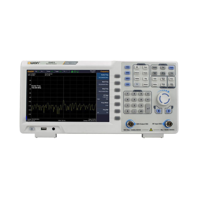
OWON OWON XSA815-TG Spectrum Analyzer (9 kHz – 1.5 GHz)
The OWON XSA815-TG (9 kHz-1.5 GHz) is a cost effective spectrum analyzer with tracking generator included and a frequency resolutions of 1 Hz. Features Frequency Range from 9 kHz to 1.500009 GHz 9-inch display 9 kHz to 1 MHz -95 dBm Displayed Average Noise Level, 1 MHz to 500 MHz 140 dBm (Typical), <-130 dBm Phase Noise -10 kHz <-80 dBc/Hz 100 kHz <-100 dBc/Hz 1 MHz <-115 dBc/Hz Resolution Bandwidth (-3 dB): 1 Hz to 1 MHz, in 1-3-5-10 sequence Tracking Generator Kit: 100 kHz to 1.500009 GHz Specifications Frequency Range 9 kHz to 500.009 MHz Frequency Resolution 1 Hz Frequency Span 9 kHz to 1.500009 GHz Span Range 0 Hz, 100 Hz to max frequency of instrument Span Uncertainty ±span / (sweep points-1) SSB Phase Noise (20°C to 30°C, fc=1 GHz) Carrier Offset 10 kHz <-80 dBc/Hz | 100 kHz <-100 dBc/Hz | 1 MHz <-115 dBc/Hz Resolution Bandwidth (-3 dB) 1 Hz to 1 MHz, in 1-3-5-10 sequence RBW Accuracy <5% typical Resolution Filter Shape Factor (60 dB: 3 dB) <5 typical Video Bandwidth (-3 dB) 10 Hz to 1 MHz, in 1-3-5-10 sequence Amplitude measurement range DANL to +10 dBm, 100 kHz to 10 MHz, Preamp Off DANL to +20 dBm, 10 MHz to 1.5 GHz, Preamp Off Reference Level -80 dBm to +30 dBm, 0.01dB by step Preamp 20 dB, nominal, 100 kHz to 1.5 GHz Input Attenuator 0 to 40 dB, 1 dB by step Display Average Noise Level Input attenuation = 0 dB, RBW = VBW = 100 Hz, sample detector, trace average ≥ 50, 20°C to 30°C, input impedance = 50 Ω) Preamp Off 9 kHz to 1 MHz -95 dBm (Typical), <-88 dBm Preamp Off 1 MHz to 500 MHz -140 dBm (Typical), <-130 dBm Preamp On 100 kHz to 1 MHz -135 dBm (Typical), <-128 dBm Preamp On 1 MHz to 500 MHz -160 dBm (Typical),<-150 dBm Tracking Generator (optional) Frequency Range 100 kHz to 1.500009 GHz Output power level range -40 dBm to 0 dBm Output level resolution 1 dB Output flatness Relative to 50 MHz | ±3 dB Tracking generator spurious Harmonic spurious -30 dBc (Tracking generator output power -10 dBm) Non-harmonic spurious -40 dBc (Tracking generator output power -10 dBm) Tracking generator to input terminal isolation -60 dB (Tracking generator output power 0 dBm) Tracking generator to input terminal isolation -60 dB (Tracking generator output power 0 dBm) Tracking generator to input terminal isolation -60 dB (Tracking generator output power 0 dBm) Dimensions 375 x 185 x 120 mm Weight 3.7 kg Included 1x XSA815-TG 1x 220 V AC power cord 1x USB Cable 1x Quickstart guide Downloads Quick Guide Specifications
€ 907,50
-

Elektor Digital Elektor July/August 2026 (PDF) EN
Elektor GREEN and GOLD members can download their digital edition here. Not a member yet? Click here. MultiRF Dev BoardA Platform for Evaluating Short- and Long-Range Wireless Protocols Elektor at 65Disrupting Electronics Since 1961 Wi-Fi-Based Person Detection on an ESP32When Your Router Becomes a Motion Sensor Wireless ScalesFour Small Scales = One Big Scale Walter, the Compact IoT ModuleESP32-S3 SoC, LTE-M/NB-IoT 5G Modem, and GNSS Receiver 3- and 4-Wire RTD Sensors ConditioningWith Full-Scale Adjustment and Cable Compensation 3-in-1 2-Channel Oscilloscope/Generator/MultimeterA Review of The Fnirsi 2D15P electronica Fast Forward 2026 Invites Startups and Industry Partners EcologgingA Modular Environmental IoT Station for Field Research Wireless Connectivity in Medical ApplicationsAlways on the Pulse with Bluetooth LE AudiotronicsHum Reduction Increasing Agricultural Efficiency with AI Modeling and SensorsBoosting Agricultural Productivity OPC UA — An OverviewPlatform-Independent Data Exchange Redox Meter Instrumentation Amplifier for Physics and Engineering Experiments Active Differential Audio FiltersFor Professional Crossovers and More Elektor Community Perspectives on IoT & Sensors Telegram-Controlled Water Heater Interface ModuleA Solution Based on an ESP32 and Arduino Software 2026: An AI OdysseyWhatever Happened to Fuzzy Logic? Err-lectronics Alarm Signal Injector Plus PowerTools for Finding Broken Wires
€ 9,50
-

Velleman Whadda 3D Xmas Tree Kit
The Whadda 3D Xmas Tree Kit is aimed at hobbyists and beginners who are interested in soldering and electronics. With this DIY kit, you can build a festive LED Christmas tree. Features 16 flashing red LEDs Extra green and yellow LEDs provided to customise your tree Can be hung on and fed through wires Will operate on 12 V DC (e.g. in cars) Specifications Low power consumption 8 mA Power supply 9 V battery operation (not included) Dimensions 102 x 88 x 80 mm Weight 65 g Downloads Manual
€ 10,95
-
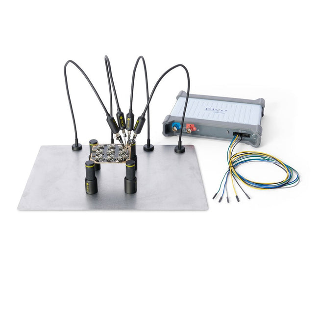
Sensepeek Sensepeek 4003 PCBite Kit incl. 4x SP10 Probe and Test Wires
The minimalist design and the spring loaded test needle makes it possible to simultaneously measure on fine pitch components and nearby signals. The probe is steady but yet flexible made for instant measurements or total hands-free operations together with your multimeter, logic analyzer or preferred tool. The dual pin header connector fits directly on a 2.54 mm (0.100”) connector. The SP10 comes with a powerful magnet in the base, as for all PCBite probes and holders which makes the probe easy to place and reposition. Included 4x PCBite holder 1x Large base plate (A4) 4x PCBite probe with pin tipped test needle 4x Extra crown tipped test needle 1x Set of yellow insulation washers 5x Dupont to dupont test wire 2x Banana to dupont test wire 1x Microfiber cloth Downloads User Guide
€ 152,46
-
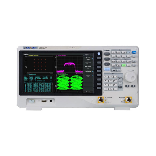
Siglent Siglent SSA3075X Plus Spectrum Analyzer (9 kHz – 7.5 GHz)
The Siglent SSA3075X Plus spectrum analyzer is a powerful and flexible tool for RF signal and network analysis. With a frequency range of 7.5 GHz, the analyzer delivers reliable automatic measurements and multiple modes of operation: spectrum analyzer the base, optional functions include RF power measurement, vector signal modulation analysis, reflection measurement, and EMI test. Applications include broadcast monitoring/evaluation, site surveying, S-parameter measurement, analog/digital modulation analysis, EMI pre-compliance test, research and development, education, production, and maintenance. Features Spectrum Analyzer Frequency Range from 9 kHz to 7.5 GHz –165 dBm/Hz Displayed Average Noise Level (Typ.) –98 dBc/Hz. @ 10 kHz Offset Phase Noise (1 GHz, Typ.) Level Measurement Uncertainty <0.7 dB (Typ.) 1 Hz Minimum Resolution Bandwidth (RBW) Preamplifier (Std.) Tracking Generator (incl. free of charge) Analog and Digital Signal Modulation Analysis Mode (opt.) Reflection Measurement Kit (opt.) EMI Filter and Quasi-Peak Detector Kit (opt.) Advanced Measurement Kit (opt.) 10.1-inch Multi-Touch Screen , Mouse and Keyboard supported Web Browser Remote Control on PC and Mobile Terminals and File Operation Specifications SSA3015X Plus SSA3021X Plus SSA3032X Plus SSA3075X Plus Frequency Range 9 kHz ~ 1.5 GHz 9 kHz ~ 2.1 GHz 9 kHz ~ 3.2 GHz 9 kHz ~ 7.5 GHz Resolution Bandwidth 1 Hz ~ 1 MHz 1 Hz ~ 1 MHz 1 Hz ~ 1 MHz 1 Hz ~ 3 MHz Phase Noise <–99 dBc/Hz <–98 dBc/Hz <–98 dBc/Hz <–98 dBc/Hz Total Amplitude Accuracy <1.2 dB <0.7 dB <0.7 dB <0.7 dB Display Average Noise Level –156 dBm/Hz –161 dBm/Hz –161 dBm/Hz –165 dBm/Hz Included Siglent SSA3075X Plus spectrum analyzer USB cable Power cord Quick start guide Downloads Datasheet Manual Documentation Firmware
€ 7.875,89
-

Elektor Digital Practical Electronics Crash Course (E-book)
Learning circuit design the fun way Welcome to the world of electronics! Getting started in electronics is not as difficult as you may think. Using this book, you will explore and learn the most important electrical and electronics engineering concepts in a fun way by doing various experiments and by simulating circuits. It will teach you electronics practically without getting into complex technical jargon and long calculations. As a result, you will be creating your own projects soon. No prior knowledge of electronics is required, only some basic algebra is used in a few simple calculations. Many tested and working projects and simulations are presented to familiarise yourself with the construction of electronic circuits. Circuit simulation is introduced at an early stage to enable you to experiment with circuits easily without breaking anything. You will learn: The concepts of voltage, current, and power AC and DC Basic lamp circuits with switches Passive components: resistors, capacitors & inductors RC & RCL circuits Electromagnetism Loudspeakers, relays, buzzers, and transformers Active components: diodes & LEDs, bipolar transistors & MOSFETs Transistor-based switching circuits Optocoupler circuits Astable & monostable multivibrators Using the 555 timer IC The operational amplifier Digital logic Advanced examples: amplifiers, oscillators, filters, and sensors Test and measurement tools Microcontrollers: Arduino UNO, ESP32, Raspberry Pi Pico, and Raspberry Pi Reading datasheets and best practices for selecting components EMC & EMI and norms & regulations
€ 32,95
Members: € 29,66
-

Elektor 01-02/2025 (DE)
Diese Ausgabe steht allen GOLD- und GREEN-Mitgliedern auf der ElektorMagazine-Website zum Download bereit! Sie sind noch kein Mitglied? Hier klicken! DIY-SolarakkusÜber den Selbstbau von Energiespeichern für Solaranlagen Solarmodul-SimulatorFür Test und Optimierung von MPP-Trackern und Invertern Der STM32-Edge-KI-WettbewerbEntdecken Sie den neuen STM32N6 und nehmen Sie am Wettbewerb um 5.000 € teil! Erweiterung der BandlückeWarum gibt es so viel Interesse an SiC und GaN? Power-Bank für NotebooksVerlängern Sie das Leben Ihres alten Laptops! Medizinische RoboterÜberwindung technischer und regulatorischer Hürden Frostwächter für ObstpflanzenMit Temperatur-Datenlogger Das analoge DingDer Arduino des Analog-Computings? Sparsames NetzrelaisMit über 90% Leistungsreduzierung Verbesserung der DC-Last ET5410A+Keep cool and be quiet! electronica 2024 im Rückblick Elektromagnetische VerträglichkeitEMV kurz und bündig! Aller Anfang......muss nicht schwer sein: Aktive Filter Verlustleistung reduzieren mit AbleitkondensatorenEin cleverer Einsatz von kapazitiver Reaktanz Preiswerter 12-Bit-Digital-Analog-Wandler MCP4725Mit EEPROM-Feature für sicheres Einschaltverhalten Fnirsi LCR-ST1, die intelligente LCR-SMD-Pinzette Test- und Messlabor mit Raspberry PiDas Wichtigste zuerst: Der ADC Elektronischer LastwiderstandEin Projekt aus der Kiste 2025: Eine Odyssee in die KIEinige Projekte für das neue Jahr Projekt-Update: Modulares DC-Leistungsmessgerät AmpVolt v2.0100 Ampere und mehr! Projekt 2.0 Ethische Transparenz sichtbar gemachtErgebnisse der Umfrage 2024 von Ethics in Electronics Elektor Audio-DSP FX-Prozessor-BoardTeil 2: Anwendungen erstellen
€ 14,90


