Elektor GREEN en GOLD leden kunnen deze uitgave hier downloaden.
Nog geen lid? Klik hier om een lidmaatschap af te sluiten.
De ESP-BLASTEen mini ESP32 raketdrone die ruim 100 km/u vliegt
STM32Cube Innovation-ChallengeDoe mee met je beste STM32C5-ontwerp
Wireless workshop (1)Radiomodules uitgelegd: 433 MHz CC1101 sub-GHz-transceiver
AM-zenderMet sinus- en blokgolfgenerator op Raspberry Pi Pico
AudiotronicaDe vervormingsfactor
CoffeeCallerOmroepsysteem met mesh-netwerk en Zephyr gebaseerde software
Elektor wordt 65Projecten uit voorgaande september- en oktobermaanden
Bluetooth Channel Sounding voor het volgen van objectenAfstandsmeting met centimeterprecisie voor het IoT van de volgende generatie
2026: Een AI-odysseeKwantumcomputing is geen volgende GPU
Om de cloud te beveiligen, is edge-beveiliging nodig
Eerste ervaringen met de HackRF ProPraktische tests met de nieuwe SDR-hardware
Modemupgrade van GPRS/2G naar LTE/4GEen draadloos alarmsysteem als voorbeeld
Lusvormige antenne met RF-bouwstenenDeel 1: Een zelfbouw kortegolfantenne met instelbare richtingsgevoeligheid
Internetradio naar AM-converterMet een ESP32-S3 als zender
Err-lectronics
Mioty, een overzichtFraunhofer's aanpak van LPWAN
WerkbankwijsheidPraktische tips van experts
Walter, de compacte IoT-moduleDeel 2: Toegang tot weer- en datadiensten
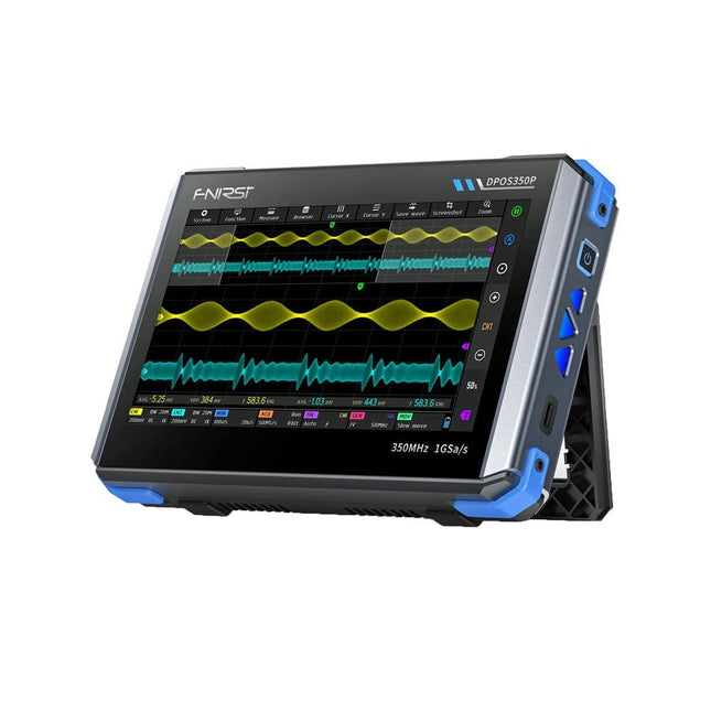
2 Channels • 350 MHz • 1 GSa/s • 50,000 wfm/s • 7 inch Touchscreen
The FNIRSI DPOS350P is a sleek 4-in-1 powerhouse in tablet form! This compact and portable device packs serious functionality: it combines a 2-channel oscilloscope (350 MHz), a signal generator (50 MHz), a frequency response analyzer (50 MHz), and a spectrum analyzer (200 kHz–350 MHz) – all in one unit.
Whether you're in R&D, troubleshooting, or field testing, the DPOS350P delivers the tools you need to measure, generate, analyze, and visualize electronic signals with precision and clarity. Its responsive high-resolution touchscreen and intuitive controls make signal analysis fast, flexible and efficient.
Features
Powerful Multi-Function Integration
350 MHz 2-channel oscilloscope with 1 GSa/s real-time sampling
50 MHz signal generator with 14 standard + custom waveforms
Spectrum analyzer (200 kHz–350 MHz): Perfect for EMI, RF & HF testing
Frequency response analyzer (FRA) up to 50 MHz
High-Performance Waveform Capture
50,000 wfm/s refresh rate for real-time signal clarity
350 MHz bandwidth (single-channel mode)
Detects rare and low-probability anomalies
Crisp Display & Smooth Operation
7" IPS touchscreen (1024 x 600 resolution)
Switch between grayscale and color temperature display
Easy to operate in various test environments
Reliable, Protected & Fast-Charging
High-voltage protection up to 400 V
Fast charging with QC 18 W (full charge in 2 hours)
Built for stable long-term operation
Data Storage & Export
Save up to 500 waveform records + 90 screenshots
USB export for easy reporting and offline analysis
Specifications
General
Display
7 inch (IPS full viewing angle)
Resolution
1024 x 600 pixels
Interaction mode
Capacitive touch screen
Total power consumption
10 W
Power-on configuration
5 presets
Charging
QC 18 W, 12 V/1.5 A (USB-C)
Battery
3.7 V, 8000 mAh lithium battery
Battery life
approx. 3 hours in operation, 5 hours standby
Heat dissipation
Air cooling
Expansion interface
USB data port
Automatic shutdown
15~60 minutes / off
Firmware upgrade
Support .iso image upgrade
Languages
English / Portuguese / Russian / Chinese
Dimensions
190 x 128 x 37 mm
Oscilloscope
Analog channels
2
Analog bandwidth
350 MHz
Rise time
1ns
Real-time sampling rate
1 GSa/s
Memory depth
60 Kpts
Input impedance
1 MΩ / 14PF
Time base range
5ns ~ 50s
Roll time base
50ms ~ 50s
Vertical sensitivity
2 mV ~ 20 V (1X)
Vertical range
16 mV ~ 160 V (1X)
DC accuracy
±2%
Time accuracy
±0.01%
Input coupling
DC / AC
Probe attenuation
1X / 10X / 100X
Hardware bandwidth limit
150M / 20M
High resolution mode
8bit ~ 16bit
Parameter measurements
12 types
Cursor measurement
Time, period, frequency, level, voltage
Trigger detection
Digital trigger
Trigger channel
CH1 / CH2
Trigger mode
Auto / Single / Normal
Trigger edge
Rising edge / Falling edge
Trigger suppression
L1 ~ L3
Trigger level
Manual / automatic 10% ~ 90%
Screenshot storage
90 pictures
Waveform storage
500 groups
Background grid
Display / hide
Waveform movement
Coarse adjustment / fine adjustment
Overvoltage protection
Withstand voltage 400 V
Waveform brightness
Adjustable
Simple FFT display
Yes
Digital fluorescence
Yes
Color temperature display
Yes
X-Y mode
Yes
ZOOM time base
Yes
One-key automatic adjustment
Yes
One-key return to zero
Yes
Data browser
Yes
Signal Generator
Waveform types
14 standard functions + captured waveform
Frequency
0~50 MHz (sine wave only, other waveforms up to 10M/5M/3M)
Amplitude
0~5 VPP
Offset
-2.5 V ~ +2.5V
Duty cycle
0.1~99.9%
Frequency resolution
1 Hz
Amplitude resolution
1 mV
Offset resolution
1 mV
Duty cycle resolution
0.1%
Customizable captured waveform
500 groups
Frequency Response Analyzer (FRA)
Excitation signal frequency
100 Hz ~ 50 MHz
Excitation signal amplitude
0~5 VPP
Excitation signal offset
-2.5V ~ +2.5V
Excitation frequency count
20~500
Cursor measurement
Frequency / gain / phase
Operating mode
Single / cyclic
System calibration
Yes
Spectrum Analyzer
Conversion method
FFT
FFT length
4K ~ 32K
Frequency range
200 KHz ~ 350 MHz
Level range
-60 dBmV ~ +260 dBmV
Cursor measurement
Frequency / amplitude
Marking parameter
Maximum energy harmonic
Waterfall chart
Yes
3D waterfall chart
Yes
Automatic adjustment
Yes
System calibration
Yes
Included
1x FNIRSI DPOS350P Oscilloscope (4-in-1)
2x 350 MHz Probes
1x QC 18 W Fast Charger (EU)
1x USB-C Cable
1x Alligator Clip
1x Storage Bag
1x Manual
Downloads
Manual
Firmware
Arduino Uno est une plaque de développement de microcontrôleur, avec superposition de code source (matériel, EDI et bibliothèques). Arduino est l'une des plus grandes communautés de programmeurs, d'ingénieurs et d'électroniciens, de passionnés et d'étudiants universitaires. Merci pour vos bibliothèques, le programme devient adapté à votre jeune enfant et la rapidité. Les bibliothèques entièrement testées et fonctionnelles facilitent le test des programmes.
Le Raspberry Pi 4, une version récente du système nano-ordonné, est utilisé pour les appareils multimédias, ainsi que pour les applications industrielles, robotiques, domestiques et commerciales. Grâce à la connectivité Wi-Fi et Bluetooth, votre Raspberry Pi 4 est parfait pour la commande et la surveillance à distance via Internet.
Ce livre avec une œuvre de Raspberry Pi 4 et de l'Arduino Uno dans des applications de régulation avec l'algorithme PID. Après avoir examiné la théorie des systèmes de régulation et des systèmes intégrés, l'évaluation des fonctions du projet et les tests de pilotage des systèmes de régulation PID en temps réel. Le timing et la structure des paramètres PID et le timing et la structure des systèmes détaillés et détaillés (schémas fonctionnels, schémas de circuits, algorithmes de régulation PID, liste complète des cartes).
Ces projets s'appuient constamment sur la théorie et les applications des régulateurs PID. C'est un simple modificateur pour d'autres applications. Les projets pour le Raspberry Pi 4 sont adaptables selon les différents modèles de la famille Raspberry Pi.
Le livre couvre les sujets suivants :
Systèmes de régulation et systèmes ouverts et fermés
Capteurs analogiques et numériques
Fonctions de transfert et de système en continu
Enregistrements temporels des systèmes du 1er et du 2ème ordre
Systèmes discrets (nombres)
Les régulateurs PID sont des systèmes à température continue
Numéros PID des régulateurs
Régulation de température selon Raspberry Pi et Arduino Uno
Régulation de température PID à l'aide de Raspberry Pi et Arduino Uno
Pilotage continu de moteurs utilisant Raspberry Pi et Arduino Uno
Régulation PID pour surveiller le niveau du Raspberry Pi et de l'Arduino Uno
Régulation PID pour piloter une LED avec Raspberry Pi et Arduino Uno
Ungefähr seit dem Jahr 2000 bieten Fahrzeuge Zugriff auf Diagnosedaten, Messwerte und erkannte Fehler, die mit preiswerten Geräten ausgelesen werden können. Die Daten helfen Ihnen nicht nur bei der Fehlersuche, sondern auch beim Gebrauchtwagenkauf oder dem reibungslosen Bestehen der nächsten Hauptuntersuchung. Die zunehmende Komplexität und Vernetzung der integrierten elektronischen Kontroll- und Steuerungssysteme im Fahrzeug erfordert vom Kfz-Mechatroniker sowie dem ambitionierten Selbstschrauber ein tiefgreifendes Verständnis der Thematik.
Dieses Sachbuch bietet Ihnen eine umfassende Einführung zu den in Kraftfahrzeugen vorhandenen genormten On-Board-Diagnosemöglichkeiten (OBD II), deren Ursprünge, Stand der Entwicklung, Protokollaufbau und Anwendung. Das Buch richtet sich an eine breite Leserschaft, die selbst die Möglichkeiten nutzen will, um nicht mehr auf kostspielige Werkstattbesuche angewiesen zu sein oder sich für eine Eigenentwicklung von Diagnosesystemen und eine praxisnahe Beschreibung der Protokolle interessiert.
Durch den Einsatz günstiger Diagnoseadapter (ELM 327 etc.) können Sie sich auf dem Smartphone Live-Daten anzeigen lassen und Cockpitinstrumente nachrüsten oder eigene Anwendungssoftware für verschiedene Systeme erstellen.
Themenauswahl
Historische Entwicklung der Diagnosemöglichkeiten und Standards
Funktionsumfang von OBD II mit allen zehn Diagnosemodi und Readinesscode
World Wide Harmonized OBD (WWH-OBD) und HD OBD (Heavy Duty: Nutzfahrzeuge)
Anschlüsse gemäß SAE J1962, SAE J1939, SAE J1708 und DoIP (ISO 13400)
Protokollaufbau nach SAE J1850, ISO 9141, ISO 14230 und CAN
Übersicht gängiger Diagnoselösungen für Hobbyanwender
Eigenbau von Diagnosesystemen mit Arduino und Raspberry Pi
Alle Parameter Identifier (Messwerte) für OBD II
Umfangreiche Liste der Fehlercodes zum Nachschlagen
electronica Fast Forward Start- & Scale-Up AwardsLes préparatifs s?accélèrent?!
Bluetooth Low Energy avec ESP32-C3 et ESP32Vous n?avez pas toujours besoin de choisir le wifi?!
Renifleur BLEReconfiguration du dongle USB nRF52840 MDK de makerdiary
Cube magique de LED RGBcircuit avec un RP2040
Marche/arrêt automatique pour le compresseur de pâte à souder
Contenu vidéo d?ElektorLivestreams, webinaires et cours pour les ingénieurs et les fabricants professionnels
Électrification d?un véloUtilisation d?un kit de modification de vélo électrique
Démarer en électroniqueMultiplication de tensions
Sur le vifTransmutations
Teensy 4.0 ? comment cette carte peut-elle être aussi rapide ?Ou: La vitesse, ce n'est pas sorcier !
Simulation d?amplificateur de puissance audio avec TINA«?simuler avant de construire?»
Développer et utiliser vos n?uds LoRaWAN pour l'Internet des Objets (IdO)Exemple de chapitre : Modules LoRaWAN Dragino LHT65, LDS01 et LDS02
Projet 2.0Corrections, mises à jour et courriers des lecteurs
5G pour mon propre exploitMaîtrise totale du déploiement de la 5G avec les réseaux cellulaires privés
Infographics
Les meilleurs conseils pour développer une interface WiFiComment mon appareil apprend-il à transmettre ?
Horloge Tour du Rhin Mod 2
Analyseur de spectre audio avec dekatronsUne nouvelle façon d'utiliser les tubes rétro
Envoi de données à TelegramAvec un ESP32 et quelques composants
Filtre coupe-bande de Fliege pour les mesures audioFaites de meilleures mesures avec un filtre coupe-bande
Démontage d?un CO2-mètrePeut-on le bidouiller pour vos projets??
Tout mis ensembleLe transistor unijonction programmable expliqué
Écran tactile rond pour Raspberry PiL?HyperPixel 2.1 Round de Pimoroni
Télémesure avec détection des pertes de connexionGrâce aux modules nRF24L01+
Récepteur FM numérique avec Arduino et TEA5767Restez à l?écoute avec un Arduino Nano
Convertir une interface OLED de SPI vers I²C
HomeLab ToursUn passe-temps ne prend pas sa retraite
Une décennie d?éthique en électroniqueLe regard de Tessel Renzenbrink sur la société numérique.
HexadokuThe Original Elektorized Sudoku
Projekte mit Arduino Uno und Raspberry Pi
In diesem Buch werden Anwendungen von Arduino Uno und Raspberry Pi 4 in praxisnahen Projekten auf Basis von CAN-Bus detailliert beschrieben. Durch den Einsatz von entweder Arduino Uno oder Raspberry Pi in Verbindung mit handelsüblichen CAN-Bus-Schnittstellenmodulen werden die Entwicklung, Fehlersuche und Fehlerbeseitigung sowie die Überprüfung von Projekten auf CAN-Bus-Basis erheblich erleichtert.
Dieses Buch richtet sich an jeden, der mehr über den CAN-Bus lernen möchte und mit den Grundlagen der Elektronik vertraut ist. Hilfreich ist auch Erfahrung mit den Programmiersprachen C und Python sowie mit der Programmierung von Arduino Uno unter Verwendung seiner IDE und von Raspberry Pi zu haben.
Das Buch ist eine nützliche Informationsquelle und ein Nachschlagewerk für jeden, der Antworten auf eine oder mehrere der folgenden Fragen sucht:
Welche Bussysteme stehen für die Automobilindustrie zur Verfügung?
Was sind die Grundprinzipien des CAN-Bus?
Welche Arten von Frames (oder Datenpaketen) stehen in einem CAN-Bussystem zur Verfügung?
Wie können Fehler in einem CAN-Bussystem erkannt werden, und wie zuverlässig ist ein CAN-Bussystem?
Welche Arten von CAN-Bus-Controllern gibt es?
Welches sind die Funktionsprinzipien des MCP2515 CAN-Bus-Controllers?
Wie kann ich ein CAN-Bus-Projekt mit Arduino Uno realisieren?
Wie kann ich Arduino oder Raspberry Pi CAN-Bus-Projekte mit 2 und 3 Knoten erstellen?
Wie kann ich die Daten auf dem CAN-Bus analysieren?
Wie kann ich ein CAN-Bus-Projekt mit Raspberry Pi ausführen?
From Simple Ciphers to Secure Systems
Understanding how to apply cryptography on modern microcontrollers is essential for building secure, reliable, and trustworthy systems. This book explains cryptography in the context of embedded hardware, from classical ciphers that illustrate core principles to modern techniques such as AES for practical high-security applications.
By combining mathematical theory with real-world microcontroller implementations, readers learn not only how cryptography works, but also how to implement it effectively on systems with limited processing power and memory. The book is intended for students starting out in cryptography, hobbyists securing personal projects, and engineers looking for a structured guide to embedded security.
The book covers these key topics in applied cryptography:
Classical ciphers on Arduino Uno and Raspberry Pi Pico, with full programs: Spartan Scytale, Hebrew Atbash, Caesar, ROT13, Alberti Disk, Vigenère, Affine, Polybius, Playfair, Beaufort, Ottoman Codebook, and One-Time Pad.
Hacking classical ciphers using microcontrollers, with examples.
Pseudo-random (PRNG) and true random number generation (TRNG) on microcontrollers.
Symmetric-key cryptography with full programs: DES and AES-128/256.
Memory and speed constraints of cryptography on microcontrollers.
Asymmetric cryptography: public/private keys, digital signatures, key distribution and derivation (KDF), RSA, and SHA-256 implementations.
A complete secure communication program using RSA and AES-256.
A glossary of commonly used cryptography terms.
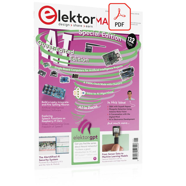
Elektor GREEN and GOLD members can download their digital edition here.
Not a member yet? Click here.
The AlertAlfred AI Security SystemPowered by a Raspberry Pi 5 and the Hailo 8L Module
AI in Electronics DevelopmentAn Update After Only One Year
Intro to AI AlgorithmsPrompt: Which Algorithms Implement Each AI Tool?
Single-Board Computers for Artificial Intelligence ProjectsBackground and Overview
From Sensor Data to Machine Learning ModelsGesture Detection with an Accelerometer and Edge Impulse
Build a Leaky Integrate-and-Fire Spiking NeuronArtificial Intelligence Without Software
ChatGPT for Electronic DesignDoes GPT-4o Do It Any Better?
Bringing AI to the Edge with ESP32-P4
Exploring Speech Functions on Raspberry Pi ZeroWhen Overclocking Gives Freedom of Speech
The Growing Role of Edge AIA Trend Shaping the Future
Unlocking the Power of Edge AIA Conversation with François de Rochebouët of STMicroelectronics
A VHDL Clock Made with ChatGPT
AI’s Real ImpactSayash Kapoor on “AI Snake Oil” and More
The Latest Stuff From BeagleBoardBeagleY-AI, BeagleV-Fire, BeagleMod, BeaglePlay and BeagleConnect Freedom
Mosquito Detection Using Open Datasets and Arduino Nicla Vision
AI Today and Tomorrow: Insights from Espressif, Arduino, and SparkFun
Artificial Intelligence Timeline
BeagleY-AIThe Latest SBC for AI Applications
AI in FocusPerspectives from the Elektor Community
Machine Vision with OpenMVCreate a Soda Can Detector
A Conversation with the Digital MindChatGPT vs Gemini
Skilling Me Softly with This Bot?Is the AI Revolution in the Electronic Field Failing Due to a Lack of Social Precision?
High-Performance LoRa Communication Device
The Elecrow ThinkNode M5 is a compact, portable LoRa communication device designed for off-grid messaging, location sharing, and outdoor use. Powered by an ESP32-S3 processor and an SX1262 LoRa chip, it comes pre-installed with Meshtastic firmware and can be configured conveniently via Bluetooth using the official Meshtastic app.
The integrated multi-GNSS module supports GPS, GLONASS, BeiDou, and QZSS for reliable positioning and location sharing. Messages and device information are displayed on the energy-efficient 1.54-inch e-paper screen, while the built-in 1,200 mAh rechargeable battery enables extended mobile operation.
With its integrated LoRa antenna, compact housing, RTC, and support for both Meshtastic and MeshCore firmware, the ThinkNode M5 is a practical communication solution for hiking, camping, remote locations, and emergency situations where conventional mobile networks are unavailable.
Features
LoRa communication
Multi-GNSS positioning
1,200 mAh rechargeable battery
1.54-inch e-paper display
Built-in RTC
Compatible with MeshCore
Compatible with Meshtastic
Specifications
Main Processor (ESP32-S3)
CPU/SoC
Xtensa 32-bit LX7 dual-core processor, clocked at up to 240 MHz
System Memory
512 KB SRAM, 8 MB PSRAM
Storage
4 MB Flash, 384 KB ROM
Firmware
Meshtastic firmware is fully compatible, and the signal is transmitted in LoRa mode
EPD (Electronic Paper Display)
Display Size
1.54 inch EPD (monochrome Ink screen)
Display Materials
E-lnk (Electronic Ink)
Resolution
200 x 200
Driver Chip
SSD1681 (via SPI or I²C interface)
Global Fresh Time
2s
Wireless Communication
Bluetooth
Bluetooth Low Energy and Bluetooth 5.0 (phone configuration)
LoRa
SX1262 LoRa Module, EU 868 MHz(external antenna)
Hardware
Interfaces
USB-C, RP-SMA
Function
GPS Location (GPS, GLONASS, BeiDou, QZSS), EPD Display, RTC, USB 2.0, PMU power management (built-in 1200 mAh lithium battery), buzzer, etc.
Button
Knob Switch, Function Button, Page Turn Button, GPS Switch, Reset Button
LED Indicator
Power supply, GPS/LoRa indication
Others
Power Input
5 V/1 A, supports USB or lithium battery power supply
Power consumption
The maximum working current is about 340 mA (CPU + LoRa module), and the low power consumption is about 34 uA
Operating Temperature
-10~50°C
Storage Temperature
-20~60°C
Relative humidity
10-95%, @ 40°C (non-condensing)
Enclosure
ABS Plastic
Dimensions
82 x 51.6 x 26.3 mm
Weight
81 g
Included
1x Elecrow ThinkNode M5
1x LoRa antenna
1x USB-C cable
1x Manual
Downloads
Manual
Mit dem Elektor Arduino Nano Trainingsboard (MCCAB) eigene Projekte realisieren
Der Mikrocontroller ist das wohl faszinierendste Teilgebiet der Elektronik, denn aufgrund der Vielzahl von Funktionen, die er auf seinem Chip vereinigt, ist er für den Entwickler ein universelles Multi-Tool zur Realisierung seiner Projekte. Praktisch jedes Gerät des täglichen Gebrauchs wird heute von einem Mikrocontroller gesteuert. Für einen elektronischen Laien blieb es aufgrund der Komplexität bisher allerdings ein Wunschtraum, eigene Ideen mit einem Mikrocontroller zu realisieren. Das Arduino-Konzept hat den Einsatz von Mikrocontrollern weitgehend vereinfacht, sodass jetzt auch Laien eigene Elektronik-Ideen mit einem Mikrocontroller verwirklichen können.
Buch & Hardware im Bundle: 'Learning by Doing'
Dieses im Bundle mitgelieferte Buch (im großen A4-Format) zeigt, wie man auch ohne große Erfahrung in Elektronik und Programmiersprachen eigene Projekte mit einem Mikrocontroller realisieren kann. Es ist ein Mikrocontroller-Praxiskurs für Einsteiger, denn nach einem Überblick über die Interna des Mikrocontrollers und einer Einführung in die Programmiersprache C liegt der Schwerpunkt des Kurses auf den praktischen Übungen. Der Leser eignet sich die erforderlichen Kenntnisse durch 'Learning by Doing' an: in dem umfangreichen Praxisteil mit 12 Projekten und 46 Übungen wird das im vorderen Teil des Buches Gelernte mit vielen Beispielen unterlegt. Die Übungen sind dabei so aufgebaut, dass der Bearbeiter eine Aufgabenstellung erhält, die er mit seinem im Theorieteil des Buches aufgebauten Wissen löst. Für jede Übung gibt es anschließend eine ausführlich erklärte und kommentierte Musterlösung, die dem Bearbeiter bei Problemen weiterhilft und die er mit seiner eigenen Lösung vergleichen kann.
Arduino IDE
In der Arduino IDE, einer Software-Entwicklungsumgebung, die kostenlos auf den eigenen PC heruntergeladen werden kann und die das gesamte Softwarepaket enthält, das für ein eigenes Mikrocontroller-Projekt benötigt wird, schreibt der Bearbeiter mit dem Editor der IDE seine Programme („Apps“) in der Programmiersprache C. Der in die Arduino IDE integrierte Compiler übersetzt sie in die Bits und Bytes, die der Mikrocontroller versteht und die dann über ein USB-Kabel in den Speicher des Mikrocontrollers auf dem Elektor Arduino Nano Trainingsboard (MCCAB) geladen werden.
Externe Sensoren, Motoren oder Baugruppen abfragen oder steuern
Das Elektor Arduino Nano Trainingsboard (MCCAB) enthält neben einem Mikrocontrollermodul Arduino Nano alle für die Übungen benötigten Bauteile wie Leuchtdioden, Schalter, Taster, akustische Signalgeber usw. Auch externe Sensoren, Motoren oder Baugruppen können mit diesem Mikrocontroller-Übungssystem abgefragt oder gesteuert werden.
Technische Daten (Arduino Nano Trainingsboard MCCAB)
Stromversorgung
Über die USB-Verbindung des zur Erstellung der Programme sowieso angeschlossenen PCs oder ein externes Netzteil (nicht im Lieferumfang enthalten)
Betriebsspannung
+5 Vcc
Eingangsspannung
Alle Eingänge
0 V bis +5 V
VX1 und VX2
+8 V bis +12 V (nur bei Verwendung eines externen Netzteils)
Mikrocontrollermodul
Arduino Nano
Hardwareperipherie
LCD
2x16 Zeichen
Potenziometer P1 & P2
JP3: Auswahl der Betriebsspannung von P1 & P2
Verteiler
SV4: Verteiler für die BetriebsspannungenSV5, SV6: Verteiler für die Ein-/Ausgänge des Mikrocontrollers
Schalter und Taster
RESET-Taster auf dem Arduino Nano-Modul6x Tastschalter K1 … K66x Schiebeschalter S1 … S6JP2: Verbindung der Schalter mit den Eingängen des Mikrocontrollers
Summer
Piezo-Summer Buzzer1 mit Steckbrücke auf JP6
Leuchtanzeigen
LED L auf dem Arduino Nano-Modul, verbunden mit GPIO D1311x LED: Zustandsanzeige für die Ein-/AusgängeJP6: Verbindung der LEDs LD10 … LD20 mit den GPIOs D2 … D12
Serielle SchnittstellenSPI & I²C
JP4: Auswahl des Signals an Pin X der SPI-Steckerleiste SV12SV9 bis SV12: SPI-Interface (3,3 V/5 V) bzw. I²C-Interface
Schaltausgang für externe Geräte
SV1, SV7: Schaltausgang (maximal +24 V/160 mA, extern zugeführt)SV2: 2x13 Pins zum Anschluss externer Module
3x3 LED-Matrix (9 rote LEDs)
SV3: Spalten der 3x3 LED-Matrix (Ausgänge D6 … D8)JP1: Verbindung der Reihen mit den GPIOs D3 … D5
Software
Library MCCABLib
Steuerung der Hardware-Komponenten (Schalter, Taster, Leuchtdioden, 3x3 LED-Matrix, Summer) auf dem MCCAB Trainingsboard
Betriebstemperatur
bis +40 °C
Abmessungen
100 x 100 x 20 mm
Technische Daten (Arduino Nano)
Mikrocontroller
ATmega328P
Architektur
AVR
Betriebsspannung
5 V
Flashspeicher
32 KB, davon 2 KB vom Bootloader belegt
SRAM
2 KB
Taktfrequenz
16 MHz
Analoge IN-Pins
8
EEPROM
1 KB
DC-Strom pro I/O-Pin
40 mA an einem I/O-Pin, insgesamt maximal 200 mA an allen Pins gemeinsam
Eingangsspannung
7-12 V
Digitale I/O-Pins
22 (6 davon sind PWM-fähig)
PWM-Ausgänge
6
Stromverbrauch
19 mA
Abmessungen
18 x 45 mm
Gewicht
7 g
Lieferumfang
Elektor Arduino Nano MCCAB Trainingsboard
Arduino Nano
Buch: Mikrocontroller-Praxiskurs für Arduino-Einsteiger
DIE NEURONEN IN NEURONALEN NETZWERKEN VERSTEHENTeil 1. Künstliche Neuronen
EMV-VOR-KONFORMITÄTSTESTER FÜR IHR PROJEKT MIT DC-VERSORGUNGTeil 1: Was ist eine Netznachbildung?
ELEKTRONISCHE LAST FÜR DC UND ACBis zu 400 V und 10 A
ALLER ANFANG …ist gar nicht schwer!
NVIDIA JETSON NANO - BILDVERARBEITUNG FÜR EINSTEIGERTeil 1: Hard- und Software im Überblick
NETZTRANSFORMATOREN AUS DER NÄHE BETRACHTETWie verhalten sie sich beim Ein- und Ausschalten?
PICAN 3 - YES WE CAN!CAN-Zusatzboard für Raspberry Pi 4
BALKONKRAFTWERKSelbst installiert = schnell amortisiert!
FOTOGRAFIEREN UND VIDEO-STREAMING MIT DEM RASPBERRY PI 4Die High-Quality-Kamera des Raspberry Pi in der Praxis
VERWENDUNG VON DISPLAYS IN RASPBERRY-PI-PROJEKTENBeispiel-Kapitel: Organische Leuchtdioden-Displays (OLED)
PARALLAX PROPELLER 2Teil 4: Senden von Strings
60 JAHRE ELEKTOR: SEPTEMBER-RENAISSANCEDer Plan, der Plan, ein leerer Wahn ...
ZUTRITT FÜR UNBEFUGE VERBOTEN ERWÜNSCHTIn Friesland, wo die Röhren blühen ...
HYBRIDE SCHALTUNGENBemerkenswerte Bauteile
KOMPASSROSE MIT DEM GY-271Oder, warum man mit dem Handy Achten gehen muss…
KENNEN SIE IHREN FUSSABDRUCKBerechnen Sie die CO2-Bilanz Ihrer Elektronik
ESP32-VERBUNDENES THERMOSTATLagern Sie Ihren Wein bei der richtigen Temperatur!
MAGNETISCHE LEVITATION DIE DIGITALE ARTEin ESP32 Pico ersetzt den analogen Komparator
ULTIMATE ARDUINO UNO HARDWARE MANUALEin beispielhaftes Kapitel: Bootloader für den Haupt-Mikrocontroller
MICROPYTHON FÜR DEN ESP32 UND CO.Teil 2. Matrix-Displays einfach ansteuern
MADMACHINE SWIFTIO-KARTEModerne Sprache trifft moderne Hardware
AUS DEM LEBEN GEGRIFFENEine elektronische On/Off-Beziehung
HEXADOKUSudoku für Elektroniker