
Search results for "elektor or special or arduino or shields or en"
-
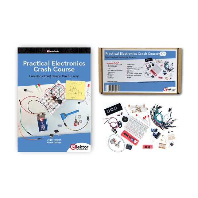
Elektor Bundles Practical Electronics Crash Course (Bundle)
Getting started in electronics is not as difficult as you may think. With this bundle (book + kit of parts), you can explore and learn the most important electrical and electronics engineering concepts in a fun way by doing various experiments. You will learn electronics practically without getting into complex technical jargon and long calculations. As a result, you will be creating your own projects soon. This kit contains the components required to build most of the detailed examples of the book on a breadboard and try them out for real. The kit can, of course, also be used without the book for building other circuits and doing your own experiments. Kit contents 1x 39 Ω, 1 W resistor 1x 47 Ω resistor 1x 180 Ω resistor 1x 330 Ω resistor 3x 1 kΩ resistor 1x 2.2 kΩ resistor 1x 3.9 kΩ resistor 1x 6.8 kΩ resistor 1x 10 kΩ resistor 1x 15 kΩ resistor 1x 22 kΩ resistor 1x 33 kΩ resistor 1x 47 kΩ resistor 1x 56 kΩ resistor 1x 82 kΩ resistor 1x 120 kΩ resistor 1x 680 kΩ resistor 2x 100 kΩ resistor 1x 10 kΩ trimmer 1x 10 kΩ linear potentiometer 1x 100 kΩ linear potentiometer 1x LDR 1x 1 nF ceramic capacitor 2x 10 nF ceramic capacitor 1x 100 nF ceramic capacitor 1x 1 µF, 25 V aluminium electrolytic capacitor 2x 10 µF, 25 V aluminium electrolytic capacitor 1x 100 µF, 25 V aluminium electrolytic capacitor 1x 470 µF, 25 V aluminium electrolytic capacitor 1x 1000 µF, 25 V aluminium electrolytic capacitor 1x RGB LED, Common-Cathode (CC) 1x 1N4148 small signal diode 1x 1N4733A 5.1 V, 1 W Zener diode 3x LED, red 2x BC337 NPN transistor 1x IRFZ44N N-channel MOSFET 2x NE555 timer 1x LM393 comparator 1x 74HCT08 quad AND gate 3x Tactile switch 2x SPDT switch 1x Relay, SPDT, 9 VDC 1x Active buzzer 1x Passive buzzer 50 cm Solid wire, 16 AWG, unjacketed 2x PP3 9 V battery clip 1x Breadboard 20x Jumper wire This bundle contains: Practical Electronics Crash Course Kit (valued at: €45) Book: Practical Electronics Crash Course (normal price: €45)
€ 89,95€ 69,95Best Price
-

Elektor Digital Build Your Own Software-Defined Radio (E-book)
Practical Guide to Modular RF Design Build Your Own Software-Defined Radio combines RF circuitry with hardware programming and PC-based signal processing. The e-book presents a modular approach to building a complete SDR system using RF Bricks – from the mechanical framework and RF modules to measurement tools, PC software, and FPGA implementations. Practical explanations guide readers through real signal paths, construction steps, and measurement routines, linking hardware and software into a flexible SDR platform. Key topics include: Mechanical setup: RF Brick template, chassis, and 19-inch module carrier Bridges: USB isolator, I²C level shifter, I²C power switch, and practical examples Signal-chain design with RF Bricks: antennas, band filters, NanoVNA work, preamplifiers, PLLs, demodulators, direct-conversion chains, multiband options, and narrowband bricks RF measurement Bricks: single- and dual-tone sources, NPR methods, noise generators, notch filters, broadband amplifiers, and impedance bridges Useful accessories: ATU-100 tuner, X-Phase QRM eliminator, and firmware notes PC host software: SoapyAudio adjustments, GQRX, SDR++, and added functionality GnuRadio elements: control blocks, SSB demodulation, GUI components, messaging, and filter handling FPGA-based SDR: VHDL, toolchains, ADC/DAC blocks, oversampling, and a complete SSB/CW signal chain With its modular structure and detailed working examples, this e-book offers a practical path to building and extending modern SDR systems. Downloads Software
€ 32,95
Members: € 29,66
-

Elektor Digital 50 PIC Microcontroller projecten (E-book)
Dit boek bevat 50 leuke en spannende projecten met PIC microcontrollers zoals een laser alarm, USB plaagmuis, eierwekker, jongerenverjager, geluidsschakelaar, capacitieve vloeistofniveau meting, 'vinger in het water' sensor, bewaking van een ruimte met een camera, 220 volt lichtdimmer, pratende microcontroller en nog veel meer. Er komen talloze technieken aan de orde zoals relais, wisselstroomregeling (ook 220 volt), I2C, SPI, RS232, USB, puls breedte modulatie, rotary encoder, interrupts, infrarood, analoog-digitaal conversie (en andersom), 7-segment display en zelfs CAN bus. U kunt dit boek gebruiken om de verschillende projecten na te bouwen en daarna in de praktijk te brengen. Door de duidelijke uitleg, schema's en zelfs foto's van de opstelling is het nabouwen een leuke bezigheid. Bij ieder project wordt uitgelegd waarom het juist op die manier is uitgevoerd, en wordt kort de theorie behandeld. U kunt dit boek dus gebruiken als studieboek, of als basis voor grotere en ingewikkeldere projecten. Alle schakelingen zijn op een steekbord uitgevoerd zodat uitbreiden en aanpassen gemakkelijk is. De drie PIC microcontrollers die in dit boek gebruikt worden, zijn de 16f877A, 18f4455 en 18f4685. Daarnaast komt aan de orde hoe u de programma's van de ene naar de andere microcontroller kunt overzetten (er worden 15 types ondersteund) inclusief twee praktijkvoorbeelden. Alle benodigde software kunt u gratis downloaden. Dat geldt ook voor de open source programmeertaal JAL. Deze krachtige maar toch eenvoudig te leren taal wordt zowel door hobbyisten als professionals gebruikt. Dit boek is ook goed te gebruiken als naslagwerk. U kunt er de uitleg van alle opdrachten van de programmeertaal JAL in terugvinden, en tevens van de gebruikte uitbreidingsbibliotheken. Via de index vindt u gemakkelijk projecten die als voorbeeld kunnen dienen voor de belangrijkste JAL opdrachten. Zelfs wanneer u alle projecten een keer gemaakt hebt, zal dit boek nog lang een plekje naast uw PC behouden.
€ 29,95
Members: € 26,96
-

Elektor Digital Elektor 09-10/2021 (PDF)
DIE NEURONEN IN NEURONALEN NETZWERKEN VERSTEHENTeil 1. Künstliche Neuronen EMV-VOR-KONFORMITÄTSTESTER FÜR IHR PROJEKT MIT DC-VERSORGUNGTeil 1: Was ist eine Netznachbildung? ELEKTRONISCHE LAST FÜR DC UND ACBis zu 400 V und 10 A ALLER ANFANG …ist gar nicht schwer! NVIDIA JETSON NANO - BILDVERARBEITUNG FÜR EINSTEIGERTeil 1: Hard- und Software im Überblick NETZTRANSFORMATOREN AUS DER NÄHE BETRACHTETWie verhalten sie sich beim Ein- und Ausschalten? PICAN 3 - YES WE CAN!CAN-Zusatzboard für Raspberry Pi 4 BALKONKRAFTWERKSelbst installiert = schnell amortisiert! FOTOGRAFIEREN UND VIDEO-STREAMING MIT DEM RASPBERRY PI 4Die High-Quality-Kamera des Raspberry Pi in der Praxis VERWENDUNG VON DISPLAYS IN RASPBERRY-PI-PROJEKTENBeispiel-Kapitel: Organische Leuchtdioden-Displays (OLED) PARALLAX PROPELLER 2Teil 4: Senden von Strings 60 JAHRE ELEKTOR: SEPTEMBER-RENAISSANCEDer Plan, der Plan, ein leerer Wahn ... ZUTRITT FÜR UNBEFUGE VERBOTEN ERWÜNSCHTIn Friesland, wo die Röhren blühen ... HYBRIDE SCHALTUNGENBemerkenswerte Bauteile KOMPASSROSE MIT DEM GY-271Oder, warum man mit dem Handy Achten gehen muss… KENNEN SIE IHREN FUSSABDRUCKBerechnen Sie die CO2-Bilanz Ihrer Elektronik ESP32-VERBUNDENES THERMOSTATLagern Sie Ihren Wein bei der richtigen Temperatur! MAGNETISCHE LEVITATION DIE DIGITALE ARTEin ESP32 Pico ersetzt den analogen Komparator ULTIMATE ARDUINO UNO HARDWARE MANUALEin beispielhaftes Kapitel: Bootloader für den Haupt-Mikrocontroller MICROPYTHON FÜR DEN ESP32 UND CO.Teil 2. Matrix-Displays einfach ansteuern MADMACHINE SWIFTIO-KARTEModerne Sprache trifft moderne Hardware AUS DEM LEBEN GEGRIFFENEine elektronische On/Off-Beziehung HEXADOKUSudoku für Elektroniker
€ 11,90
-

Elektor Labs Elektor Low-Noise Lab Power Supply
The Elektor Low-Noise Lab Power Supply is a fully analogue, adjustable, medium-power symmetrical bench supply that contains no switching or digital components. It provides an output voltage adjustable between 0 V and ±22 V, and an output current adjustable from 0 A to 1 A. Because it avoids any form of switching circuitry, the design delivers extremely low noise. To display both output voltages and currents, four miniature moving-coil panel meters are used. Most modern laboratory power supplies and AC adapters employ switch-mode techniques. Even the best examples inevitably exhibit high-frequency ripple and other switching artefacts on their output, which can interfere with the testing of sensitive analogue circuits and disturb low-level measurements. To overcome this, the concept here is a completely analogue power supply. Although less efficient than its switch-mode counterparts, the reduced efficiency is of little importance for test-bench use and ensures cleaner, more reliable measurement results. Because many analogue circuits require a symmetrical supply, this design delivers positive and negative output voltages of equal magnitude. A small amount of adjustment is available to compensate for any imbalance. Naturally, a variable current-limit function is also included. The kit includes the components required to build the power supply, except for the transformers. Specifications Output Voltage 0…+22 V, 0, −22 V Output Current 0…+1 A, 0…−1 A Noise −85 dBV, (at 0.95 A/20 V, B = 22 kHz) −84 dBV (at 0.95 A/20 V, B > 500 kHz) Ripple 50 µVRMS (at 950 mA/20 V, B = 22 kHz, mainly 100 Hz component) Included 3x PCBs: Regulator (PCB-1), Mains Filter (PCB-2) and Transformer (PCB-3) All the components except the AC transformers 4x moving-coil meters Additional parts for wiring (wires, banana sockets, IEC Power entry module, etc.) Not included The three AC transformers An enclosure Parts List For the Regulator PCB (240386-1) Resistors (250 mW, 1%) R1 = 12 Ω R2, R8, R37, R62 = 1 MΩ R3, R7, R10, R13, R17, R20, R22, R30, R35, R42, R45, R47, R55, R60 = 100 Ω, 600 mW R4, R5 = 4.7 kΩ R6 = 100 kΩ R9, R12, R14, R36, R38, R39, R61, R63, R66, R72, R78, R79 = 10.0 kΩ, 600 mW R11 = 9.76 kΩ, 600 mW R15, R40 = 44.2 kΩ, 600 mW R16, R41, R77 = 1 kΩ R18, R43 = 1.5 kΩ, 1 W, 5% R19, R44 = 470 Ω, 1 W, 5% R21, R46 = 330 Ω, 600 mW R23, R24, R48, R49 = 1.0 Ω, 1 W R25, R50 = 1 kΩ, 1 W, 5% R26, R28, R51, R53 = 1.000 kΩ 0.1%, 15 ppm/C R27, R29, R52, R54 = 10.00 kΩ 0.1%, 15 ppm/C R31, R56 = 1.2 kΩ, 1 W, 5% R32, R57 = 47 kΩ R33, R58 = 270 Ω R34, R59 = 27 kΩ R64, R69 = 12.0 kΩ R65 = 3.0 kΩ, 600 mW R67, R80 = 470 Ω, 600 mW R68, R70 = 6.8 kΩ, 600 mW R71 = 30.0 kΩ,, 600 mW R73, R74, R75, R76 = 10 MΩ P1, P2, P3 = 10 kΩ, 200 mW, 20%, potentiometer, 1 turns, single, lin., panel mount P4, P5 = 500 Ω, 500 mW, 10%, trimmer, 25 turns, 3296Y-1-501LF Bourns P6, P7 = 10 kΩ, 500 mW, 10%, trimmer, 25 turns, 3296Y-1-501LF Bourns Capacitors C1 = 100 nF, 50 V, 10%, ceramic X7R, LS 5 mm C2, C3, C6, C7, C30 = 10 µF, 63V, 20%, LS 2.5 mm, 3000hours@105°C C4, C5, C8, C9, C13, C14, C18, C19, C23, C24, C28, C29, C31, C32, C38, C39 = 100 nF, 250 V, 10%, PET, LS 7.5 mm C10, C20 = 47 nF, 100 V, 5%, PET, LS 5 mm C11, C21 = 10 nF, 100 V, 5%, PET, LS 5 mm C12, C22 = 220 µF, 35 V, 20%, 0.024 Ω, LS2.5/3.5 mm, Ir 3.4 A, 2000hours@125°C, polymer C15, C25 = 120 µF, 50 V, 20%, ESR 0.02 Ω, Diam. 10 mm max., LS 5 mm C16, C26 = 15 nF, 100 V, 5%, PET, LS 5 mm C17, C27 = 47 nF, 100 V, 5%, PET, LS 5 mm C33, C34 = 22 µF, 50 V, 20%, LS 2 mm, 10000 hours @ 105°C C35, C36, C44, C45 = 1 µF, 100 V, 10%, LS 5 mm, ceramic X7R C37 = 100 uF, 50 V, 20%. LS 3.5 mm C40, C41, C42, C43, C46, C47, C48, C49 = 1000 µF, 50 V, 20%, LS 5/7.5 mm, Ir 3.32 A, 10000hours@105°C, D 16 mm C50, C51, C52, C53 = 47 nF, 100 V, 10%, ceramic X7R, LS 5 mm Inductors L1, L2 = 4.7 µH, 3.2 A, 0.033 Ω, LS 5 mm, RLB0914-4R7ML Bourns L3 = Commom mode choke, 14.5 mH, 3 A, SSRH24NH-30145 Kemet Semiconductors D1, D2, D3, D4, D5, D9, D10, D11, D15 = BAT85, DO-34 D6, D7, D12, D13 = SR560, DO-201AD D8, D14, D16 = 1N4148, DO-35 D17 = Zenerdiode, 5.6 V, 0.5 W, DO-41 D18, D19 = 1N4004, DO-41 D20, D21 D22, D23 = V30100CI-M3/P, dual common cathode, TO-220 D24 = Zener diode, 30 V, 1 W, DO-41 LED1, LED2 = LED, red, T-1 (3 mm) LED3, LED4 = LED, green, T-1 (3 mm) TVS1, TVS2 = BZW50-33B, R6 T1, T2, T4 = BC337.25, TO-92 T3 = NJW0302G, TO-3P T5, T6, T8 = BC327.25, TO-92 T7 = NJW0281G, TO-3P T9 = BD139, TO-126 (SOT-32) IC1 = LM334Z, TO-92 IC2 = LM4040AIZ-5.0/NOPB, TO-92 (TO-226AA-3) IC3, IC4 = OPA2992IDR, SOIC-8 IC5, IC6 = OPA4992IDR, SOIC-14 IC7 = OPA992IDBVR, SOT-23-5 IC8 = LM339N, DIP-14 IC9 = LM317, TO-220 IC10 = LM337, TO-220 Others F1, F2 = 5×20 mm fuse, 1.6 A, fast acting HS1, HS2 = Heatsink MC33271 (for T3/T7), 2.7°C/W, PCB mount, height 63.5 mm K1, K4 = 3-way screw terminal block, LS 3.5 mm, max. 1.5 mm² K2, K3 = 3-way screw terminal block, LS 3.5 mm, max. 1 mm² M1, M3 = Moving coil meter, Range 30 V, type 91C4, 45×45 mm M2, M4 = Moving coil meter, Range 1 A, type 91C4, 45×45 mm² RE1 = Relay DPDT,5V, UA2-5NU Miscellaneous 3× 3-way screw terminal block, LS 3.5 mm, max. 1 mm² (for P1, P2, P3) 4× Pin header, 1×2, vertical, pitch 2.54 mm (for LED1, LED2, LED3, LED4) 4× Pin socket, 1×2, vertical. pitch 2.54 mm (for LED1, LED2, LED3, LED4) 2× Heatsink FK222SA220, 20°C/W, PCB mount (for IC9 & IC10) 2× Mica thermal pad for TO-220, 12×18×0.05 mm (for IC9 & IC10) 2× Insulating bushing IB 6, TO-220 (for IC9 & IC10) 2× Ceramic thermal pad, 23×20×2 mm (for T3 & T7) 2× PCB Fuse Holder, for 5×20 mm fuse, 10 A (for F1, F2) 2× Cover for PCB Fuse Holder, transparent (for F1, F2) 2× 2-way screw terminal block, LS 3.5 mm, max. 1 mm² (for M1 & M3) 2× 2-way screw terminal block, LS 3.5 mm, max. 1.5 mm² (for M2 & M4) 8× M3 solder lug, thickness 0.35 mm (for M1…M4) M4 solder lug, thickness 0.35 mm (to connect 4 mm banana connectors) Screened cable, 1 pair, 2×24 AWG/0.22 mm², 1 m (for P1, P2 & P3) IC socket, DIP, 14 contacts (for IC8) M3 washer, plain, steel M3 screw, 16 mm, steel, pan head M3 nut M3 spring washer 50 mm M3 standoff, steel, male-female 12 mm M3 standoff, steel, male-female 10 mm M3 standoff, steel, male-female M3 screw, 8 mm, steel, pan head For the Mains Fiter PCB (240386-2) Resistor R1 = 220 kΩ, 1 W, 500 V, 5% Capacitors C1, C2 = 470 nF, 305 VAC, Class X2, 11 × 27 mm max., LS 15/22.5 mm C3, C4, C5, C6 = 2.2 nF, 300 VAC, Class Y2, 13 × 4 mm, LS 10 mm, PP Inductors L1, L2 = Common-mode choke, 6.8 mH, 1.7 A, TDK B82732R2172B030 Semiconductor MOV1 = TVS varistor, 300 VAC, S14K300 (230 VAC, B72214S0301K101) and SK14K150 (150 VAC, B72214S0151K101) Others K1, K2 = 3-way screw terminal block, LS 7.62 mm F1 = Time-delay fuse, 0.5 A (230 VAC) or 1 A (115 VAC) Miscellaneous 1× Fuse holder, 5×20 mm, 10 A, 500 VAC 1× Transparent fuse cover 4× 10 mm M3 standoff, steel, male–female 4× M3 screw, 8 mm, steel, pan head 4× M3 nut For the Transformer PCB (240386-3) Resistors R1, R2 = 2.7 kΩ, 600 mW, 1% R3 = 10.0 kΩ, 600 mW, 1% Capacitor C1 = 220 µF, 50 V, 20%, Ø10 mm, LS 5 mm, 4000 h @ 105°C Transformers (not included in this kit!) TR1, TR2, TR3 = 2×7 V, 25 VA, PCB-mounted toroid, 70060K Talema Semiconductors D1–D4 = 1N4148, DO-35 D5, D6 = 1N4004, DO-41 D7 = Zener 5.6 V, 1.3 W, DO-41 LED1 = LED, red, T-1 (3 mm) IC1, IC2 = MOC8021M, CTR ≥ 1000%, DIP-6 Others F1, F2, F3 = 160 mA time-delay fuse (230 VAC) or 315 mA time-delay fuse (115 VAC) K1 = 2-way screw terminal block, LS 7.62 mm K2 = 3-way screw terminal block, LS 3.5 mm, max 1.5 mm² K3, K4 = 3-way screw terminal block, LS 3.5 mm, max 1 mm² RE1, RE2 = Relay DPDT, 5 A/250 VAC / 24 VDC Miscellaneaous 1× Pin header 1×2, pitch 2.54 mm + matching socket for LED1 3× Fuse holder 5 × 20 mm, 10 A, 500 VAC + transparent cover 3× M4 screw, 8 mm, pan head + washer for TR1-TR3 8× M3 screw, 8 mm, pan head + nut + washer 8× 10 mm M3 standoff, steel, male–female 2× IC socket, DIP-6 for IC1 & IC2 Additional Parts 1 m red insulated wire, stranded, 1.5 mm² 0.5 m blue insulated wire, stranded, 1.5 mm² 0.5 m black insulated wire, stranded, 1.5 mm², 0.5 m 2 m red insulated wire, stranded, D 0.56 mm (0.25 mm²) 2 m black insulated wire, stranded, D 0.56 mm (0.25 mm²) 0.5 m Multicore Cable, Flexible, 3 Core, 0.75 mm² (24 x 0.2 mm) Red banana socket Black banana socket Blue banana socket Green banana socket IEC Power Entry Module with switch, IEC C14 3 crimp terminals, FASTON, 4.75 x 0.81 mm 3 knobs Links Elektor Labs JumpStarter Page Article (Part 1) Article (Part 2)
€ 299,00€ 249,00Best Price
-

Elektor Publishing Practical Microcontroller Cryptography
From Simple Ciphers to Secure Systems Understanding how to apply cryptography on modern microcontrollers is essential for building secure, reliable, and trustworthy systems. This book explains cryptography in the context of embedded hardware, from classical ciphers that illustrate core principles to modern techniques such as AES for practical high-security applications. By combining mathematical theory with real-world microcontroller implementations, readers learn not only how cryptography works, but also how to implement it effectively on systems with limited processing power and memory. The book is intended for students starting out in cryptography, hobbyists securing personal projects, and engineers looking for a structured guide to embedded security. The book covers these key topics in applied cryptography: Classical ciphers on Arduino Uno and Raspberry Pi Pico, with full programs: Spartan Scytale, Hebrew Atbash, Caesar, ROT13, Alberti Disk, Vigenère, Affine, Polybius, Playfair, Beaufort, Ottoman Codebook, and One-Time Pad. Hacking classical ciphers using microcontrollers, with examples. Pseudo-random (PRNG) and true random number generation (TRNG) on microcontrollers. Symmetric-key cryptography with full programs: DES and AES-128/256. Memory and speed constraints of cryptography on microcontrollers. Asymmetric cryptography: public/private keys, digital signatures, key distribution and derivation (KDF), RSA, and SHA-256 implementations. A complete secure communication program using RSA and AES-256. A glossary of commonly used cryptography terms.
€ 34,95
Members: € 31,46
-

Elektor 05-06/2026 (DE)
Diese Ausgabe steht allen GOLD- und GREEN-Mitgliedern auf der ElektorMagazine-Website zum Download bereit! Sie sind noch kein Mitglied? Hier klicken! PbMonitor v2.0 – UpdateBatterieüberwachung mit verbessertem Analogdesign Audio-LatenzmessungEigenständiges Werkzeug zur Bewertung von Fehlern und Latenzen bei der Audioübertragung Rechtecksignal vs. Bode-DiagrammÜberprüfung der Leistungsfähigkeit eines Audiogeräts embedded world 2026 Clever coden mit KIKI in der Softwareentwicklung für Elektroniker Audioanalyser QA403Bezahlbare Präzision für Audio-Profis und -Hobbyisten EasyGimbalAutonomes Kamera-Tracking mit KI, Schrittmotor und Servo Sigfox-Breakout-Board (Teil 2)Nachrichten senden SchaltungsschutzÜberspannungen mit TVS-Dioden beherrschen Neue Ansätze für BatterieprüfungenEine neue Ära der Diagnostik AudiotronicsEin erster Vorverstärker CANopenTermEin Open-Source-Werkzeug für CAN – für Maker und Ingenieure Stabilisierung von Operationsverstärkernbei kapazitiver Last Projekt 2.0Korrekturen, Aktualisierungen und Leserbriefe SignalkonditionierungTipps und Tricks zur Anpassung von Spannungsbereichen TDR-Aufsatz für OszilloskopeLängenmessung, Kurzschluss, Fehlanpassung: Kabel mit Reflexionen messen! Aus dem Leben gegriffenLED It Be Lautsprecher-Oszillator und ResonanztesterEin experimentelles Projekt für Ihre Lautsprecher Elektor-Community-Tipps zu Test und Messung ESP32-Audio-Transceiver-Board (Teil 5)Audioverarbeitung und Fernsteuerung 2026: Eine KI-OdysseeKI hat ein Kontextproblem Batteriespeicher für BalkonkraftwerkeKleine Akkus mit großer Wirkung
€ 15,90
-

Elektor Digital Régulation PID par la pratique avec Raspberry Pi et Arduino Uno (E-book)
Arduino Uno est une plaque de développement de microcontrôleur, avec superposition de code source (matériel, EDI et bibliothèques). Arduino est l'une des plus grandes communautés de programmeurs, d'ingénieurs et d'électroniciens, de passionnés et d'étudiants universitaires. Merci pour vos bibliothèques, le programme devient adapté à votre jeune enfant et la rapidité. Les bibliothèques entièrement testées et fonctionnelles facilitent le test des programmes. Le Raspberry Pi 4, une version récente du système nano-ordonné, est utilisé pour les appareils multimédias, ainsi que pour les applications industrielles, robotiques, domestiques et commerciales. Grâce à la connectivité Wi-Fi et Bluetooth, votre Raspberry Pi 4 est parfait pour la commande et la surveillance à distance via Internet. Ce livre avec une œuvre de Raspberry Pi 4 et de l'Arduino Uno dans des applications de régulation avec l'algorithme PID. Après avoir examiné la théorie des systèmes de régulation et des systèmes intégrés, l'évaluation des fonctions du projet et les tests de pilotage des systèmes de régulation PID en temps réel. Le timing et la structure des paramètres PID et le timing et la structure des systèmes détaillés et détaillés (schémas fonctionnels, schémas de circuits, algorithmes de régulation PID, liste complète des cartes). Ces projets s'appuient constamment sur la théorie et les applications des régulateurs PID. C'est un simple modificateur pour d'autres applications. Les projets pour le Raspberry Pi 4 sont adaptables selon les différents modèles de la famille Raspberry Pi. Le livre couvre les sujets suivants : Systèmes de régulation et systèmes ouverts et fermés Capteurs analogiques et numériques Fonctions de transfert et de système en continu Enregistrements temporels des systèmes du 1er et du 2ème ordre Systèmes discrets (nombres) Les régulateurs PID sont des systèmes à température continue Numéros PID des régulateurs Régulation de température selon Raspberry Pi et Arduino Uno Régulation de température PID à l'aide de Raspberry Pi et Arduino Uno Pilotage continu de moteurs utilisant Raspberry Pi et Arduino Uno Régulation PID pour surveiller le niveau du Raspberry Pi et de l'Arduino Uno Régulation PID pour piloter une LED avec Raspberry Pi et Arduino Uno
€ 32,95
Members: € 29,66
-
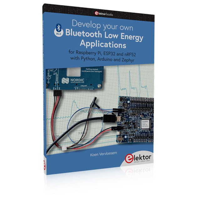
Elektor Publishing Develop your own Bluetooth Low Energy Applications
For Raspberry Pi, ESP32 and nRF52 with Python, Arduino and Zephyr Bluetooth Low Energy (BLE) radio chips are ubiquitous from Raspberry Pi to light bulbs. BLE is an elaborate technology with a comprehensive specification, but the basics are quite accessible. A progressive and systematic approach will lead you far in mastering this wireless communication technique, which is essential for working in low power scenarios. In this book, you’ll learn how to: Discover BLE devices in the neighborhood by listening to their advertisements. Create your own BLE devices advertising data. Connect to BLE devices such as heart rate monitors and proximity reporters. Create secure connections to BLE devices with encryption and authentication. Understand BLE service and profile specifications and implement them. Reverse engineer a BLE device with a proprietary implementation and control it with your own software. Make your BLE devices use as little power as possible. This book shows you the ropes of BLE programming with Python and the Bleak library on a Raspberry Pi or PC, with C++ and NimBLE-Arduino on Espressif’s ESP32 development boards, and with C on one of the development boards supported by the Zephyr real-time operating system, such as Nordic Semiconductor's nRF52 boards. Starting with a very little amount of theory, you’ll develop code right from the beginning. After you’ve completed this book, you’ll know enough to create your own BLE applications.
€ 39,95
Members: € 35,96
-
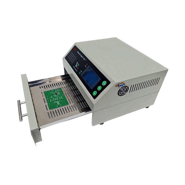
puhui Upgraded T-962 v2.0 Reflow Soldering Oven (Elektor Version)
This upgraded version 2.0 (available exclusively from Elektor) contains the following improvements: Enhanced protective earthing (PE) for furnace chassis Extra thermal insulation layer around furnace to reduce odors Connection to a computer, allowing curve editing on a PC Features such as constant temperature control and timing functions The infrared IC heater T-962 v2.0 is a microprocessor-controlled reflow oven that you can use for effectively soldering various SMD and BGA components. The whole soldering process can be completed automatically and it is very easy to use. This machine uses a powerful infrared emission and circulation of the hot air flow, so the temperature is being kept very accurate and evenly distributed. A windowed drawer is designed to hold the work-piece, and allows safe soldering techniques and the manipulation of SMDBGA and other small electronic parts mounted on a PCB assembly. The T-962 v2.0 may be used to automatically rework solder to correct bad solder joints, remove/replace bad components and complete small engineering models or prototypes. Features Large infrared soldering area Effective soldering area: 180 x 235 mm; this increases the usage range of this machine drastically and makes it an economical investment. Choice of different soldering cycles Parameters of eight soldering cycles are pre defined and the entire soldering process can completed automatically from Preheat, Soak and Reflow through to cool down. Special heat up and temperature equalization with all designs Uses up to 800 Watts of energy efficient Infrared heating and air circulation to re-flow solder. Ergonomic design, practical and easily operated Good build quality but at the same time light weight and a small footprint allows the T-962 v2.0 to be easily bench positioned transported or stored. Large number of available functions The T-962 v2.0 can solder most small parts of PCB boards, for example CHIP, SOP, PLCC, QFP, BGA etc. It is the ideal rework solution from single runs to on-demand small batch production. Specifications Soldering area (max) 180 x 235 mm (7.1 x 9.3") Power (max) 800 W Temperature range 0-280°C (32-536°F) Heating method Infrared Processing time 1~8 minutes Power supply 220 V AC/50 Hz Display LCD with Backlight Control mode 8 intelligent temperature curves Dimensions 310 x 290 x 170 mm (12.2 x 11.4 x 6.7") Weight 6.2 kg Included 1x T-962 v2.0 Reflow Soldering Oven (Elektor Version) 2x Fuses 1x Power cord (EU)
€ 349,00€ 299,00Best Price
-
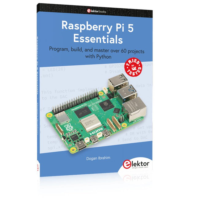
Elektor Publishing Raspberry Pi 5 Essentials
Program, build, and master over 60 projects with Python The Raspberry Pi 5 is the latest single-board computer from the Raspberry Pi Foundation. It can be used in many applications, such as in audio and video media centers, as a desktop computer, in industrial controllers, robotics, and in many domestic and commercial applications. In addition to the well-established features found in other Raspberry Pi computers, the Raspberry Pi 5 offers Wi-Fi and Bluetooth (classic and BLE), which makes it a perfect match for IoT as well as in remote and Internet-based control and monitoring applications. It is now possible to develop many real-time projects such as audio digital signal processing, real-time digital filtering, real-time digital control and monitoring, and many other real-time operations using this tiny powerhouse. The book starts with an introduction to the Raspberry Pi 5 computer and covers the important topics of accessing the computer locally and remotely. Use of the console language commands as well as accessing and using the desktop GUI are described with working examples. The remaining parts of the book cover many Raspberry Pi 5-based hardware projects using components and devices such as LEDs and buzzers LCDs Ultrasonic sensors Temperature and atmospheric pressure sensors The Sense HAT Camera modules Example projects are given using Wi-Fi and Bluetooth modules to send and receive data from smartphones and PCs, and sending real-time temperature and atmospheric pressure data to the cloud. All projects given in the book have been fully tested for correct operation. Only basic programming and electronics experience are required to follow the projects. Brief descriptions, block diagrams, detailed circuit diagrams, and full Python program listings are given for all projects described.
€ 39,95
Members: € 35,96
-
Elektor Publishing Mastering FPGA Chip Design
For Speed, Area, Power, and Reliability This book teaches the fundamentals of FPGA operation, covering basic CMOS transistor theory to designing digital FPGA chips using LUTs, flip-flops, and embedded memories. Ideal for electrical engineers aiming to design large digital chips using FPGA technology. Discover: The inner workings of FPGA architecture and functionality. Hardware Description Languages (HDL) like Verilog and VHDL. The EDA tool flow for converting HDL source into a functional FPGA chip design. Insider tips for reliable, low power, and high performance FPGA designs. Example designs include: Computer-to-FPGA UART serial communication. An open-source Sump3 logic analyzer implementation. A fully functional graphics controller. What you need: Digilent BASYS3 or similar FPGA eval board with an AMD/Xilinx FPGA. Vivado EDA tool suite (available for download from AMD website free of charge). Project source files available from author’s GitHub site.
€ 39,95
Members: € 35,96


