
Search results for "the OR elektor OR power OR supply OR collection OR usb OR stick"
-
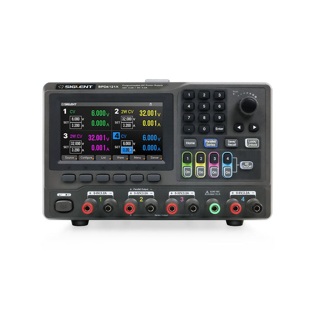
Siglent Siglent SPD4121X 4-ch DC Power Supply (285 W)
The Siglent SPD4121X is a 4-channel DC Linear Programmable Power Supply equipped with a 4.3-inch TFT-LCD display, friendly human-machine interface, and excellent performance indicators. Real-time waveform display provides engineers with an informative user interface. SPD4121X offers a total output power of 285 W with a resolution of 1 mV/1 mA. The maximum voltage and current for each channel are as follows: CH1: 15 V/1.5 A CH2: 12 V/10 A CH3: 12 V/10 A CH4: 15 V/1.5 A Features Rated output power: 285 W Rated voltage: 32 V, 12 V, 30 V Up to four high-precision power supplies with independent controllable outputs, supporting CH2 and CH3 series and parallel connections Clear graphical interface with waveform and timer display modes 5-digit voltage and current display with minimum resolution of 1 mV, 1 mA Fast output response time: <50us The high current channel support remote voltage compensation sense function. The maximum compensation voltage is 0.6 V Overvoltage protection and overcurrent protection or safe and accurate operation Equipped with a 4.3-inch TFT-LCD display (480 x 272 resolution) USB and LAN standard communication USB-GPIB module is optional Excellent channel density with up to 4 channels in a 3U half rack package Internal data storage for setups and parameters Embedded Web Server with instrument communication that doesn’t require software installation Fully SCPI programming command set support as well as a LabView driver for remote control and system automation Specifications SPD4323X SPD4121X SPD4306X Channel Output CH1: Voltage 0 to 6 V Current 0 to 3.2 ACH2: Voltage 0 to 32 V Current 0 to 3.2 ACH3: Voltage 0 to 32 V Current 0 to 3.2 ACH4: Voltage 0 to 6 V Current 0 to 3.2 A CH1: Voltage 0 to 15 V Current 0 to 1.5 ACH2: Voltage 0 to 12 V Current 0 to 10 ACH3: Voltage 0 to 12 V Current 0 to 10 ACH4: Voltage 0 to 15 V Current 0 to 1.5 A CH1: Voltage 0 to 15 V Current 0 to 1.5 ACH2: Voltage 0 to 30 V Current 0 to 6 ACH3: Voltage 0 to 30 V Current 0 to 6 ACH4: Voltage 0 to 15 V Current 0 to 1 A Resolution 1 mV, 1 mA 1 mV, 1 mA 1 mV, 1 mA Setting Accuracy Voltage: ±(0.03% of reading+10) mV, Current: ±(0.3% of reading+10) mA Voltage: ±(0.03% of reading+10) mV, Current: ±(0.3% of reading+10) mA Voltage: ±(0.03% of reading+10) mV, Current: ±(0.3% of reading+10) mA Readback Accuracy Voltage: ±(0.03% of reading+10) mV, Current: ±(0.3% of reading+10) mA Voltage: ±(0.03% of reading+10) mV, Current: ±(0.3% of reading+10) mA Voltage: ±(0.03% of reading+10) mV, Current: ±(0.3% of reading+10) mA Display 4.3" TFT-LCD 5-digit voltage and current display 4.3" TFT-LCD 5-digit voltage and current display 4.3" TFT-LCD 5-digit voltage and current display Output power 240 W 285 W 400 W Included 1x Siglent SPD4121X Power Supply 1x Power cord (EU) 1x Output test cord (3 A) 1x USB cable 1x Quick start guide Downloads Datasheet Manual Quick start
€ 871,20
-

FNIRSI 65 W USB-C PD GaN Power Supply
With this 65 W USB-C PD power supply (with GaN technology) you can start using the FNIRSI HS-01 soldering iron straight away. Of course, you can also use this charger to fast charge your tablets and smartphones via USB-C and USB-A. Included 65 W USB-C PD GaN Power Supply (EU)
€ 25,00
-
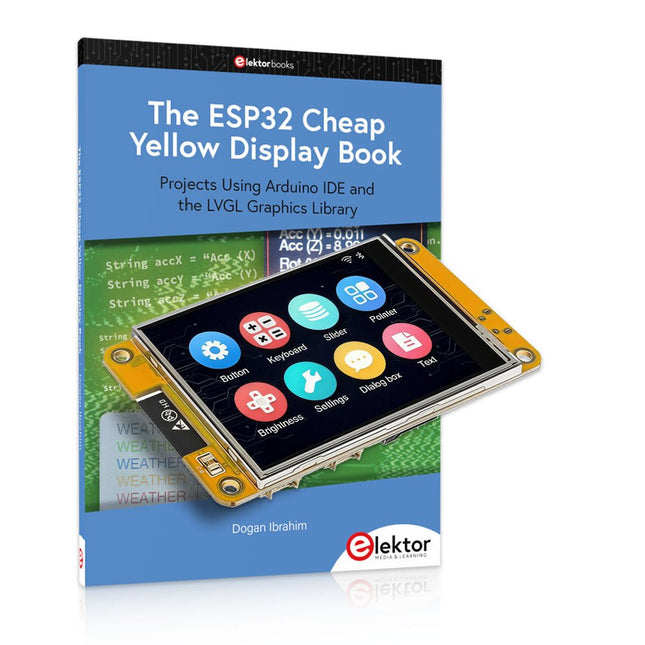
Elektor Bundles The ESP32 Cheap Yellow Display Bundle
Over 40 Fully Tested ESP32 Projects Using Arduino IDE and the LVGL Graphics Library This bundle includes the ESP32 Cheap Yellow Display (CYD) – a compact development board combining a standard ESP32 microcontroller with a 320x240 pixel TFT color display. The board also features multiple connectors for GPIO, serial communication (TX/RX), power, and ground. The built-in display is a major advantage, allowing users to create complex, graphics-based projects without the need for external LCDs or displays. The accompanying book introduces the CYD board's hardware and on-board connectors in detail. It provides a range of beginner to intermediate-level projects developed using the popular Arduino IDE 2.0. Both basic graphics functions and the powerful LVGL graphics library are covered, with practical projects illustrating each approach. All included projects have been fully tested and are ready to use. The book provides block diagrams, circuit schematics, complete code listings, and step-by-step explanations. With the LVGL library, readers can create modern, full-color graphical interfaces using widgets such as buttons, labels, sliders, calendars, keyboards, charts, tables, menus, animations, and more. ESP32 Cheap Yellow Display Board This development board (also known as "Cheap Yellow Display") is powered by the ESP-WROOM-32, a dual-core MCU with integrated Wi-Fi and Bluetooth capabilities. It operates at a main frequency of up to 240 MHz, with 520 KB SRAM, 448 KBROM, and a 4 MB Flash memory. The board features a 2.8-inch display with a resolution of 240x320 and resistive touch. Furthermore, the board includes a backlight control circuit, touch control circuit, speaker drive circuit, photosensitive circuit, and RGB-LED control circuit. It also provides a TF card slot, serial interface, DHT11 temperature and humidity sensor interface, and additional IO ports. The module supports development in Arduino IDE, ESP-IDE, MicroPython, and Mixly. Applications Image transmission for Smart Home device Wireless monitoring Smart agriculture QR wireless recognition Wireless positioning system signal And other IoT applications Specifications Microcontroller ESP-WROOM-32 (Dual-core MCU with integrated Wi-Fi and Bluetooth) Frequency Up to 240 MHz (computing power is up to 600 DMIPS) SRAM 520 KB ROM 448 KB Flash 4 MB Operating voltage 5 V Power consumption approx. 115 mA Display 2.8-inch color TFT screen (240 x 320) Touch Resistive Touch Driver chip ILI9341 Dimensions 50 x 86 mm Weight 50 g Downloads GitHub This bundle contains: The ESP32 Cheap Yellow Display Book (normal price: €35) ESP32 Cheap Yellow Display Board (normal price: €25) 1x ESP32 Dev Board with 2.8" Display and acrylic Shell 1x Touch pen 1x Connector cable 1x USB cable
€ 59,95€ 49,95Best Price
-

Elektor Circuit Special 2025 (DE)
Diese Ausgabe steht allen GOLD- und GREEN-Mitgliedern auf der ElektorMagazine-Website zum Download bereit! Sie sind noch kein Mitglied? Hier klicken! USB-MessadapterStrom und Signalqualität von USB-Anschlüssen testen 4...20 mA Stromausgang für Arduino UnoEine zuverlässige, EMI-unempfindliche Stromschleifenschnittstelle Automatische StaubsaugersteuerungHalten Sie den Arbeitsbereich Ihrer Werkzeuge sauber DDS-Generator mit ATtiny Opamp-Tester V2Neue Platine – nun auch für SMDs geeignet 550-mW-„Lamp“-AudioverstärkerDer warme Klang von Röhren – ganz einfach SicherungswächterSicherung mit Blink-LED überwachen Hochwertiger RIAA-VorverstärkerHolen Sie das Beste aus Ihren Vinyl-Schallplatten heraus! Drahzahlkalibrator für PlattenspielerEin Arduino-basierter Stroboskopgenerator mit 100–120 Hz Infrarot-fernbedienbarer DimmerSteuern Sie Ihre Halogen- oder LED-Stehleuchte mühelos und mit Stil Wie man switch…case mit Strings in C++/Arduino IDE verwendet Magnetfindermit einfachem Hall-Effekt-Sensor Intelligenter Einschaltknopf für Raspberry PiEine Lösung für Raspberry Pi bis zum Modell 4 Essenzielle Maker-TippsProfessionelle Einblicke für den Maker-Alltag Praktische Projekte mit dem 555-TimerGleichstrommotorsteuerung und Reaktionszeitschallungen Einfacher AC-Last-Ein-MonitorEnergie sparen mit einem einfachen Gerät Powerbanks parallel schaltenEine durchgehende Stromversorgung für drei Tage VFO bis 15 MHzMit Raspberry Pi Pico Geigen-Stimmgerät mit ATtiny202 Elektor Classics: Video-Eingangsverstärker für S/W-Fernseher Kapazitätsmesser20 pF bis 600 nF Quasi-analoges Uhrwerk MkIIZwei LED-Ringe für Stunden und Minuten Sie können alles tun, was Sie wollen(mit dem Arduino-Ökosystem an Ihrer Seite) Neon-Würfel mit Glimmlampen Elektor Classics: Video-Verstärker Inspirierende Hardware-Designs für Ihre ESPs Elektor Classics: RTTY-Abgleichanzeige RGB-LEDs mit integrierter SteuerschaltungLicht mit Präzision: ICLEDs setzen Maßstäbe Experiment: Auf dem Weg zu einem Mixed-Signal-Theremin?Moderne Time-of-Flight-Sensoren im Zusammenspiel mit dem zeitlosen XR2206-Analoggenerator ESP32-Audio-Transceiver-Board (Teil 1)SD-Karten-WAV-Player-Demo Infografiken: Schaltungen & Schaltungsdesign 2025 Kleiner Audio-MixerEinfaches und vielseitiges skalierbares Design Intelligenter Treppenlicht-TimerEffiziente Lichtsteuerung zur Reduzierung des Energieverbrauchs Machen Sie Ihre Rollläden smartVelux-Hardware steuern mit ESP32 und MQTT Solid-State-FußwärmerEnergieeffizienter Komfort Ist der M5Stamp Fly Quadcopter der nächste Tello? Erhöhung der WLAN-Reichweite des ESP32-C3 SuperMiniEine einfache und wirkungsvolle Antennenmodifikation ZD-8968 Heißluft-LötstationEin preisgünstiges Arbeitstier oder nur heiße Luft? Parksensor-TesterDefekte beim PDC-System am Auto finden
€ 15,90
-
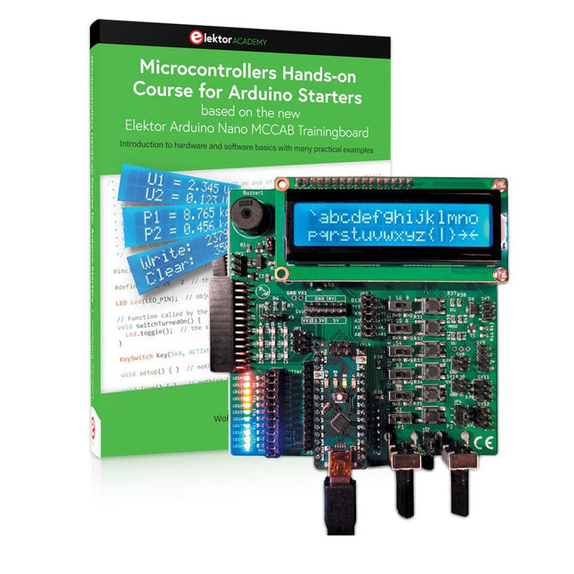
Elektor Bundles Microcontrollers Hands-on Course for Arduino Starters (Bundle)
Realize your own projects with the Elektor Arduino Nano MCCAB Training Board The microcontroller is probably the most fascinating subfield of electronics. Due to the multitude of functions, it combines on its chip, it is a universal multi-tool for developers to realize their projects. Practically every device of daily use today is controlled by a microcontroller. However, for an electronic layman, realizing his own ideas with a microcontroller has so far remained a pipe dream due to its complexity. The Arduino concept has largely simplified the use of microcontrollers, so that now even laymen can realize their own electronics ideas with a microcontroller. Book & Hardware in the Bundle: 'Learning by Doing' This book, which is included in the bundle, shows how you can realize your own projects with a microcontroller even without much experience in electronics and programming languages. It is a microcontrollers hands-on course for starters, because after an overview of the internals of the microcontroller and an introduction to the programming language C, the focus of the course is on the practical exercises. The reader acquires the necessary knowledge by 'learning by doing': in the extensive practical section with 12 projects and 46 exercises, what is learned in the front part of the book is underpinned with many examples. The exercises are structured in such a way that the user is given a task to solve using the knowledge built up in the theoretical part of the book. Each exercise is followed by a sample solution that is explained and commented on in detail, which helps the user to solve problems and compare it with his own solution. Arduino IDE The Arduino IDE is a software development environment that can be downloaded for free to your own PC and that contains the entire software package needed for your own microcontroller projects. You write your programs ('apps') with the IDE’s editor in the C programming language. You translate them into the bits and bytes that the microcontroller understands using the Arduino IDE's built-in compiler, and then load them into the microcontroller's memory on the Elektor Arduino MCCAB Nano Training Board via a USB cable. Query or control external sensors, motors or assemblies In addition to an Arduino Nano microcontroller module, the Elektor Arduino Nano MCCAB Training Board contains all the components required for the exercises, such as light-emitting diodes, switches, pushbuttons, acoustic signal transmitters, etc. External sensors, motors or assemblies can also be queried or controlled with this microcontroller training system. Specifications (Arduino Nano MCCAB Training Board) Power Supply Via the USB connection of the connected PC or an external power supply unit (not included) Operating Voltage +5 Vcc Input Voltage All inputs 0 V to +5 V VX1 and VX2 +8 V to +12 V (only when using an external power supply) Hardware periphery LCD 2x16 characters Potentiometer P1 & P2 JP3: selection of operating voltage of P1 & P2 Distributor SV4: Distributor for the operating voltagesSV5, SV6: Distributor for the inputs/outputs of the microcontroller Switches and buttons RESET button on the Arduino Nano module 6x pushbutton switches K1 ... K6 6x slide switches S1 ... S6 JP2: Connection of the switches with the inputs of the microcontroller Buzzer Piezo buzzer Buzzer1 with jumper on JP6 Indicator lights 11 x LED: Status indicator for the inputs/outputs LED L on the Arduino Nano module, connected to GPIO D13 JP6: Connection of LEDs LD10 ... LD20 with GPIOs D2 ... D12 Serial interfacesSPI & I²C JP4: Selection of the signal at pin X of the SPI connector SV12 SV9 to SV12: SPI interface (3.3 V/5 V) or I²C interface Switching output for external devices SV1, SV7: Switching output (maximum +24 V/160 mA, externally supplied) SV2: 2x13 pins for connection of external modules 3x3 LED matrix(9 red LEDs) SV3: Columns of the 3x3 LED matrix (outputs D6 ... D8) JP1: Connection of the rows with the GPIOs D3 ... D5 Software Library MCCABLib Control of hardware components (switches, buttons, LEDs, 3x3 LED matrix, buzzer) on the MCCAB Training Board Operating Temperature Up to +40 °C Dimensions 100 x 100 x 20 mm Specifications (Arduino Nano) Microcontroller ATmega328P Architecture AVR Operating Voltage 5 V Flash Memory 32 KB, of which 2 KB used by bootloader SRAM 2 KB Clock Speed 16 MHz Analog IN Pins 8 EEPROM 1 KB DC Current per I/O Pins 40 mA on one I/O pin, total maximum 200 mA on all pins together Input Voltage 7-12 V Digital I/O Pins 22 (6 of which are PWM) PWM Output 6 Power Consumption 19 mA Dimensions 18 x 45 mm Weight 7 g Included Elektor Arduino Nano MCCAB Training Board Arduino Nano Book: Microcontrollers Hands-on Course for Arduino Starters
€ 139,95€ 119,95Best Price
-

Elektor Bundles Universal Maker Sensor Bundle
Over 180 Projects with Raspberry Pi, Pico W, Arduino, and ESP32 This bundle contains the Universal Maker Sensor Kit, which consists of many sensors, actuators, displays, and motors. It’s perfect for environmental monitoring, smart home projects, robotics, and game controllers. The new Elektor book describes the design of many projects using the kit together with the popular Raspberry Pi, Raspberry Pi Pico W, Arduino Uno, and the ESP32 family of development boards. You can choose any of these development boards for your projects and either use the provided programs as they are, or modify these programs to suit your applications. This bundle contains: Book: Universal Maker Sensor Kit (normal price: €45) Universal Maker Sensor Kit for Raspberry Pi, Pico W, Arduino, ESP32 (normal price: €70) Book: Universal Maker Sensor Kit Learn to use more than 35 Sensors and Actuators with C++, Python, and MicroPython This book contains over 180 projects for all four major development boards (Arduino, Raspberry Pi, Pico W, and ESP32). Depending on the development board, projects are available in the C, Python, or MicroPython programming languages. The project titles, brief descriptions, wiring diagrams, and full program listings together with their detailed descriptions are given in the guide. Universal Maker Sensor Kit (for Raspberry Pi, Pico W, Arduino, ESP32) Discover endless creativity with the Universal Maker Sensor Kit, designed for use with Raspberry Pi, Pico W, Arduino, and ESP32. This versatile kit offers compatibility across popular development platforms, including Arduino Uno R4 Minima/WiFi, Uno R3, Mega 2560, Raspberry Pi 5, 4, 3B+, 3B, Zero, Pico W, and ESP32. Featuring over 35 sensors, actuators, and displays, it's perfect for projects ranging from environmental monitoring and smart home automation to robotics and interactive gaming. Step-by-step tutorials in C/C++, Python, and MicroPython guide beginners and experienced makers alike through 169 exciting projects. Features Wide Compatibility: Fully supports Arduino (Uno R3, Uno R4 Minima/WiFi, Mega 2560), Raspberry Pi (5, 4, 3B+, 3B, Zero, Pico W), and ESP32, enabling extensive flexibility across numerous development platforms. Includes instructions for building 169 projects. Comprehensive Components: Features more than 35 sensors, actuators, and display modules suitable for diverse projects such as environmental monitoring, smart home automation, robotics, and interactive game controllers. Detailed Tutorials: Provides clear, step-by-step tutorials covering Arduino, Raspberry Pi, Pico W, ESP32, and each included component. Tutorials are available in C/C++, Python, and MicroPython, catering effectively to both beginners and experienced makers. Suitable for All Skill Levels: Offers structured projects designed to guide users seamlessly from beginner to advanced proficiency in electronics and programming, enhancing creativity and technical expertise. Kit includes Breadboard Button Module Capacitive Soil Moisture Module Flame Sensor Module Gas/Smoke Sensor Module (MQ2) Gyroscope & Accelerometer Module (MPU6050) Hall Sensor Module Infrared Speed Sensor Module IR Obstacle Avoidance Sensor Module Joystick Module PCF8591 ADC DAC Converter Module Photoresistor Module PIR Motion Module (HC-SR501) Potentiometer Module Pulse Oximeter and Heart Rate Sensor Module (MAX30102) Raindrop Detection Module Real Time Clock Module (DS1302) Rotary Encoder Module Temperature Sensor Module (DS18B20) Temperature and Humidity Sensor Module (DHT11) Temperature, Humidity & Pressure Sensor (BMP280) Time of Flight Micro-LIDAR Distance Sensor (VL53L0X) Touch Sensor Module Ultrasonic Sensor Module (HC-SR04) Vibration Sensor Module (SW-420) Water Level Sensor Module I²C LCD 1602 OLED Display Module (SSD1306) RGB LED Module Traffic Light Module 5 V Relay Module Centrifugal Pump L9110 Motor Driver Module Passive Buzzer Module Servo Motor (SG90) TT Motor ESP8266 Module JDY-31 Bluetooth Module Power Supply Module Documentation Online Tutorial
€ 114,95€ 94,95Best Price
-
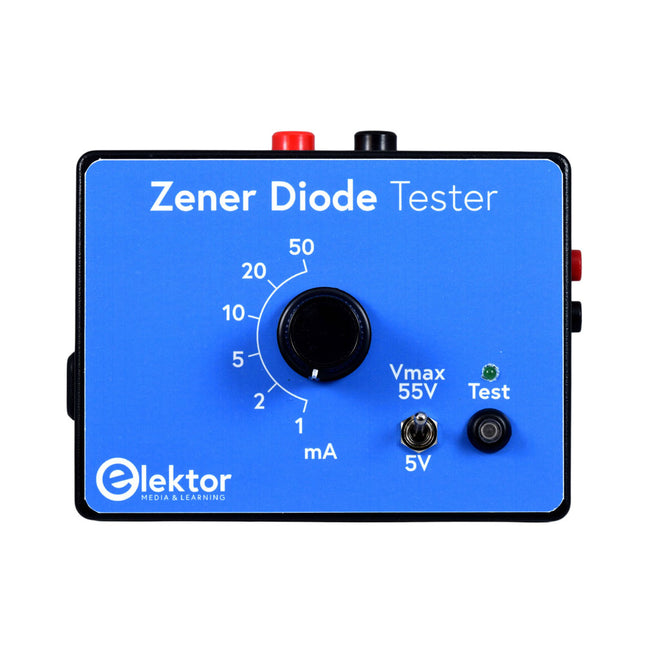
Elektor Zener Diode Tester
The Elektor Zener Diode Tester is essentially a constant-current source that can be switched in steps from 1 to 50 mA. It can be used to test Z-diodes up to a maximum of 54 V. Thanks to a 60-V step-up converter, the device can be powered by the usual 5 to 12 V. The principle of this tester is straightforward. A Z-diode or other DUT (device under test, such as an LED) is biased by an adjustable current source. The voltage across the DUT can be measured with a multimeter. The voltage of most (small) Z-diodes is specified at a current of 5 mA. Depending on the application, the voltage at other currents can also be of interest. That is why six current settings are available: 1, 2, 5, 10, 20, and 50 mA. LEDs are often specified at a current of 20 mA. What can be tested is: Whether a Z-diode is defective (short circuit or high impedance). Whether a Z-diode exhibits the correct Z-voltage. How a Z-voltage changes with different currents. What exact voltage is present at an integrated voltage reference. Whether LEDs in a series chain differ in brightness (hence the 20 mA current). What the current gain is for different base currents in (power) transistors. The kit contains all parts listed in the bill of materials including PCB and enclosure. Specifications Supply voltage 5…12 V/2 A (USB-C) Supply current (Itest = 50 mA) 1.1 A @ 5 V / 412 mA @ 12 V Selectable currents 1, 2, 5, 10, 20, and 50 mA Max. test voltage >54 V @ Itest ≥1 mA Max. output voltage 60 V @ Itest = 0 mA Voltage limit at 5 V 4.5 V @ Itest = 1 mA / 5.18 V @ Itest = 50 mA Enclosure dimensions 110 x 82 x 44 mm PCB size 105.4 x 67.3 mm Connections 4 mm banana sockets for multimeter 2 mm banana sockets for test clips USB-C socket for power supply Included Resistors R1 = 3.3 kΩ, 600 mW, 1% R2 = 0.15 Ω, 1 W, 5%, LS 12.7 mm, ø 3.5 mm R3, R8 = 180 Ω, 600 mW, 1% R4, R6, R16 = 1 kΩ, 600 mW, 1% R5, R19 = 47 kΩ, 600 mW, 1% R7 = 3.9 kΩ, 1 W, 5%, LS 12.7 mm, ø 3.5 mm R9, R10, R12 = 10 kΩ, 600 mW, 1% R11, R13 = 100 Ω, 600 mW 1% R14 = 249 Ω, 600 mW, 1% R15 = 499 Ω, 600 mW, 1% R17 = 2.49 kΩ, 250 mW, 1% R18 = 4.99 kΩ, 250 mW, 1% Capacitors C1 = 470 uF / 35 V, 20%, Ir = 1.86 A, ø 12.5 mm, LS 5 mm, ESR = 0.038 Ω (Panasonic EEUTP1V471) C2 = 1 uF / 100 V, 10%, X7R, LS 5 mm C3 = 2.2 nF / 50 V, 10%, X7R, LS 5 mm C4, C7 = 100 nF / 100 V, 10%, X7R, LS 5 mm C5 = 100 uF / 100 V, 20%, ø 14 mm max., LS 5 mm C6 = 1 nF / 100 V, 10%, X7R, LS 5 mm Inductor L1 = 100 uH, Irms = 2.4 A, Isat = 3.5 A, 0.09 Ω, radial, pitch 2.5/5/10 mm, ø 14 mm max. (Kemet SBC8-101-242) Semiconductors D1 = MUR120G, DO-41 D2, D4 = STPS3150RL, DO-201AD D3 = Z-diode, 18 V, 1.3 W (BZX85C18) D5 = Z-diode, 5.1 V, 0.5 W (1N5231B) LED1 = LED in pushbutton S1 LED2 = LED, green, 3 mm IC1 = MC34063, DIP-8 IC2 = LM4040BIZ-5.0/NOPB, TO-92 (TO-226AA-3) IC3 = TL051CP, DIP-8 T1 = BC327.25, TO-92 T2 = STP40NF10L, TO-220 T3 = IRF9510PBF, TO-220 T4 = 2N7000, TO-92 Others K1, K2, S1, S3 = 2-way screw terminal block, LS 3.5 mm, max. 1.5 mm² connected to K1 = USB-C socket, 30 V/3 A, chassis mounted, wired, 9 x 16 mm connected to K2 = Banana Connector, 2 mm, Socket, 60 VDC, Panel Mount, red (Multicomp 24.102.1) connected to K2 = Banana Connector, 2 mm, Socket, 60 VDC, Panel Mount, black (Multicomp 24.102.2) Test clip, red, 30 VAC/60 VDC (Hirschmann 931467101) Test clip, black, 30 VAC/60 VDC (Hirschmann 931467100) S1 = Pushbutton, panel mount, SPST-NO, 30 DC/100 mA, with red LED S2 = Rotary Switch, 6 position, 2 pole, 30°, 250 V/150 mA S3 = Toggle switch, panel mount, SPDT, solder lugs, 28 VDC T2, T3 = Heat sink, 15°C/W, FK 214 SA-CB Enclosure Hammond 1591XXSSBK, ABS, 110 x 82 x 44 mm Knob for S2, round shaft 6 mm, ø 21 mm, with indicator line (Multicomp CP-LB21-6-6D) 4 x Self-tapping screw #4-1/4", carbon steel, pan head Banana plug, red, 2 mm, 60 VDC (Multicomp 25.205.1) Banana plug, black, 2 mm, 60 VDC (Multicomp 25.205.2) Banana socket, black 4 mm, panel mount Banana socket, red 4 mm, panel mount for LED1, LED2 = Pin header, 1 x 2, vertical, pitch 2.54 mm for LED1, LED2 = Pin socket, 1 x 2, vertical, pitch 2.54 mm for T2, T3 = M3 screw, 10 mm, steel, pan head 2 x M3 washer, plain, steel 4 x M3 nut for IC1, IC3 = DIP-8 socket Wire, black, 0.25 mm² (24 AWG), stranded 14 x 0.15 mm, 1 m Wire, red, 0.25 mm² (24 AWG), stranded 14 x 0.15 mm, 1 m PCB 250772-1 v1.1 Links Article Elektor Labs
€ 99,95€ 79,95Best Price
-

Elektor Labs Elektor 'Wordy' LED Christmas Tree
Multilingual DIY Kit (incl. 27 RGB LEDs + Raspberry Pi Pico) Bring some engineering magic to your festive season with the Wordy LED Christmas Tree, a unique DIY electronics kit designed by Elektor. This beautifully engineered 3D Christmas tree combines eleven PCBs, a Raspberry Pi Pico, and 27 addressable RGB LEDs to illuminate Christmas greetings in seven languages: Danish, Dutch, English, French, German, Italian, and Spanish. Unlike ordinary LED trees, each word inside the tree has its own light chamber, creating a refined, softly glowing display without sound or flicker. The LEDs are fully WS2812-compatible and driven via the popular Adafruit NeoPixel library, making custom animations and color effects easy to create. Perfect for makers, tinkerers, and festive electronics fans, this kit offers both an enjoyable build and a striking, conversation-worthy decoration. The Wordy Christmas Tree is your perfect holiday maker project! Features Multilingual greetings (7 languages) milled into the front panel 3D construction from 11 interlocking PCBs Powered by Raspberry Pi Pico 27 individually addressable RGB LEDs (pre-mounted) Smooth fade-in and fade-out animations Fully programmable using the Arduino IDE A 5-V power supply (with micro-USB connector) capable of ≥1 A is recommended for maximum brightness (not included) Dimensions (H x W x D): 130 x 115 x 75 mm Included All required PCBs with LEDs and other SMD parts mounted Raspberry Pi Pico (to be soldered & programmed by the user) 3-way pin header (to be soldered by the user) 3-way pin socket (to be soldered by the user) 4x Self-adhesive dome bumpers Project Page Elektor Labs
€ 59,95€ 49,95Best Price
-
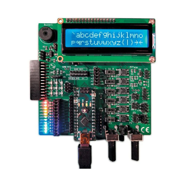
Elektor Labs Elektor Arduino Nano MCCAB Training Board
The Elektor Arduino Nano MCCAB Training Board contains all the components (incl. Arduino Nano) required for the exercises in the "Microcontrollers Hands-on Course for Arduino Starters", such as light-emitting diodes, switches, pushbuttons, acoustic signal transmitters, etc. External sensors, motors or assemblies can also be queried or controlled with this microcontroller training system. Specifications (Arduino Nano MCCAB Training Board) Power Supply Via the USB connection of the connected PC or an external power supply unit (not included) Operating Voltage +5 Vcc Input Voltage All inputs 0 V to +5 V VX1 and VX2 +8 V to +12 V (only when using an external power supply) Hardware periphery LCD 2x16 characters Potentiometer P1 & P2 JP3: selection of operating voltage of P1 & P2 Distributor SV4: Distributor for the operating voltagesSV5, SV6: Distributor for the inputs/outputs of the microcontroller Switches and buttons RESET button on the Arduino Nano module 6x pushbutton switches K1 ... K6 6x slide switches S1 ... S6 JP2: Connection of the switches with the inputs of the microcontroller Buzzer Piezo buzzer Buzzer1 with jumper on JP6 Indicator lights 11 x LED: Status indicator for the inputs/outputs LED L on the Arduino Nano module, connected to GPIO D13 JP6: Connection of LEDs LD10 ... LD20 with GPIOs D2 ... D12 Serial interfacesSPI & I²C JP4: Selection of the signal at pin X of the SPI connector SV12 SV9 to SV12: SPI interface (3.3 V/5 V) or I²C interface Switching output for external devices SV1, SV7: Switching output (maximum +24 V/160 mA, externally supplied) SV2: 2x13 pins for connection of external modules 3x3 LED matrix(9 red LEDs) SV3: Columns of the 3x3 LED matrix (outputs D6 ... D8) JP1: Connection of the rows with the GPIOs D3 ... D5 Software Library MCCABLib Control of hardware components (switches, buttons, LEDs, 3x3 LED matrix, buzzer) on the MCCAB Training Board Operating Temperature Up to +40 °C Dimensions 100 x 100 x 20 mm Specifications (Arduino Nano) Microcontroller ATmega328P Architecture AVR Operating Voltage 5 V Flash Memory 32 KB, of which 2 KB used by bootloader SRAM 2 KB Clock Speed 16 MHz Analog IN Pins 8 EEPROM 1 KB DC Current per I/O Pins 40 mA on one I/O pin, total maximum 200 mA on all pins together Input Voltage 7-12 V Digital I/O Pins 22 (6 of which are PWM) PWM Output 6 Power Consumption 19 mA Dimensions 18 x 45 mm Weight 7 g Included 1x Elektor Arduino Nano Training Board MCCAB 1x Arduino Nano
€ 79,95€ 69,95Best Price
-
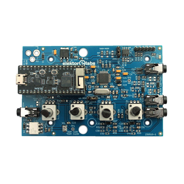
Elektor Labs Elektor Audio DSP FX Processor (New Revision)
The Elektor Audio DSP FX Processor combines an ESP32 microcontroller and an ADAU1701 Audio DSP from Analog Devices. Besides a user-programmable DSP core, the ADAU1701 has high-quality analog-to-digital and digital-to-analog converters built-in and features an I²S port. This makes it suitable as a high-quality audio interface for the ESP32. Programs for the ESP32 can be created with Arduino, Platform IO, CMake or by using the Espressif IDF in another way. Programs for the ADAU7101 audio DSPs are created with the free visual programming tool SigmaStudio by dragging and dropping pre-defined algorithm blocks on a canvas. Applications Bluetooth/Wi-Fi audio sink (e.g. loudspeaker) & source Guitar effect pedal (stomp box) Music synthesizer Sound/function generator Programmable cross-over filter for loudspeakers Advanced audio effects processor (reverb, chorus, pitch shifting, etc.) Internet-connected audio device DSP experimentation platform Wireless MIDI MIDI to CV converter and many more... Specifications ADAU1701 28-/56-bit, 50-MIPS digital audio processor supporting sampling rates of up to 192 kHz ESP32 32-bit dual-core microcontroller with Wi-Fi 802.11b/g/n and Bluetooth 4.2 BR/EDR and BLE 2x 24-bit audio inputs (2 V RMS, 20 kΩ) 4x 24-bit audio outputs (0.9 V RMS, 600 Ω) 4x Control potentiometer MIDI in- and output I²C expansion port Multi-mode operation Power supply: 5 V DC USB or 7.5-12 V DC (barrel jack, center pin is GND) Current consumption (average): 200 mA Included 1x ESP32 Audio DSP FX Processor board (assembled) 1x ESP32-PICO-KIT 2x Jumpers 2x 18-pin headers (female) 4x 10 KB potentiometers Downloads Documentation GitHub
€ 99,95€ 84,95Best Price
-
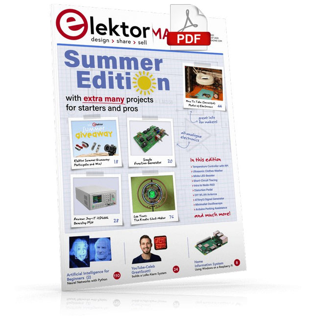
Elektor Digital Elektor July/August 2020 (PDF) EN
Home Information SystemUsing Windows on a Raspberry Pi Starting with Node-REDAn open-source visual block-based programming tool Elektor Summer GiveAway Simple Function Generator: With Reverse-Order Signal Creation GreatScott! Builds a LoRa Alarm System Review: Joy-iT RD6006 Benchtop Power Supply Kit Review: The GreatFET One Interface Board Small Circuits Revival – XXLEscaped from the Suggestions Box Poorest Man's External 2.4 GHz Wi-Fi Antenna Simple On-Off Temperature Controller with Raspberry Pi HAT How to Take (Successful) Photos of ElectronicsShowing your projects in their best light Review: The I2CDriver Tool Review: JOY-iT Joy-View Portable Touchscreen LED Booster for MicrocontrollersWith just one component Experimental Ultrasonic Clothes Washer Review: The Joy-iT JDS2915 Signal GeneratorA 2-Channel Signal Generator and Frequency Counter Traffic Lights Programmed in PIC Assembly Code E-E-E-ternal Blinker Experimental Hall Sensor Tracing Shorts with the Milli-Ohm or ESR Meter Review: Elektor SDR Hands-on Kit Elektor Labs Pipeline Elektor KickstarterWell, you get the idea. Do You Really Need All That Stuff???This is where I spend many hours working on electronics projects Homelab Tours: The Kinetic Clock MakerStargate jigsawed! Hello, World! We’re Elektor, and We’re Social M4 + 2x A7 + GPU: An Unbalanced Dream TeamLatest STM32MP1-SoCs can tackle demanding applications Test Rig for 16F18877 & Similar Big PICs Inter-Microcontroller Traffic with the SPI Bus and ATmega328p Six Shades of LF/AF OSC (and the Miller’s Tale) BBC micro:bit Absolute Minimalist Oscilloscope with LED Display ‘Knight Rider’ LED Chaser with the ESP32 LW/MW AM Signal Generator with ATtiny13 Absolute Minimalist Dip Meter Photovoltaic Regulator UpdateNew function for measuring battery temperature Wireless SignallingTransmitting switching signals over LPR Ultrasonic Reverse Parking Aid with Arduino Uno Distortion Pedal with Op Amp and Space Charge Tubes Electronics Workspace Essentials Hexadoku Artificial Intelligence for Beginners (2)Neural networks with Linux and Python
€ 7,50
-

Elektor 01-02/2026 (DE)
Diese Ausgabe steht allen GOLD- und GREEN-Mitgliedern auf der ElektorMagazine-Website zum Download bereit! Sie sind noch kein Mitglied? Hier klicken! Rauscharmes Labor-Netzteil (Teil 1)Eine stille Quelle für empfindliche Schaltungen STM32 Edge AI Contest 2025: Die Gewinner Batterien 2025Technik und Unterschiede bei Lithium-Batterien Einstellbare elektronische LastGleichstromlast statisch und dynamisch Abwärtswandler von 48 V auf 5 VGeschichte einer Schaltungsentwicklung Autonomer Sensorknoten v2.0Teil 2: Hardware-Validierung und Leistungsoptimierungen VaristorenBemerkenswerte Bauteile – die Serie Grafische NetzfrequenzlupeDie Netzqualität überwachen Aller Anfang ...... führt zu einem Ende Multilayer Power Suppression BeadsBreitbandige Entstörung bei hoher Spitzenstrombelastbarkeit Elektor Live! Expert Day 2025 Energy Harvesting zur Beschleunigung von IoT- und IIoT-AnwendungenSo entkoppelt Energy Harvesting das IoT vom Stromnetz Fnirsi DPS-150Kompakte und tragbare Stromversorgung und Wandler Einstellbare USB-C-StromquelleMachen Sie aus Ihrem USB-C-Ladegerät ein einstellbares Netzteil Einfacher Lade- und KapazitätstesterMit zwei günstigen „Off-the-Shelf“-Modulen Sprechender FarbdetektorMit MP3-Player-Modul und KI-generierter Stimme PbMonitor v2.0Einführung in das aktualisierte Batterie-Überwachungssystem Ein Lüfter für die Mini-Reflow-PlatteNichts ist so gut, dass man es nicht verbessern könnte Aus dem Leben gegriffenDie Flut der Versuchungen Projekt 2.0Korrekturen, Updates und Leserbriefe 2026: Eine KI-OdysseeWenn Modelle die Hardware bestimmen Präzisions-Picoamperemeter (Teil 2)Zusammenbau, Kalibrierung und Test Stromversorgung ohne Kabelmit Induktionstechnik KI-gestütztes autonomes FahrenDie RDW Self Driving Challenge 2024 Soundkarte als SignalgeneratorPC als DCF77-Testsender
€ 15,90


