Pfiffige Projekte zum Messen, Steuern und Regeln
Der Raspberry Pi dominiert seit vielen Jahren die Maker-Szene. Frei verfügbare I/O-Pins machten ihn zu einem der beliebtesten Prozessorboards aller Zeiten. Allerdings verfügt der klassische Raspberry Pi über keinerlei Analogeingänge. Eine direkte Messung analoger Werte ist damit nicht möglich. So können weder Photodioden noch NTCs oder Hallsensoren etc. unmittelbar ausgelesen werden. Zudem sind die Pins direkt, d. h. ohne Treiber oder Schutzschaltung, mit den freiliegenden Kontakten verbunden. Dadurch kann der zentrale Controller und damit der gesamte Raspberry Pi schnell zerstört werden.
Mit dem Pico können diese Probleme elegant gelöst werden. Er kann als sogenanntes „Frontend“ problemlos vielfältige Messaufgaben übernehmen. Zudem ist der Pico deutlich preisgünstiger als ein klassischer Raspberry Pi 4. Falls eine Fehlbeschaltung zur Zerstörung des Pico führt, ist dies vor allem für nicht-professionelle Anwender relativ leicht zu verkraften. Der klassische Raspberry Pi und der Pico werden so zum idealen Duo.
Das Buch führt entsprechend in das weite und hochaktuelle Gebiet der modernen Controllertechnik anhand der beiden Boards „Raspberry Pi 4“ und „Raspberry Pi Pico“ ein. Neben einer tiefergehenden Einführung in die Arbeits- und Funktionsweise der Controllerboards selbst wird insbesondere auch auf die Messwerterfassung und -verarbeitung mit digitalen Prozessoren eingegangen. Insbesondere die Kombination beider Systeme bietet vielfältige und hochinteressante Möglichkeiten.
Praktische Projekte aus dem Inhalt:
USB-Verbindung zwischen Raspberry Pi 4 und Pico
I²C-Kommunikation und Pico als I²C-Device
Voltmeter und Computerthermometer
Pico W als Web-Server und WLAN-Scanner
Frequenzmesser und -generatoren
OLED-Displays an Pico und Raspberry Pi 4
Energiesparmonitor
Welche Astronauten sind im Orbit?
Mini-Monitor für den aktuellen Bitcoin-Kurs
Build Your Own Vintage Radio Broadcaster
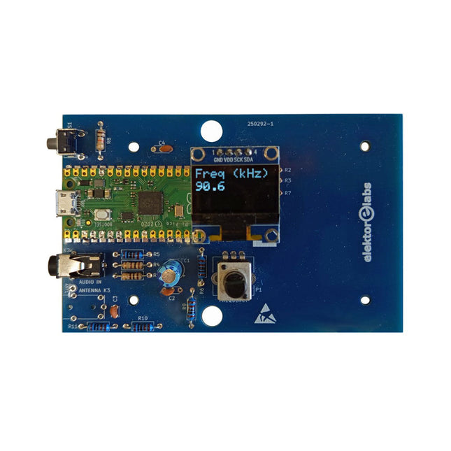
The Elektor AM Transmitter Kit allows streaming audio to vintage AM radio receivers. Based on a Raspberry Pi Pico microcontroller module, the AM Transmitter can transmit on 32 frequencies in the AM band, from 500 kHz up to 1.6 MHz in 32 steps of approx. 35 kHz.
The frequency is selected with a potentiometer and shown on a 0.96" OLED display. A pushbutton allows toggles the transmitting mode between On and Off. The range of the transmitter depends on the antenna. The onboard antenna provides a range of a few centimeters, requiring the AM Transmitter to be placed close to or inside the radio. An external loop antenna (not included) can be connected to increase the range.
The Elektor AM Transmitter Kit comes as a kit of parts that you must solder to the board yourself.
Features
The board is compatible with a Hammond 1593N enclosure (not included).A 5 VDC power supply with micro-USB connector (e.g., an old phone charger) is needed to power the kit (not included). Current consumption is 100 mA.
The Arduino software (requiring Earle Philhower’s RP2040 Boards Package) for the Elektor AM Transmitter Kit plus more information is available at the Elektor Labs page of this project.
Component List
Resistors
R1, R4 = 100 Ω
R2, R3, R8 = 10 kΩ
R5, R6, R9, R10, R11 = 1 kΩ
R7 = optional (not included)
P1 = potentiometer 100 kΩ, linear
Capacitors
C1 = 22 µF 16V
C2, C4 = 10 nF
C3 = 150 pF
Miscellaneous
K1 = 4×1 pin socket
K2, K3 = 3.5 mm socket
Raspberry Pi Pico
pushbutton, angle mount
0.96" monochrome I²C OLED display
PCB 150292-1
Projects with Arduino Uno & Raspberry Pi with Examples for the MCP2515 CAN Bus Interface Module
This book details the use of the Arduino Uno and the Raspberry Pi 4 in practical CAN bus based projects. Using either the Arduino Uno or the Raspberry Pi with off-the-shelf CAN bus interface modules considerably ease developing, debugging, and testing CAN bus based projects.
This book is written for students, practicing engineers, enthusiasts, and for everyone else wanting to learn more about the CAN bus and its applications. The book assumes that the reader has some knowledge of basic electronics. Knowledge of the C and Python programming languages and programming the Arduino Uno using its IDE and Raspberry Pi will be useful, especially if the reader intends to develop microcontroller-based projects using the CAN bus.
The book should be a useful source of reference material for anyone interested in finding answers to questions such as:
What bus systems are available for the automotive industry?
What are the principles of the CAN bus?
How can I create a physical CAN bus?
What types of frames (or data packets) are available in a CAN bus system?
How can errors be detected in a CAN bus system and how dependable is a CAN bus system?
What types of CAN bus controllers exist?
How do I use the MCP2515 CAN bus controller?
How do I create 2-node Arduino Uno-based CAN bus projects?
How do I create 3-node Arduino Uno-based CAN bus projects?
How do I set the acceptance masks and acceptance filters?
How do I analyze data on the CAN bus?
How do I create 2-node Raspberry Pi-based CAN bus projects?
How do I create 3-node Raspberry Pi-based CAN bus projects?
Zeitsteuerung, Scheduler, PIO und Zustandsmaschinen
Multitasking ist der Schlüssel zu leistungsfähigen Embedded-Systemen, und zugleich eine der größten Herausforderungen in der Mikrocontroller-Programmierung. Dieses Buch zeigt Ihnen Schritt für Schritt, wie Sie von einem einfachen Ein-Task-Programm zu einem strukturierten, reaktionsfähigen und skalierbaren System gelangen. Dabei steht nicht nur das Wie, sondern vor allem das Warum im Mittelpunkt.
Sie lernen:
warum scheinbare Parallelität entsteht
weshalb blockierende Programme instabil werden
wie Aufgaben effizient und kontrolliert parallel ablaufen
Ausgehend vom klassischen Superloop vermittelt das Buch moderne Multitasking-Strategien – von nicht-blockierender Programmierung und Tick-Systemen bis zu Task-Schedulern, Zustandsmaschinen und ereignisgesteuerten Konzepten.
Der Fokus liegt auf der Praxis: Sensoren, Displays, Kommunikation und reale Anwendungen werden Schritt für Schritt integriert und mit verständlich kommentierten Beispielprogrammen erklärt.
Fortgeschrittene Themen umfassen:
Multicore-Programmierung mit dem Raspberry Pi Pico
asynchrones Programmieren mit uasyncio
RTOS-Grundlagen mit FreeRTOS
die Kombination aus Multicore und RTOS
Dabei werden auch die Grenzen dieser Techniken, insbesondere unter MicroPython, klar aufgezeigt.
Das Buch richtet sich an ambitionierte Einsteiger und fortgeschrittene Entwickler, die Embedded-Systeme fundiert verstehen und robuste, wartbare Multitasking-Anwendungen entwickeln möchten.
Raspberry Pi-based Eye Catcher
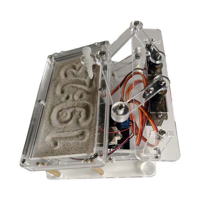
A standard sand clock just shows how time passes. In contrast, this Raspberry Pi Pico-controlled sand clock shows the exact time by “engraving” the four digits for hour and minute into the layer of sand. After an adjustable time the sand is flattened out by two vibration motors and everything begins all over again.
At the heart of the sand clock are two servo motors driving a writing pen through a pantograph mechanism. A third servo motor lifts the pen up and down. The sand container is equipped with two vibration motors to flatten the sand. The electronic part of the sand clock consists of a Raspberry Pi Pico and an RTC/driver board with a real-time clock, plus driver circuits for the servo motors.
A detailed construction manual is available for downloading.
Features
Dimensions: 135 x 110 x 80 mm
Build time: approx. 1.5 to 2 hours
Included
3x Precut acrylic sheets with all mechanical parts
3x Mini servo motors
2x Vibration motors
1x Raspberry Pi Pico
1x RTC/driver board with assembled parts
Nuts, bolts, spacers, and wires for the assembly
Fine-grained white sand
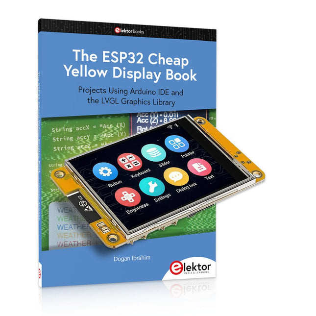
Over 40 Fully Tested ESP32 Projects Using Arduino IDE and the LVGL Graphics Library
This bundle includes the ESP32 Cheap Yellow Display (CYD) – a compact development board combining a standard ESP32 microcontroller with a 320x240 pixel TFT color display. The board also features multiple connectors for GPIO, serial communication (TX/RX), power, and ground. The built-in display is a major advantage, allowing users to create complex, graphics-based projects without the need for external LCDs or displays.
The accompanying book introduces the CYD board's hardware and on-board connectors in detail. It provides a range of beginner to intermediate-level projects developed using the popular Arduino IDE 2.0. Both basic graphics functions and the powerful LVGL graphics library are covered, with practical projects illustrating each approach.
All included projects have been fully tested and are ready to use. The book provides block diagrams, circuit schematics, complete code listings, and step-by-step explanations. With the LVGL library, readers can create modern, full-color graphical interfaces using widgets such as buttons, labels, sliders, calendars, keyboards, charts, tables, menus, animations, and more.
ESP32 Cheap Yellow Display Board
This development board (also known as "Cheap Yellow Display") is powered by the ESP-WROOM-32, a dual-core MCU with integrated Wi-Fi and Bluetooth capabilities. It operates at a main frequency of up to 240 MHz, with 520 KB SRAM, 448 KBROM, and a 4 MB Flash memory. The board features a 2.8-inch display with a resolution of 240x320 and resistive touch.
Furthermore, the board includes a backlight control circuit, touch control circuit, speaker drive circuit, photosensitive circuit, and RGB-LED control circuit. It also provides a TF card slot, serial interface, DHT11 temperature and humidity sensor interface, and additional IO ports.
The module supports development in Arduino IDE, ESP-IDE, MicroPython, and Mixly.
Applications
Image transmission for Smart Home device
Wireless monitoring
Smart agriculture
QR wireless recognition
Wireless positioning system signal
And other IoT applications
Specifications
Microcontroller
ESP-WROOM-32 (Dual-core MCU with integrated Wi-Fi and Bluetooth)
Frequency
Up to 240 MHz (computing power is up to 600 DMIPS)
SRAM
520 KB
ROM
448 KB
Flash
4 MB
Operating voltage
5 V
Power consumption
approx. 115 mA
Display
2.8-inch color TFT screen (240 x 320)
Touch
Resistive Touch
Driver chip
ILI9341
Dimensions
50 x 86 mm
Weight
50 g
Downloads
GitHub
This bundle contains:
The ESP32 Cheap Yellow Display Book (normal price: €35)
ESP32 Cheap Yellow Display Board (normal price: €25)
1x ESP32 Dev Board with 2.8" Display and acrylic Shell
1x Touch pen
1x Connector cable
1x USB cable
Buch: Logic Analyzer im Einsatz
Schritt-für-Schritt-Anleitungen führen Sie in die Analyse moderner Protokolle von I²C, SPI, UART, RS-232, NeoPixel, WS28xx, HD44780 und 1-Wire ein. Anhand von zahlreichen Experimentierschaltungen mit dem Raspberry Pi Pico, Arduino Uno und dem Bus Pirate üben Sie die praxisnahe Anwendung gängiger USB-Logikanalysatoren ein.
Alle in diesem Buch vorgestellten Experimentierschaltungen wurden vollständig getestet und sind funktionsfähig. Die notwendigen Programmlistings sind enthalten, es sind keine besonderen Programmier- oder Elektronikkenntnisse für diese Schaltungen notwendig. Es werden die Programmiersprachen MicroPython und C mit den Entwicklungsumgebungen Thonny und Arduino IDE eingesetzt.
Dieses Buch verwendet mehrere Modelle flexibler und weit verbreiteter USB-Logikanalysatoren und zeigt die Stärken und Schwächen jeder Preisklasse. Sie werden kennenlernen, welche Kriterien für Ihre Arbeit wichtig sind und in der Lage sein, das für Sie passende Gerät zu finden.
Egal ob Arduino, Raspberry Pi oder Raspberry Pi Pico: Die abgebildeten Beispielschaltungen ermöglichen einen schnellen Start in die Protokollanalyse und können auch als Grundlage für eigene weitere Experimente dienen.
Sie werden alle wichtigen Begriffe und Zusammenhänge kennenlernen, eigene Experimente durchführen, selbstständig Protokolle analysieren und nach der Lektüre dieses Buches – im Bereich der digitalen Signale und Protokolle – ein umfassendes Wissen aufgebaut haben.
USB Logic Analyzer (8 Kanäle, 24 MHz)
Dieser USB Logic Analyzer ist ein 8-Kanal-Logikanalysator, bei dem jeder Eingang doppelt für die analoge Datenaufzeichnung dient. Es eignet sich perfekt zum Debuggen und Analysieren von Signalen wie I²C, UART, SPI, CAN und 1-Wire. Dabei wird ein digitaler Eingang, der mit einem zu testenden Gerät (DUT) verbunden ist, mit einer hohen Abtastrate abgetastet. Die Verbindung zum PC erfolgt via USB.
Technische Daten
Kanäle
8 digitale Kanäle
Maximale Abtastrate
24 MHz
Maximale Eingangsspannung
0 V ~ 5 V
Betriebstemperatur
0°C ~ 70°C
Eingangsimpedanz
1 MΩ || 10 pF
Unterstützte Protokolle
I²C, SPI, UART, CAN, 1-Wire etc.
PC-Verbindung
USB
Abmessungen
55 x 28 x 14 mm
Downloads
Software
Dieses Bundle enthält:
Buch: Logic Analyzer im Einsatz (Einzelpreis: 40 €)
USB Logic Analyzer (8 Kanäle, 24 MHz) (Einzelpreis: 20 €)
USB-Kabel
Jumper Wire Ribbon Kabel
The Joy-Pi Advanced is a compact and powerful device that allows you to realize your projects quickly and easily. Whether you already have a lot of experience, or next to none, the Joy-Pi Advanced lets you unleash your creativity. Thanks to its compatibility with a wide range of platforms, including Raspberry Pi, Raspberry Pi Pico, Arduino Nano, BBC micro:bit, and NodeMCU ESP32, you can easily and quickly access your preferred platform.
In addition, the Joy-Pi Advanced features more than 30 stations, lessons, and modules, giving you an unlimited variety of ways to get your projects done. With the self-developed learning center, you can not only improve your skills but also create new projects. The learning center offers a wealth of information and tutorials that will guide you step by step through your projects.
Joy-Pi Advanced is characterized in particular by its intelligent switch units, which allow an extended use of the available pins. A total of three switch units are integrated, each equipped with 12 individual switches that provide precise control of the connected sensors and modules. This system solves the well-known problem of limited pin count that occurs with conventional microcontrollers. The switch units allow you to operate a large number of sensors and modules in parallel by switching them on and off individually. This simulates multiple pin assignment, allowing you to exploit the full power of your projects without compromising functionality.
By combining innovative adapter boards and the micro:bit slot, you can achieve seamless compatibility with a wide range of microcontrollers such as Raspberry Pi Pico, NodeMCU ESP32, micro:mit and Arduino Nano. The specially developed adapter boards are designed to perfectly match the respective microcontroller. By plugging the microcontroller onto the appropriate adapter board and then plugging it into the micro:bit slot, the Joy-Pi Advanced quickly and easily becomes compatible with the different microcontrollers. This allows seamless integration of your preferred platform and the ability to combine the strengths of the different microcontrollers in your projects. This way, you can fully focus on your creative projects without worrying about the compatibility of different microcontrollers. The Joy-Pi Advanced simplifies the development process and gives you the possibility to design your projects flexibly and individually.
Features
Highly integrated development platform & learning center
Fast, easy & wireless combination of various sensors & actuators
Installation option for Raspberry Pi 4
Compatible with various microcontrollers
Self-developed, didactic learning platform for Raspberry Pi & Windows
Specifications
Compatible to
Raspberry Pi 4, Arduino Nano, NodeMCU ESP32, BBC micro:bit, Raspberry Pi Pico
Installed sensors, actuators & components
39
Learning platform
Over 40 entries in the know-ledge database, 10 projects, 10 learning tasks, 14 visions
Displays
7-segment display, 16x2 display, 1.8“ TFT display, 0.96" OLED display, 8x8 RGB matrix
Sensors
DS18B20, shock sensor, hall sensor, barometer, sound sensor, gyroscope, PIR sensor, Light barrier, NTC, Light sensor, 6x touch sensor, color sensor, ultrasonic distance sensor, DHT11 temperature & humidity sensor
Control
Joystick, 5x switches, potentiometer, rotary encoder, 4x4 button matrix, relays, PWM fan
Motors
Servo interface, Stepper motor interface, Vibration motor
Measuring & conversion modules
Analog-Digital Converter, Level converter, voltmeter, Variable voltage supply
Other components
RTC real time clock, buzzer, EEPROM memory, infrared receiver, breadboard, RFID reader
Adapter boards
Adapter for NodeMCU ESP32, Arduino Nano & Raspberry Pi Pico, Board connectors for Raspberry Pi & External Boards
Electronic components
Infrared remote control, RFID chip, RFID card, 6x alligator clips, microSD card reader, servo motor, stepper motor, 32 GB microSD card
Components
40x resistors, 3x green LEDs, 3x yellow LEDs, 3x red LEDs, 1x transistor, 5x buttons, 1x potentiometer, 2x capacitors
Other accessories
Screw assortment, screwdriver, accessory storage bag, power supply & power cable, servo mount
Power supply
Built-in power supply: 36 W, 12 V, 3 A Case connector: Small device plug C8
Voltage outputs
12 V, 5 V, 3.3 V, Variable voltage output (2-11 V)
Data buses & signal outputs
I²C, SPI, Analog to digital converter
Battery (RTC)
CR2032
Dimensions
327 x 200 x 52 mm
Included
Raspberry Pi 4 (8 GB RAM)
Downloads
Joy-Pi website
Datasheet
Manual
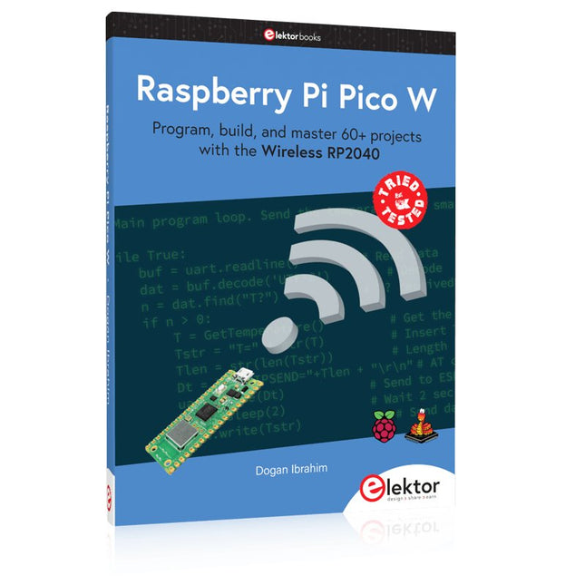
Program, build, and master 60+ projects with the Wireless RP2040
The Raspberry Pi Pico and Pico W are based on the fast, efficient, and low-cost dual-core ARM Cortex M0+ RP2040 microcontroller chip running at up to 133 MHz and sporting 264 KB of SRAM and 2 MB of Flash memory. Besides spacious memory, the Pico and Pico W offer many GPIO pins, and popular peripheral interface modules like ADC, SPI, I²C, UART, PWM, timing modules, a hardware debug interface, and an internal temperature sensor.
The Raspberry Pi Pico W additionally includes an on-board Infineon CYW43439 Bluetooth and Wi-Fi chipset. At the time of writing this book, the Bluetooth firmware was not yet available. Wi-Fi is however fully supported at 2.4 GHz using the 802.11b/g/n protocols.
This book is an introduction to using the Raspberry Pi Pico W in conjunction with the MicroPython programming language. The Thonny development environment (IDE) is used in all of the 60+ working and tested projects covering the following topics:
Installing the MicroPython on Raspberry Pi Pico using a Raspberry Pi or a PC
Timer interrupts and external interrupts
Analogue-to-digital converter (ADC) projects
Using the internal temperature sensor and external sensor chips
Using the internal temperature sensor and external temperature sensor chips
Datalogging projects
PWM, UART, I²C, and SPI projects
Using Bluetooth, WiFi, and apps to communicate with smartphones
Digital-to-analogue converter (DAC) projects
All projects are tried & tested. They can be implemented on both the Raspberry Pi Pico and Raspberry Pi Pico W, although the Wi-Fi-based subjects will run on the Pico W only. Basic programming and electronics experience are required to follow the projects. Brief descriptions, block diagrams, detailed circuit diagrams, and full MicroPython program listings are given for all projects.
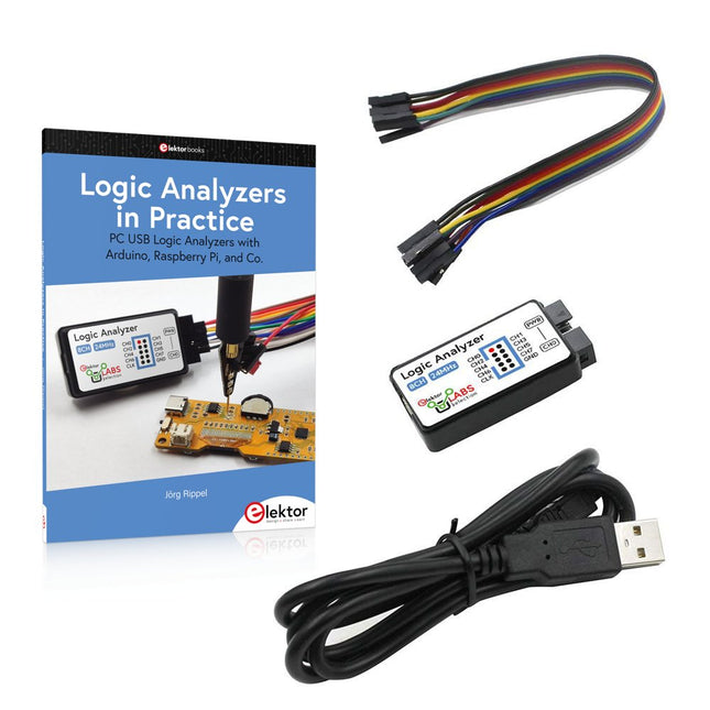
Book: Logic Analyzers in Practice
Step-by-step instructions guide you through the analysis of modern protocols such as I²C, SPI, UART, RS-232, NeoPixel, WS28xx, HD44780 and 1-Wire. With the help of numerous experimental circuits based on the Raspberry Pi Pico, Arduino Uno and the Bus Pirate, you will learn the practical application of popular USB logic analyzers.
All the experimental circuits presented in this book have been fully tested and are fully functional. The necessary program listings are included – no special programming or electronics knowledge is required for these circuits. The programming languages used are MicroPython and C along with the development environments Thonny and Arduino IDE.
This book uses several models of flexible and widely available USB logic analyzers and shows the strengths and weaknesses of each price range.
You will learn about the criteria that matter for your work and be able to find the right device for you.
Whether Arduino, Raspberry Pi or Raspberry Pi Pico, the example circuits shown allow you to get started quickly with protocol analysis and can also serve as a basis for your own experiments.
After reading this book, you will be familiar with all the important terms and contexts, conduct your own experiments, analyze protocols independently, culminating in a comprehensive knowledge set of digital signals and protocols.
USB Logic Analyzer (8-ch, 24 MHz)
This USB Logic Analyzer is an 8-channel logic analyzer with each input dual purposed for analog data recording. It is perfect for debugging and analyzing signals like I²C, UART, SPI, CAN and 1-Wire. It operates by sampling a digital input connected to a device under test (DUT) at a high sample rate. The connection to the PC is via USB.
Specifications
Channels
8 digital channels
Maximum sampling rate
24 MHz
Maximum input voltage
0 V ~ 5 V
Operating temperature
0°C ~ 70°C
Input impedance
1 MΩ || 10 pF
Supported protocols
I²C, SPI, UART, CAN, 1-Wire, etc.
PC connection
USB
Dimensions
55 x 28 x 14 mm
Downloads
Software
This bundle contains:
Book 'Logic Analyzers in Practice' (normal price: €35)
USB Logic Analyzer (8-ch, 24 MHz) (normal price: €20)
USB Cable
Jumper Wire Ribbon Cable
This bundle gives you everything you need to get started right away with the XIAO ESP32-C3 development board. Learn the fundamentals of the ESP32-C3 and build practical projects with Wi-Fi, Bluetooth, sensors, displays, PWM, Deep Sleep, and much more.
Book: Build Smart Projects with the XIAO ESP32-C3 Board
The XIAO ESP32-C3 board combines the ultra-compact form factor of the XIAO series with the full capabilities of the ESP32-C3 chip, including integrated Wi-Fi and Bluetooth 5.0. This book is a comprehensive, hands-on guide to getting the most out of this powerful yet affordable development board.
The author takes readers from the fundamentals to advanced projects. Starting with LED blinking and dimming, the book progresses to ADC and PWM for precise sensor interfacing and PWM-controlled lighting effects before moving on to building practical, real-world applications, including:
A Wi-Fi weather station with an OLED display and real-time online weather data
An ultrasonic parking assistant with audible feedback
A refrigerator monitoring probe with climate sensing and Deep Sleep for years of battery operation
A retro Pong game controlled by a touch-free sensor
A microphone-based party app that responds to claps
And much more: lighting control, reaction-time measurement, mains frequency analysis, soil moisture sensing, ambient LED lighting, and 7-segment displays
Seeed Studio XIAO ESP32C3
Seeed Studio XIAO ESP32C3 has equipped a highly-integrated ESP32-C3 chip, built around a 32-bit RISC-V chip processor with a four-stage pipeline that operates at up to 160 MHz.
The board equips highly-integrated ESP32-C3 SoC. The chip has been installed with a complete 2.4 GHz Wi-Fi subsystem which means it supports Station mode, SoftAP mode, SoftAP & Station mode, and promiscuous mode for multiple Wi-Fi applications. It works under an ultra-low power state, also supporting features of Bluetooth 5 and Bluetooth mesh. There are 400 KB SRAM & 4 MB Flash on the chip, allowing for more programming space, and bringing more possibilities to the IoT control scenarios.
Applications
Internet of Things
Wearable devices
Health monitoring
Education
Low-Power networking
Rapid prototyping
Specifications
Processor
ESP32-C3 SoC
RISC-V single-core 32-bit chip processor with a four-stage pipeline that operates at up to 160 MHz
Wireless
Complete 2.4GHz Wi-Fi subsystem
Bluetooth Low Energy 5.0/ Bluetooth Mesh
On-chip Memory
400 KB SRAM & 4 MB Flash
Interface
1x UART, 1x I²C, 1x SPI, 11x GPIO (PWM), 4x ADC
1x Reset button, 1x Boot button
Power (Typ.)
Max 3.3 V Output Current: 500 mA Test Condition: BAT Pin Input @ 3.8 V Source Capability: 3 A
Charging current: 380 mA(Fast) / 40 mA(Trickle)
Input voltage (VIN): 5 VInput voltage (BAT): 3.7 V
Deep Sleep Power Consumption
Deep Sleep Mode: 44 μA
Wi-Fi Enabled Power Consumption
Active Mode: 75 mA
Modem-sleep Mode: 25 mA
Light-sleep Mode: 4 mA
BLE Enabled Power Consumption
Modem-sleep Mode: 27 mA
Light-sleep Mode: 10 mA
Dimensions
21 x 17.8 mm
Included
1x Seeed Studio XIAO ESP32C3
1x Antenna
2x 7-pin header
Downloads
Wiki
Datasheet
This bundle contains:
Book: Build Smart Projects with the XIAO ESP32-C3 Board (normal price: €35)
Board: Seeed Studio XIAO ESP32C3 (normal price: €10)