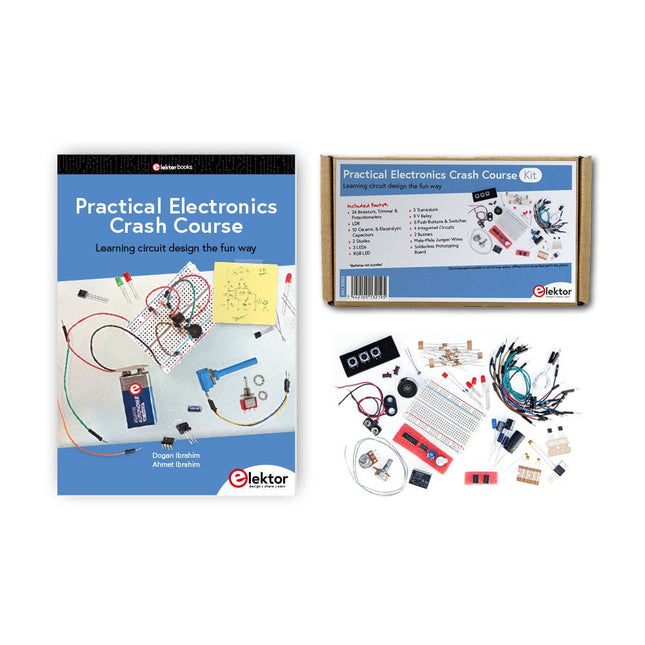
Getting started in electronics is not as difficult as you may think. With this bundle (book + kit of parts), you can explore and learn the most important electrical and electronics engineering concepts in a fun way by doing various experiments. You will learn electronics practically without getting into complex technical jargon and long calculations. As a result, you will be creating your own projects soon.
This kit contains the components required to build most of the detailed examples of the book on a breadboard and try them out for real.
The kit can, of course, also be used without the book for building other circuits and doing your own experiments.
Kit contents
1x 39 Ω, 1 W resistor
1x 47 Ω resistor
1x 180 Ω resistor
1x 330 Ω resistor
3x 1 kΩ resistor
1x 2.2 kΩ resistor
1x 3.9 kΩ resistor
1x 6.8 kΩ resistor
1x 10 kΩ resistor
1x 15 kΩ resistor
1x 22 kΩ resistor
1x 33 kΩ resistor
1x 47 kΩ resistor
1x 56 kΩ resistor
1x 82 kΩ resistor
1x 120 kΩ resistor
1x 680 kΩ resistor
2x 100 kΩ resistor
1x 10 kΩ trimmer
1x 10 kΩ linear potentiometer
1x 100 kΩ linear potentiometer
1x LDR
1x 1 nF ceramic capacitor
2x 10 nF ceramic capacitor
1x 100 nF ceramic capacitor
1x 1 µF, 25 V aluminium electrolytic capacitor
2x 10 µF, 25 V aluminium electrolytic capacitor
1x 100 µF, 25 V aluminium electrolytic capacitor
1x 470 µF, 25 V aluminium electrolytic capacitor
1x 1000 µF, 25 V aluminium electrolytic capacitor
1x RGB LED, Common-Cathode (CC)
1x 1N4148 small signal diode
1x 1N4733A 5.1 V, 1 W Zener diode
3x LED, red
2x BC337 NPN transistor
1x IRFZ44N N-channel MOSFET
2x NE555 timer
1x LM393 comparator
1x 74HCT08 quad AND gate
3x Tactile switch
2x SPDT switch
1x Relay, SPDT, 9 VDC
1x Active buzzer
1x Passive buzzer
50 cm Solid wire, 16 AWG, unjacketed
2x PP3 9 V battery clip
1x Breadboard
20x Jumper wire
This bundle contains:
Practical Electronics Crash Course Kit (valued at: €45)
Book: Practical Electronics Crash Course (normal price: €45)
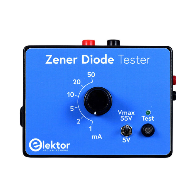
The Elektor Zener Diode Tester is essentially a constant-current source that can be switched in steps from 1 to 50 mA. It can be used to test Z-diodes up to a maximum of 54 V. Thanks to a 60-V step-up converter, the device can be powered by the usual 5 to 12 V.
The principle of this tester is straightforward. A Z-diode or other DUT (device under test, such as an LED) is biased by an adjustable current source. The voltage across the DUT can be measured with a multimeter. The voltage of most (small) Z-diodes is specified at a current of 5 mA. Depending on the application, the voltage at other currents can also be of interest. That is why six current settings are available: 1, 2, 5, 10, 20, and 50 mA. LEDs are often specified at a current of 20 mA.
What can be tested is:
Whether a Z-diode is defective (short circuit or high impedance).
Whether a Z-diode exhibits the correct Z-voltage.
How a Z-voltage changes with different currents.
What exact voltage is present at an integrated voltage reference.
Whether LEDs in a series chain differ in brightness (hence the 20 mA current).
What the current gain is for different base currents in (power) transistors.
The kit contains all parts listed in the bill of materials including PCB and enclosure.
Specifications
Supply voltage
5…12 V/2 A (USB-C)
Supply current (Itest = 50 mA)
1.1 A @ 5 V / 412 mA @ 12 V
Selectable currents
1, 2, 5, 10, 20, and 50 mA
Max. test voltage
>54 V @ Itest ≥1 mA
Max. output voltage
60 V @ Itest = 0 mA
Voltage limit at 5 V
4.5 V @ Itest = 1 mA / 5.18 V @ Itest = 50 mA
Enclosure dimensions
110 x 82 x 44 mm
PCB size
105.4 x 67.3 mm
Connections
4 mm banana sockets for multimeter
2 mm banana sockets for test clips
USB-C socket for power supply
Included
Resistors
R1 = 3.3 kΩ, 600 mW, 1%
R2 = 0.15 Ω, 1 W, 5%, LS 12.7 mm, ø 3.5 mm
R3, R8 = 180 Ω, 600 mW, 1%
R4, R6, R16 = 1 kΩ, 600 mW, 1%
R5, R19 = 47 kΩ, 600 mW, 1%
R7 = 3.9 kΩ, 1 W, 5%, LS 12.7 mm, ø 3.5 mm
R9, R10, R12 = 10 kΩ, 600 mW, 1%
R11, R13 = 100 Ω, 600 mW 1%
R14 = 249 Ω, 600 mW, 1%
R15 = 499 Ω, 600 mW, 1%
R17 = 2.49 kΩ, 250 mW, 1%
R18 = 4.99 kΩ, 250 mW, 1%
Capacitors
C1 = 470 uF / 35 V, 20%, Ir = 1.86 A, ø 12.5 mm, LS 5 mm, ESR = 0.038 Ω (Panasonic EEUTP1V471)
C2 = 1 uF / 100 V, 10%, X7R, LS 5 mm
C3 = 2.2 nF / 50 V, 10%, X7R, LS 5 mm
C4, C7 = 100 nF / 100 V, 10%, X7R, LS 5 mm
C5 = 100 uF / 100 V, 20%, ø 14 mm max., LS 5 mm
C6 = 1 nF / 100 V, 10%, X7R, LS 5 mm
Inductor
L1 = 100 uH, Irms = 2.4 A, Isat = 3.5 A, 0.09 Ω, radial, pitch 2.5/5/10 mm, ø 14 mm max. (Kemet SBC8-101-242)
Semiconductors
D1 = MUR120G, DO-41
D2, D4 = STPS3150RL, DO-201AD
D3 = Z-diode, 18 V, 1.3 W (BZX85C18)
D5 = Z-diode, 5.1 V, 0.5 W (1N5231B)
LED1 = LED in pushbutton S1
LED2 = LED, green, 3 mm
IC1 = MC34063, DIP-8
IC2 = LM4040BIZ-5.0/NOPB, TO-92 (TO-226AA-3)
IC3 = TL051CP, DIP-8
T1 = BC327.25, TO-92
T2 = STP40NF10L, TO-220
T3 = IRF9510PBF, TO-220
T4 = 2N7000, TO-92
Others
K1, K2, S1, S3 = 2-way screw terminal block, LS 3.5 mm, max. 1.5 mm²
connected to K1 = USB-C socket, 30 V/3 A, chassis mounted, wired, 9 x 16 mm
connected to K2 = Banana Connector, 2 mm, Socket, 60 VDC, Panel Mount, red (Multicomp 24.102.1)
connected to K2 = Banana Connector, 2 mm, Socket, 60 VDC, Panel Mount, black (Multicomp 24.102.2)
Test clip, red, 30 VAC/60 VDC (Hirschmann 931467101)
Test clip, black, 30 VAC/60 VDC (Hirschmann 931467100)
S1 = Pushbutton, panel mount, SPST-NO, 30 DC/100 mA, with red LED
S2 = Rotary Switch, 6 position, 2 pole, 30°, 250 V/150 mA
S3 = Toggle switch, panel mount, SPDT, solder lugs, 28 VDC
T2, T3 = Heat sink, 15°C/W, FK 214 SA-CB
Enclosure Hammond 1591XXSSBK, ABS, 110 x 82 x 44 mm
Knob for S2, round shaft 6 mm, ø 21 mm, with indicator line (Multicomp CP-LB21-6-6D)
4 x Self-tapping screw #4-1/4", carbon steel, pan head
Banana plug, red, 2 mm, 60 VDC (Multicomp 25.205.1)
Banana plug, black, 2 mm, 60 VDC (Multicomp 25.205.2)
Banana socket, black 4 mm, panel mount
Banana socket, red 4 mm, panel mount
for LED1, LED2 = Pin header, 1 x 2, vertical, pitch 2.54 mm
for LED1, LED2 = Pin socket, 1 x 2, vertical, pitch 2.54 mm
for T2, T3 = M3 screw, 10 mm, steel, pan head
2 x M3 washer, plain, steel
4 x M3 nut
for IC1, IC3 = DIP-8 socket
Wire, black, 0.25 mm² (24 AWG), stranded 14 x 0.15 mm, 1 m
Wire, red, 0.25 mm² (24 AWG), stranded 14 x 0.15 mm, 1 m
PCB 250772-1 v1.1
Links
Article
Elektor Labs
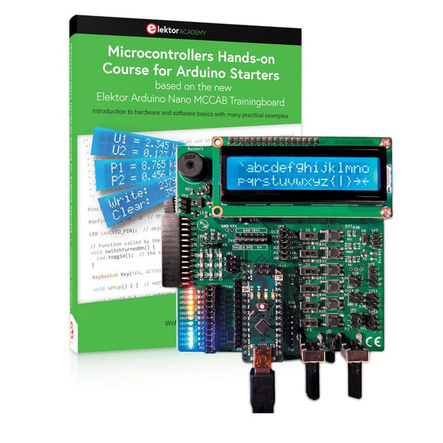
Realize your own projects with the Elektor Arduino Nano MCCAB Training Board
The microcontroller is probably the most fascinating subfield of electronics. Due to the multitude of functions, it combines on its chip, it is a universal multi-tool for developers to realize their projects. Practically every device of daily use today is controlled by a microcontroller. However, for an electronic layman, realizing his own ideas with a microcontroller has so far remained a pipe dream due to its complexity. The Arduino concept has largely simplified the use of microcontrollers, so that now even laymen can realize their own electronics ideas with a microcontroller.
Book & Hardware in the Bundle: 'Learning by Doing'
This book, which is included in the bundle, shows how you can realize your own projects with a microcontroller even without much experience in electronics and programming languages. It is a microcontrollers hands-on course for starters, because after an overview of the internals of the microcontroller and an introduction to the programming language C, the focus of the course is on the practical exercises. The reader acquires the necessary knowledge by 'learning by doing': in the extensive practical section with 12 projects and 46 exercises, what is learned in the front part of the book is underpinned with many examples. The exercises are structured in such a way that the user is given a task to solve using the knowledge built up in the theoretical part of the book. Each exercise is followed by a sample solution that is explained and commented on in detail, which helps the user to solve problems and compare it with his own solution.
Arduino IDE
The Arduino IDE is a software development environment that can be downloaded for free to your own PC and that contains the entire software package needed for your own microcontroller projects. You write your programs ('apps') with the IDE’s editor in the C programming language. You translate them into the bits and bytes that the microcontroller understands using the Arduino IDE's built-in compiler, and then load them into the microcontroller's memory on the Elektor Arduino MCCAB Nano Training Board via a USB cable.
Query or control external sensors, motors or assemblies
In addition to an Arduino Nano microcontroller module, the Elektor Arduino Nano MCCAB Training Board contains all the components required for the exercises, such as light-emitting diodes, switches, pushbuttons, acoustic signal transmitters, etc. External sensors, motors or assemblies can also be queried or controlled with this microcontroller training system.
Specifications (Arduino Nano MCCAB Training Board)
Power Supply
Via the USB connection of the connected PC or an external power supply unit (not included)
Operating Voltage
+5 Vcc
Input Voltage
All inputs
0 V to +5 V
VX1 and VX2
+8 V to +12 V (only when using an external power supply)
Hardware periphery
LCD
2x16 characters
Potentiometer P1 & P2
JP3: selection of operating voltage of P1 & P2
Distributor
SV4: Distributor for the operating voltagesSV5, SV6: Distributor for the inputs/outputs of the microcontroller
Switches and buttons
RESET button on the Arduino Nano module 6x pushbutton switches K1 ... K6 6x slide switches S1 ... S6 JP2: Connection of the switches with the inputs of the microcontroller
Buzzer
Piezo buzzer Buzzer1 with jumper on JP6
Indicator lights
11 x LED: Status indicator for the inputs/outputs LED L on the Arduino Nano module, connected to GPIO D13 JP6: Connection of LEDs LD10 ... LD20 with GPIOs D2 ... D12
Serial interfacesSPI & I²C
JP4: Selection of the signal at pin X of the SPI connector SV12 SV9 to SV12: SPI interface (3.3 V/5 V) or I²C interface
Switching output for external devices
SV1, SV7: Switching output (maximum +24 V/160 mA, externally supplied) SV2: 2x13 pins for connection of external modules
3x3 LED matrix(9 red LEDs)
SV3: Columns of the 3x3 LED matrix (outputs D6 ... D8) JP1: Connection of the rows with the GPIOs D3 ... D5
Software
Library MCCABLib
Control of hardware components (switches, buttons, LEDs, 3x3 LED matrix, buzzer) on the MCCAB Training Board
Operating Temperature
Up to +40 °C
Dimensions
100 x 100 x 20 mm
Specifications (Arduino Nano)
Microcontroller
ATmega328P
Architecture
AVR
Operating Voltage
5 V
Flash Memory
32 KB, of which 2 KB used by bootloader
SRAM
2 KB
Clock Speed
16 MHz
Analog IN Pins
8
EEPROM
1 KB
DC Current per I/O Pins
40 mA on one I/O pin, total maximum 200 mA on all pins together
Input Voltage
7-12 V
Digital I/O Pins
22 (6 of which are PWM)
PWM Output
6
Power Consumption
19 mA
Dimensions
18 x 45 mm
Weight
7 g
Included
Elektor Arduino Nano MCCAB Training Board
Arduino Nano
Book: Microcontrollers Hands-on Course for Arduino Starters
Der simpel „Stromversorgung“ genannte Schaltungsteil wird sowohl bei der Entwicklung als auch bei der Reparatur von Elektronik enorm unterschätzt. Dabei ist die Vielfalt bei Netzteilen oder neudeutsch „PSU“ enorm. Es gibt sie in den unterschiedlichsten Ausführungen: mit Gleich- oder Wechselspannung, als Generator, Akku oder Batterie, als Solar-Panel, extern oder eingebaut, linear oder „geschaltet“ – um nur einige zu nennen. Auch die Leistungsbereiche sind enorm: von Nano-Ampere bis Kilo-Ampere – dasselbe gilt für Spannungen. Bei der konkreten Umsetzung kann man zwischen ICs oder diskreten Bauteilen, zwischen fertigem Gerät bzw. Modul oder der Realisation aus selbstverlöteten Bauteilen wählen.
Dieses Special deckt die wichtigsten Merkmale und Gestaltungsaspekte von Stromversorgungen ab.
Inhalt
Grundlagen
BatteriemanagementWas man beim Einsatz von (Lithium-)Akkus beachten muss.
Festspannungsnetzgerät mit LinearreglerDas beste Ergebnis gleich nach den Batterien.
Lichtenergie sammelnWie man ein Solarmodul für ein Energy-Harvesting-Projekt verwenden kann.
Netzbetriebene VersorgungsgeräteBasis-schaltungen und Tipps für Transformatoren, Gleichrichtung, Siebung und Stabilisierung.
SanftanlaufDer hohe Einschaltstrompuls sollte vermieden werden.
Steuerbare GleichrichterEinige Vorschläge um die Verlustleistung im Längsregler möglichst gering zu halten.
Komponenten
Arbeitsblatt: Spannungsreglerserie LM117 / LM217 / LM317
Supercaps
Reviews
Labornetzteil-Kit Joy-iT RD6006
Elektronische Last Siglent SDL1020X-E
Projekte
Balkon-KraftwerkSelbst installiert = schnell amortisiert!
DIY-LiPo-Supercharger-KitVom Prototyp zum Massenmarkt.
Doppelanoden-MOSFET-ThyristorSchneller und effizienter als herkömmliche SCRs.
Batterie-EntsafterNicht wegwerfen, ausquetschen!
Hochspannungsnetzteil mit KennlinienschreiberSpannungen bis 400 V einstellen und Kennlinien für Röhren und Transistoren erstellen.
HochspannungsnetzteilFür RIAA-Röhrenvorverstärker und andere Anwendungen.
MicroSupplyEine Laborstromversorgung für universelle Anwendungen.
Phantom-Speisung mit geschalteten KondensatorenSpannungsverdreifachung mit zwei ICs.
Das SMPS800RE Schaltnetzteil für den Elektor Fortissimo-100Zuverlässig, leicht und erschwinglich.
SoftstartSchont das Netzgerät und die Last.
UniLab 2Geschaltetes Labornetzteil 0…30 V/3 A
Tipps
Softstart für Step-Down-Schaltregler
Stromabschaltung mit minimalen Verlusten
Powerbank-Geheimnisse
Künstliche Masse
Akku-Erfrischer
Akkupack-Entlader
Parallelschaltung von Spannungsreglern
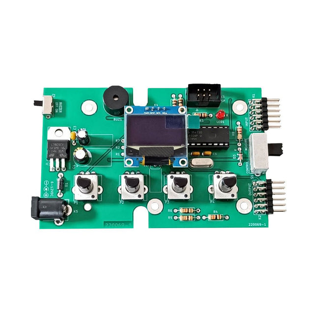
The Elektor Super Servo Tester can control servos and measure servo signals. It can test up to four servo channels at the same time.
The Super Servo Tester comes as a kit. All the parts required to assemble the Super Servo Tester are included in the kit. Assembling the kit requires basic soldering skills. The microcontroller is already programmed.
The Super Servo Tester features two operating modes: Control/Manual and Measure/Inputs.
In Control/Manual mode the Super Servo Tester generates control signals on its outputs for up to four servos or for the flight controller or ESC. The signals are controlled by the four potentiometers.
In Measure/Inputs the Super Servo Tester measures the servo signals connected to its inputs. These signals may come from for instance an ESC, a flight controller, or the receiver or another device. The signals are also routed to the outputs to control the servos or the flight controller or ESC. The results are shown on the display.
Specifications
Operating modes
Control/Manual & Measure/Inputs
Channels
3
Servo signal inputs
4
Servo signal outputs
4
Alarm
Buzzer & LED
Display
0.96' OLED (128 x 32 pixels)
Input voltage on K5
7-12 VDC
Input voltage on K1
5-7.5 VDC
Input current
30 mA (9 VDC on K5, nothing connected to K1 and K2)
Dimensions
113 x 66 x 25 mm
Weight
60 g
Included
Resistors (0.25 W)
R1, R3
1 kΩ, 5%
R2, R4, R5, R6, R7, R9, R10
10 kΩ, 5%
R8
22 Ω, 5%
P1, P2, P3, P4
10 kΩ, lin/B, vertical potentiometer
Capacitors
C1
100 µF 16 V
C2
10 µF 25 V
C3, C4, C7
100 nF
C5, C6
22 pF
Semiconductors
D1
1N5817
D2
LM385Z-2.5
D3
BZX79-C5V1
IC1
7805
IC2
ATmega328P-PU, programmed
LED1
LED, 3 mm, red
T1
2N7000
Miscellaneous
BUZ1
Piezo buzzer with oscillator
K1, K2
2-row, 12-way pinheader, 90°
K5
Barrel jack
K4
1-row, 4-way pin socket
K3
2-row, 6-way boxed pinheader
S1
Slide switch DPDT
S2
Slide switch SPDT
X1
Crystal, 16 MHz
28-way DIP socket for IC2
Elektor PCB
OLED display, 0.96', 128 x 32 pixels, 4-pin I²C interface
Links
Elektor Magazine
Elektor Labs
Umfassendes Buch-Hardware-Bundle für den RP2040-Mikrocontroller mit über 80 Projekten
Entdecken Sie in diesem Bundle das Potenzial der modernen Controller-Technologie mit dem Raspberry Pi Pico. Das leicht verständliche Handbuch eignet sich sowohl für Anfänger als auch für erfahrene Benutzer und führt Sie von den Grundlagen der Elektronik bis hin zu den komplexen Aspekten der digitalen Signalverarbeitung. Mit dem Raspberry Pi Pico, dem speziellen Hardware-Kit und der MicroPython-Programmierung lernen Sie die wichtigsten Prinzipien des Schaltungsdesigns, der Datenerfassung und -verarbeitung.
Machen Sie praktische Erfahrungen mit über 80 Projekten wie einer Stoppuhr mit OLED-Display, einem Laser-Entfernungsmesser und einem servogesteuerten Lüfter. Diese Projekte sollen Ihnen helfen, das Gelernte in realen Szenarien anzuwenden. Das Buch behandelt auch fortgeschrittene Themen wie drahtlose RFID-Technologie, Objekterkennung und Sensorintegration für die Robotik.
Ganz gleich, ob Sie Ihre Kenntnisse in der Elektronik erweitern oder tiefer in eingebettete Systeme eintauchen möchten, dieses Bundle ist die perfekte Ressource, um das volle Potenzial des Raspberry Pi Pico zu erkunden.
Inhalt des Bundles
1x Projektbuch (287 Seiten)
1x Smart Car Kit
Bauteile
2x Lötfreies Steckbrett (400 Löcher)
1x Lötfreies Steckbrett (170 Löcher)
5x bunte 5-mm-LEDs (Grün, Rot, Blau, Gelb und Weiß)
1x Lasersender
1x Passiver Summer
1x Micro-USB-Kabel (30 cm)
1x 65 Überbrückungskabel
1x 20 cm männlicher auf weiblicher Dupont-Draht
1x Transparentes Gehäuse
1x Magnet (Durchmesser: 8 mm, Dicke: 5 mm)
1x Drehpotentiometer
10x 2 KΩ Widerstände
2x M2, 5x30 mm Kupfersäulen
10x Kreuzschlitz-Flachkopfschrauben
10x M2,5 Sechskantmuttern aus Nickel
1x 2-Zoll-Mehrzweckschraubendreher
Module
1x RGB-Modul
1x 9G-Servo
1x Dual-Achsen-XY-Joystick-Modul
1x RC522 RFID-Modul
1x 4-Bit-Digital-LED-Display-Modul
1x Ampel-Anzeigemodul
1x Drehgebermodul
1x 1602 LCD-Anzeigemodul (blau)
1x Fotowiderstandsmodul
1x Gleichstrommotor mit männlichem Dupont-Kabel
1x Lüfterflügel
1x Regentropfen-Modul
1x OLED-Modul
1x Membranschalter-Tastatur
1x Mini-Magnetfedermodul
1x Infrarot-Fernbedienung
1x Infrarot-Empfängermodul
1x DC-Schrittmotor-Treiberplatine
1x Button
Sensoren
1x Vibrationssensor
1x Bodenfeuchtesensor
1x Schallsensor
1x Mini-PIR-Bewegungssensor
1x Temperatur & Feuchtigkeitssensor
1x Flammensensor
2x Crash-Sensor
2x Tracking-Sensor
1x Ultraschallsensor
A Hands-on Guide to Crafting Your Own Power Plant
The book you are about to read provides a step-by-step guide for building a renewable energy power plant at home. Our goal was to make the book as practical as possible. The material is intended for immediate application with a small amount of theory. Yet, the theory is important as a foundation that saves time and effort by disabusing the readers of potential misconceptions. Specifically, upon having a firm understanding of photovoltaic physics, you will not be inclined to fruitlessly search for 90% efficient solar panels!
We want our readers to be the “doers”. If the book gets covered in grime and some pages become torn while you are building your power plant – this is the best compliment to us. The book covers solar and wind energy. Also, a curious power source based on manure is discussed as well, giving the doers an opportunity to further develop the manure fuel cell.
It is important to note that there are many companies offering installation of complete solar solutions. Upon installing the panels, the system is not owned by the customer. Therefore, there is no freedom for experimentation and optimization. Also, none can beat the cost of a DIY solution as well as the ultimate satisfaction.
All that is written here is a result of us building a renewable energy solution in Southern California. As the book was completed, the energy began flowing!
Multilingual DIY Kit (incl. 27 RGB LEDs + Raspberry Pi Pico)
Bring some engineering magic to your festive season with the Wordy LED Christmas Tree, a unique DIY electronics kit designed by Elektor. This beautifully engineered 3D Christmas tree combines eleven PCBs, a Raspberry Pi Pico, and 27 addressable RGB LEDs to illuminate Christmas greetings in seven languages: Danish, Dutch, English, French, German, Italian, and Spanish.
Unlike ordinary LED trees, each word inside the tree has its own light chamber, creating a refined, softly glowing display without sound or flicker. The LEDs are fully WS2812-compatible and driven via the popular Adafruit NeoPixel library, making custom animations and color effects easy to create.
Perfect for makers, tinkerers, and festive electronics fans, this kit offers both an enjoyable build and a striking, conversation-worthy decoration. The Wordy Christmas Tree is your perfect holiday maker project!
Features
Multilingual greetings (7 languages) milled into the front panel
3D construction from 11 interlocking PCBs
Powered by Raspberry Pi Pico
27 individually addressable RGB LEDs (pre-mounted)
Smooth fade-in and fade-out animations
Fully programmable using the Arduino IDE
A 5-V power supply (with micro-USB connector) capable of ≥1 A is recommended for maximum brightness (not included)
Dimensions (H x W x D): 130 x 115 x 75 mm
Included
All required PCBs with LEDs and other SMD parts mounted
Raspberry Pi Pico (to be soldered & programmed by the user)
3-way pin header (to be soldered by the user)
3-way pin socket (to be soldered by the user)
4x Self-adhesive dome bumpers
Project Page
Elektor Labs
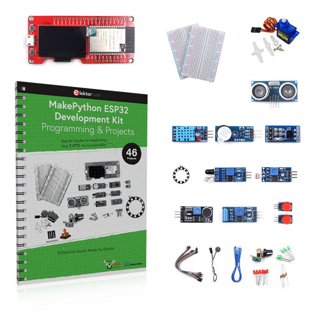
Learn how to use the ESP32 Microcontroller and MicroPython programming in your future projects!
The project book, written by well-known Elektor author Dogan Ibrahim, holds many software- and hardware-based projects especially developed for the MakePython ESP32 Development Kit. The kit comes with several LEDs, sensors, and actuators. The kit will help you acquire the basic knowledge to create IoT projects.
The book’s fully evaluated projects feature all the supplied components. Each project includes a block diagram, a circuit diagram, a full program listing, and a complete program description.
Included in the kit
1x MakePython ESP32 development board with LCD
1x Ultrasonic ranging module
1x Temperature and humidity sensor
1x Buzzer module
1x DS18B20 module
1x Infrared module
1x Potentiometer
1x WS2812 module
1x Sound sensor
1x Vibration sensor
1x Photosensitive resistance module
1x Pulse sensor
1x Servo motor
1x USB cable
2x Button
2x Breadboard
45x Jumper wire
10x Resistor 330R
10x LED (Red)
10x LED (Green)
1x Project book (206 pages)
46 Projects in the Book
LED Projects
Blinking LED
Flashing SOS
Blinking LED – using a timer
Alternately flashing LEDs
Button control
Changing the LED flashing rate using pushbutton interrupts
Chasing-LEDs
Binary-counting LEDs
Christmas lights (random-flashing 8 LEDs)
Electronic dice
Lucky day of the week
Pulsewidth Modulation (PWM) Projects
Generate a 1000-Hz PWM waveform with 50% duty cycle
LED brightness control
Measuring the frequency and duty cycle of a PWM waveform
Melody maker
Simple electronic organ
Servo motor control
Servo motor DS18B20 thermometer
Analog To Digital Converter (ADC) Projects
Voltmeter
Plotting the analog input voltage
ESP32 internal temperature sensor
Ohmmeter
Photosensitive resistance module
Digital To Analog Converter (DAC) Projects
Generating fixed voltages
Generating a sawtooth-wave signal
Generating a triangular-wave signal
Arbitrary periodic waveform
Generating a sinewave signal
Generating accurate sinewave signal using timer interrupts
Using The OLED Display
Seconds counter
Event counter
DS18B20 OLED based digital thermometer
ON-OFF temperature controller
Measuring the temperature and humidity
Ultrasonic distance measurement
Height of a person (stadiometer)
Heart rate (pulse) measurement
Other Sensors Supplied with the Kit
Theft alarm
Sound-activated light
Infrared obstacle avoidance with buzzer
WS2812 RGB LED ring
Timestamping temperature and humidity readings
Network Programming
Wi-Fi scanner
Remote control from the Internet browser (using a smartphone or PC) – Web Server
Storing temperature and humidity data in the Cloud
Low-Power Operation
Using a timer to wake up the processor
Open-Source-Code mit Arduino IDE und PlatformIO
Autonomes Fahren: GPS, Accelerometer, Gyroskop
PS3-Controller
Mikrocontroller wie der Arduino und Einplatinenrechner wie der Raspberry Pi haben sich zu beliebten Komponenten entwickelt. Dritter im Bunde ist der ESP32 der Firma Espressif. Mikrocontroller dieser Baureihe zeichnen sich durch eine Vielzahl implementierter Funktionen aus, die bei einem Arduino konventioneller Prägung mit einem Atmel-AVR-Mikrocontroller erst mit weiterer Hardware möglich sind. Prominentes Beispiel sind hier die WiFi- und Bluetooth-Funktionalitäten. Gegenüber einem Raspberry Pi zeichnen sie sich durch einen deutlich geringeren Preis aus.
Allgemeine Informationen für die Realisierung eines Roboterauto-Projekts mit dem ESP32 sind leicht zu finden. Dabei handelt es sich aber oft nur um Ausführungen zu einem Teilaspekt, ohne inhaltliche oder funktionale Abstimmung. So ist nicht nur die Beschaffung der benötigten Informationen mühselig und zeitaufwändig, sie kann auch außerordentlich fehlerträchtig sein.
Ansatzpunkt dieses Buches ist, diese Lücke zu schließen. Es geht auf verschiedene Möglichkeiten eines Chassis ein, vermittelt nötige Kenntnisse und führt schrittweise von einer einfachen Motorsteuerung zu einem komplexen sensor- und sprachgesteuerten Roboterauto. Hacks rund um GPS und eine PlayStation 3 runden die Sache ab.
Inhalt
Bei der Reihenfolge der Kapitel wurde versucht – beginnend bei der Darstellung von grundlegenden Informationen – über die Lösung einfacher Aufgaben zu etwas anspruchsvolleren Techniken zu führen.
Der Mikrocontroller ESP32
Die Software erstellen
Die Stromversorgung
Rund um die Hardware
Das Chassis
Der Gleichstrommotor
Kabellose Steuerung über WiFi
Mit Sensoren Hindernisse erkennen
Eine eigene Roboterauto-App
Servo und Lichtsensor
GPS
Accelerometer / Gyroskop
PS3-Controller
Roboterauto-App
Hinweis zur Software
Die Dateien haben das Suffix (.cpp). Grund ist die Entwicklung mit PlatformIO. Mit Copy & Paste sollten sie auch in der Arduino-IDE verwendet werden können.
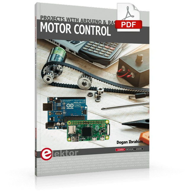
This book is about DC electric motors and their use in Arduino and Raspberry Pi Zero W based projects. The book includes many tested and working projects where each project has the following sub-headings:
Title of the project
Description of the project
Block diagram
Circuit diagram
Project assembly
Complete program listing of the project
Full description of the program
The projects in the book cover the standard DC motors, stepper motors, servo motors, and mobile robots. The book is aimed at students, hobbyists, and anyone else interested in developing microcontroller based projects using the Arduino Uno or the Raspberry Pi Zero W.
One of the nice features of this book is that it gives complete projects for remote control of a mobile robot from a mobile phone, using the Arduino Uno as well as the Raspberry Pi Zero W development boards. These projects are developed using Wi-Fi as well as the Bluetooth connectivity with the mobile phone. Readers should be able to move a robot forward, reverse, turn left, or turn right by sending simple commands from a mobile phone. Full program listings of all the projects as well as the detailed program descriptions are given in the book. Users should be able to use the projects as they are presented, or modify them to suit to their own needs.
ÉLECTRICITÉ PHOTOVOLTAÏQUE = ÉLECTRICITÉ GRATUITE
Nous sommes désormais plus qu'heureux de poursuivre nos recherches sur notre propre autonomie et de veiller à ce que notre production électrique photovoltaïque soit appropriée ! D'abord on en rêve, puis vient l'étape du calcul : comparer le coût du kilowattheure d'origine du nucléaire (environnement à partir de centimes d'euro) et le calcul du kilowattheure d'origine photovoltaïque (l'environnement de 22 centimes de l'euro*), et nous saurons où en sont nos motivations d'écocitoyens.
Gérard Guihéneuf, l'auteur de ce nouveau livre, pense qu'il ne faut pas se contenter d'aligner chiffres et idées. La nouvelle approche du processus de création d'entreprise se base sur la compréhension et les dimensions des installations des bâtiments domestiques dans le domaine public en 2009 et sur l'actualité des techniques et pratiques de réponse aux questions qui se posent lors de l'électrification des le site isolé !
La conception de projets simples, comme un contexte domestique, et d'un commentaire électrique standard, comme un système d'énergie photovoltaïque, trois emplacements réguliers : un abri dans le jardin, un garage et un mobil-home.
L'économie est spectaculaire lorsqu'il s'agit de composants électroniques et d'assemblages de certains constituants essentiels, car les régulateurs de charge, les onduleurs et les panneaux solaires ne suffisent pas à l'entretien autonome du site. Si vous souhaitez en savoir plus sur l'électrification professionnelle de votre chantier, vous pouvez en savoir plus sur les dimensions des éléments constitutifs sans sacrifier l'efficacité !
Vous pouvez également utiliser la copie du Gerber et du Sprint Layout pour les circuits imprimés de la livrée.
*avec les batteries en cours de reconditionnement lors de la panne photovoltaïque en cours et dans les vingt-cinq