
Search results for "enviro or environmental or monitoring or station or for or rpi"
-

Elektor Digital Elektor 07-08/2024 (PDF)
Diese Ausgabe steht allen GOLD- und GREEN-Mitgliedern auf der ElektorMagazine-Website zum Download bereit! Sie sind noch kein Mitglied? Hier klicken! Kleine WärmebildkameraRealisiert mit einem Arduino UNO Projekt-Update #3: Energiemessgerät mit ESP32Integration und Test mit Home Assistant 2024: Eine Odyssee in die KIVerbessern der Objekterkennung: Nutzung verfeinerter Techniken Raspberry Pi Goes KINeues Kit enthält M.2-HAT mit KI-Beschleuniger Sensoren für WetterstationenWelchen Sensor sollte man wählen? KI-gestützter WasserzählerTeil 1: Bringen Sie Ihren alten Zähler ins IoT! Ein GSM-AlarmNutzung der GSM-Technologie für die Fernüberwachung von Garagen Low-Power-Thread-Geräte optimiert und getestetNiedriger Energiebedarf ... Niedrige Leistung? Aus dem Leben gegriffenDer Gender-Gap Nebelkammer selbstgebautUnsichtbare Strahlung sichtbar machen SparkFun Thing Plus MatterEin vielseitiges Matter-basiertes IoT-Entwicklungsboard IoT-RetrofittingRS232-Geräte fit für Industrie 4.0 machen IoT mit 8-Bit-Mikrocontrollern Technologie als Motor der NachhaltigkeitNeuerungen führen zu Energieeffizienz in vielen Applikationen AWS für Arduino und Co.Teil 1: AWS-IoT-ExpressLink in der Praxis Luftstromdetektor (nur) mit ArduinoKeine externen Sensoren erforderlich! WasserleckdetektorVerbunden mit der Arduino-Cloud QuarzeBemerkenswerte Bauteile Universeller Garten-LoggerEin Schritt auf dem Weg zur KI-gestützten Gartenarbeit Analoger 1-kHz-GeneratorSinuswellen mit geringen Verzerrungen Miletus: Web-Apps offline nutzenSystem- und Gerätezugriff inklusive Von 4G zu 5GIst es wirklich so einfach? Aller Anfang...muss nicht schwer sein: Der Ausgleich
€ 11,90
-

Elektor Digital Intelligente Sensoren in Embedded-Systemen (PDF)
Vom Messwert zur stabilen Entscheidung Wie wird aus einem einfachen Mikrocontroller ein intelligentes System, das Sensorwerte erfasst, verarbeitet und sinnvoll darauf reagiert? Dieses Buch zeigt es Ihnen Schritt für Schritt – verständlich, praxisnah und ohne unnötige Vorkenntnisse. Sie beginnen mit den Grundlagen der digitalen und analogen Ein- und Ausgänge. Anschließend lernen Sie, wie Sensorwerte gelesen, geglättet und zuverlässig bewertet werden. Anschauliche Beispiele erklären, warum einzelne Messwerte oft täuschen können und wie Mittelwertbildung, Hysterese und einfache Entscheidungsregeln für stabile Ergebnisse sorgen. Nach und nach erweitern Sie Ihre Projekte um Displays, I²C-Kommunikation und mehrere vernetzte Mikrocontroller. So entstehen verteilte Systeme, in denen Raspberry Pi Pico und ATtiny-Controller Daten austauschen und gemeinsam Aufgaben übernehmen. Im fortgeschrittenen Teil erhalten Sie einen leicht verständlichen Einstieg in Merkmalsbildung, Datenvorverarbeitung, hybride Entscheidungsmodelle und TinyML-nahe Anwendungen. Dabei verbinden Sie klassische Regelungstechnik mit modernen datenbasierten Methoden. Alle Projekte werden von ausführlich kommentierten Programmen in C und MicroPython begleitet. Das Buch richtet sich an Einsteiger, Maker, Studierende und alle, die Embedded-Systeme von Grund auf verstehen möchten. Am Ende können Sie eigene Systeme entwickeln, die nicht nur messen, sondern Informationen auswerten, zuverlässige Entscheidungen treffen und gezielt reagieren.
€ 32,80
Members: € 29,52
-

JOY-iT Joy-Pi Advanced Development Platform (incl. Raspberry Pi 4, 8 GB)
The Joy-Pi Advanced is a compact and powerful device that allows you to realize your projects quickly and easily. Whether you already have a lot of experience, or next to none, the Joy-Pi Advanced lets you unleash your creativity. Thanks to its compatibility with a wide range of platforms, including Raspberry Pi, Raspberry Pi Pico, Arduino Nano, BBC micro:bit, and NodeMCU ESP32, you can easily and quickly access your preferred platform. In addition, the Joy-Pi Advanced features more than 30 stations, lessons, and modules, giving you an unlimited variety of ways to get your projects done. With the self-developed learning center, you can not only improve your skills but also create new projects. The learning center offers a wealth of information and tutorials that will guide you step by step through your projects. Joy-Pi Advanced is characterized in particular by its intelligent switch units, which allow an extended use of the available pins. A total of three switch units are integrated, each equipped with 12 individual switches that provide precise control of the connected sensors and modules. This system solves the well-known problem of limited pin count that occurs with conventional microcontrollers. The switch units allow you to operate a large number of sensors and modules in parallel by switching them on and off individually. This simulates multiple pin assignment, allowing you to exploit the full power of your projects without compromising functionality. By combining innovative adapter boards and the micro:bit slot, you can achieve seamless compatibility with a wide range of microcontrollers such as Raspberry Pi Pico, NodeMCU ESP32, micro:mit and Arduino Nano. The specially developed adapter boards are designed to perfectly match the respective microcontroller. By plugging the microcontroller onto the appropriate adapter board and then plugging it into the micro:bit slot, the Joy-Pi Advanced quickly and easily becomes compatible with the different microcontrollers. This allows seamless integration of your preferred platform and the ability to combine the strengths of the different microcontrollers in your projects. This way, you can fully focus on your creative projects without worrying about the compatibility of different microcontrollers. The Joy-Pi Advanced simplifies the development process and gives you the possibility to design your projects flexibly and individually. Features Highly integrated development platform & learning center Fast, easy & wireless combination of various sensors & actuators Installation option for Raspberry Pi 4 Compatible with various microcontrollers Self-developed, didactic learning platform for Raspberry Pi & Windows Specifications Compatible to Raspberry Pi 4, Arduino Nano, NodeMCU ESP32, BBC micro:bit, Raspberry Pi Pico Installed sensors, actuators & components 39 Learning platform Over 40 entries in the know-ledge database, 10 projects, 10 learning tasks, 14 visions Displays 7-segment display, 16x2 display, 1.8“ TFT display, 0.96" OLED display, 8x8 RGB matrix Sensors DS18B20, shock sensor, hall sensor, barometer, sound sensor, gyroscope, PIR sensor, Light barrier, NTC, Light sensor, 6x touch sensor, color sensor, ultrasonic distance sensor, DHT11 temperature & humidity sensor Control Joystick, 5x switches, potentiometer, rotary encoder, 4x4 button matrix, relays, PWM fan Motors Servo interface, Stepper motor interface, Vibration motor Measuring & conversion modules Analog-Digital Converter, Level converter, voltmeter, Variable voltage supply Other components RTC real time clock, buzzer, EEPROM memory, infrared receiver, breadboard, RFID reader Adapter boards Adapter for NodeMCU ESP32, Arduino Nano & Raspberry Pi Pico, Board connectors for Raspberry Pi & External Boards Electronic components Infrared remote control, RFID chip, RFID card, 6x alligator clips, microSD card reader, servo motor, stepper motor, 32 GB microSD card Components 40x resistors, 3x green LEDs, 3x yellow LEDs, 3x red LEDs, 1x transistor, 5x buttons, 1x potentiometer, 2x capacitors Other accessories Screw assortment, screwdriver, accessory storage bag, power supply & power cable, servo mount Power supply Built-in power supply: 36 W, 12 V, 3 A Case connector: Small device plug C8 Voltage outputs 12 V, 5 V, 3.3 V, Variable voltage output (2-11 V) Data buses & signal outputs I²C, SPI, Analog to digital converter Battery (RTC) CR2032 Dimensions 327 x 200 x 52 mm Included Raspberry Pi 4 (8 GB RAM) Downloads Joy-Pi website Datasheet Manual
€ 529,00€ 469,00Best Price
-

Elektor Labs Elektor Low-Noise Lab Power Supply
The Elektor Low-Noise Lab Power Supply is a fully analogue, adjustable, medium-power symmetrical bench supply that contains no switching or digital components. It provides an output voltage adjustable between 0 V and ±22 V, and an output current adjustable from 0 A to 1 A. Because it avoids any form of switching circuitry, the design delivers extremely low noise. To display both output voltages and currents, four miniature moving-coil panel meters are used. Most modern laboratory power supplies and AC adapters employ switch-mode techniques. Even the best examples inevitably exhibit high-frequency ripple and other switching artefacts on their output, which can interfere with the testing of sensitive analogue circuits and disturb low-level measurements. To overcome this, the concept here is a completely analogue power supply. Although less efficient than its switch-mode counterparts, the reduced efficiency is of little importance for test-bench use and ensures cleaner, more reliable measurement results. Because many analogue circuits require a symmetrical supply, this design delivers positive and negative output voltages of equal magnitude. A small amount of adjustment is available to compensate for any imbalance. Naturally, a variable current-limit function is also included. The kit includes the components required to build the power supply, except for the transformers. Specifications Output Voltage 0…+22 V, 0, −22 V Output Current 0…+1 A, 0…−1 A Noise −85 dBV, (at 0.95 A/20 V, B = 22 kHz) −84 dBV (at 0.95 A/20 V, B > 500 kHz) Ripple 50 µVRMS (at 950 mA/20 V, B = 22 kHz, mainly 100 Hz component) Included 3x PCBs: Regulator (PCB-1), Mains Filter (PCB-2) and Transformer (PCB-3) All the components except the AC transformers 4x moving-coil meters Additional parts for wiring (wires, banana sockets, IEC Power entry module, etc.) Not included The three AC transformers An enclosure Parts List For the Regulator PCB (240386-1) Resistors (250 mW, 1%) R1 = 12 Ω R2, R8, R37, R62 = 1 MΩ R3, R7, R10, R13, R17, R20, R22, R30, R35, R42, R45, R47, R55, R60 = 100 Ω, 600 mW R4, R5 = 4.7 kΩ R6 = 100 kΩ R9, R12, R14, R36, R38, R39, R61, R63, R66, R72, R78, R79 = 10.0 kΩ, 600 mW R11 = 9.76 kΩ, 600 mW R15, R40 = 44.2 kΩ, 600 mW R16, R41, R77 = 1 kΩ R18, R43 = 1.5 kΩ, 1 W, 5% R19, R44 = 470 Ω, 1 W, 5% R21, R46 = 330 Ω, 600 mW R23, R24, R48, R49 = 1.0 Ω, 1 W R25, R50 = 1 kΩ, 1 W, 5% R26, R28, R51, R53 = 1.000 kΩ 0.1%, 15 ppm/C R27, R29, R52, R54 = 10.00 kΩ 0.1%, 15 ppm/C R31, R56 = 1.2 kΩ, 1 W, 5% R32, R57 = 47 kΩ R33, R58 = 270 Ω R34, R59 = 27 kΩ R64, R69 = 12.0 kΩ R65 = 3.0 kΩ, 600 mW R67, R80 = 470 Ω, 600 mW R68, R70 = 6.8 kΩ, 600 mW R71 = 30.0 kΩ,, 600 mW R73, R74, R75, R76 = 10 MΩ P1, P2, P3 = 10 kΩ, 200 mW, 20%, potentiometer, 1 turns, single, lin., panel mount P4, P5 = 500 Ω, 500 mW, 10%, trimmer, 25 turns, 3296Y-1-501LF Bourns P6, P7 = 10 kΩ, 500 mW, 10%, trimmer, 25 turns, 3296Y-1-501LF Bourns Capacitors C1 = 100 nF, 50 V, 10%, ceramic X7R, LS 5 mm C2, C3, C6, C7, C30 = 10 µF, 63V, 20%, LS 2.5 mm, 3000hours@105°C C4, C5, C8, C9, C13, C14, C18, C19, C23, C24, C28, C29, C31, C32, C38, C39 = 100 nF, 250 V, 10%, PET, LS 7.5 mm C10, C20 = 47 nF, 100 V, 5%, PET, LS 5 mm C11, C21 = 10 nF, 100 V, 5%, PET, LS 5 mm C12, C22 = 220 µF, 35 V, 20%, 0.024 Ω, LS2.5/3.5 mm, Ir 3.4 A, 2000hours@125°C, polymer C15, C25 = 120 µF, 50 V, 20%, ESR 0.02 Ω, Diam. 10 mm max., LS 5 mm C16, C26 = 15 nF, 100 V, 5%, PET, LS 5 mm C17, C27 = 47 nF, 100 V, 5%, PET, LS 5 mm C33, C34 = 22 µF, 50 V, 20%, LS 2 mm, 10000 hours @ 105°C C35, C36, C44, C45 = 1 µF, 100 V, 10%, LS 5 mm, ceramic X7R C37 = 100 uF, 50 V, 20%. LS 3.5 mm C40, C41, C42, C43, C46, C47, C48, C49 = 1000 µF, 50 V, 20%, LS 5/7.5 mm, Ir 3.32 A, 10000hours@105°C, D 16 mm C50, C51, C52, C53 = 47 nF, 100 V, 10%, ceramic X7R, LS 5 mm Inductors L1, L2 = 4.7 µH, 3.2 A, 0.033 Ω, LS 5 mm, RLB0914-4R7ML Bourns L3 = Commom mode choke, 14.5 mH, 3 A, SSRH24NH-30145 Kemet Semiconductors D1, D2, D3, D4, D5, D9, D10, D11, D15 = BAT85, DO-34 D6, D7, D12, D13 = SR560, DO-201AD D8, D14, D16 = 1N4148, DO-35 D17 = Zenerdiode, 5.6 V, 0.5 W, DO-41 D18, D19 = 1N4004, DO-41 D20, D21 D22, D23 = V30100CI-M3/P, dual common cathode, TO-220 D24 = Zener diode, 30 V, 1 W, DO-41 LED1, LED2 = LED, red, T-1 (3 mm) LED3, LED4 = LED, green, T-1 (3 mm) TVS1, TVS2 = BZW50-33B, R6 T1, T2, T4 = BC337.25, TO-92 T3 = NJW0302G, TO-3P T5, T6, T8 = BC327.25, TO-92 T7 = NJW0281G, TO-3P T9 = BD139, TO-126 (SOT-32) IC1 = LM334Z, TO-92 IC2 = LM4040AIZ-5.0/NOPB, TO-92 (TO-226AA-3) IC3, IC4 = OPA2992IDR, SOIC-8 IC5, IC6 = OPA4992IDR, SOIC-14 IC7 = OPA992IDBVR, SOT-23-5 IC8 = LM339N, DIP-14 IC9 = LM317, TO-220 IC10 = LM337, TO-220 Others F1, F2 = 5×20 mm fuse, 1.6 A, fast acting HS1, HS2 = Heatsink MC33271 (for T3/T7), 2.7°C/W, PCB mount, height 63.5 mm K1, K4 = 3-way screw terminal block, LS 3.5 mm, max. 1.5 mm² K2, K3 = 3-way screw terminal block, LS 3.5 mm, max. 1 mm² M1, M3 = Moving coil meter, Range 30 V, type 91C4, 45×45 mm M2, M4 = Moving coil meter, Range 1 A, type 91C4, 45×45 mm² RE1 = Relay DPDT,5V, UA2-5NU Miscellaneous 3× 3-way screw terminal block, LS 3.5 mm, max. 1 mm² (for P1, P2, P3) 4× Pin header, 1×2, vertical, pitch 2.54 mm (for LED1, LED2, LED3, LED4) 4× Pin socket, 1×2, vertical. pitch 2.54 mm (for LED1, LED2, LED3, LED4) 2× Heatsink FK222SA220, 20°C/W, PCB mount (for IC9 & IC10) 2× Mica thermal pad for TO-220, 12×18×0.05 mm (for IC9 & IC10) 2× Insulating bushing IB 6, TO-220 (for IC9 & IC10) 2× Ceramic thermal pad, 23×20×2 mm (for T3 & T7) 2× PCB Fuse Holder, for 5×20 mm fuse, 10 A (for F1, F2) 2× Cover for PCB Fuse Holder, transparent (for F1, F2) 2× 2-way screw terminal block, LS 3.5 mm, max. 1 mm² (for M1 & M3) 2× 2-way screw terminal block, LS 3.5 mm, max. 1.5 mm² (for M2 & M4) 8× M3 solder lug, thickness 0.35 mm (for M1…M4) M4 solder lug, thickness 0.35 mm (to connect 4 mm banana connectors) Screened cable, 1 pair, 2×24 AWG/0.22 mm², 1 m (for P1, P2 & P3) IC socket, DIP, 14 contacts (for IC8) M3 washer, plain, steel M3 screw, 16 mm, steel, pan head M3 nut M3 spring washer 50 mm M3 standoff, steel, male-female 12 mm M3 standoff, steel, male-female 10 mm M3 standoff, steel, male-female M3 screw, 8 mm, steel, pan head For the Mains Fiter PCB (240386-2) Resistor R1 = 220 kΩ, 1 W, 500 V, 5% Capacitors C1, C2 = 470 nF, 305 VAC, Class X2, 11 × 27 mm max., LS 15/22.5 mm C3, C4, C5, C6 = 2.2 nF, 300 VAC, Class Y2, 13 × 4 mm, LS 10 mm, PP Inductors L1, L2 = Common-mode choke, 6.8 mH, 1.7 A, TDK B82732R2172B030 Semiconductor MOV1 = TVS varistor, 300 VAC, S14K300 (230 VAC, B72214S0301K101) and SK14K150 (150 VAC, B72214S0151K101) Others K1, K2 = 3-way screw terminal block, LS 7.62 mm F1 = Time-delay fuse, 0.5 A (230 VAC) or 1 A (115 VAC) Miscellaneous 1× Fuse holder, 5×20 mm, 10 A, 500 VAC 1× Transparent fuse cover 4× 10 mm M3 standoff, steel, male–female 4× M3 screw, 8 mm, steel, pan head 4× M3 nut For the Transformer PCB (240386-3) Resistors R1, R2 = 2.7 kΩ, 600 mW, 1% R3 = 10.0 kΩ, 600 mW, 1% Capacitor C1 = 220 µF, 50 V, 20%, Ø10 mm, LS 5 mm, 4000 h @ 105°C Transformers (not included in this kit!) TR1, TR2, TR3 = 2×7 V, 25 VA, PCB-mounted toroid, 70060K Talema Semiconductors D1–D4 = 1N4148, DO-35 D5, D6 = 1N4004, DO-41 D7 = Zener 5.6 V, 1.3 W, DO-41 LED1 = LED, red, T-1 (3 mm) IC1, IC2 = MOC8021M, CTR ≥ 1000%, DIP-6 Others F1, F2, F3 = 160 mA time-delay fuse (230 VAC) or 315 mA time-delay fuse (115 VAC) K1 = 2-way screw terminal block, LS 7.62 mm K2 = 3-way screw terminal block, LS 3.5 mm, max 1.5 mm² K3, K4 = 3-way screw terminal block, LS 3.5 mm, max 1 mm² RE1, RE2 = Relay DPDT, 5 A/250 VAC / 24 VDC Miscellaneaous 1× Pin header 1×2, pitch 2.54 mm + matching socket for LED1 3× Fuse holder 5 × 20 mm, 10 A, 500 VAC + transparent cover 3× M4 screw, 8 mm, pan head + washer for TR1-TR3 8× M3 screw, 8 mm, pan head + nut + washer 8× 10 mm M3 standoff, steel, male–female 2× IC socket, DIP-6 for IC1 & IC2 Additional Parts 1 m red insulated wire, stranded, 1.5 mm² 0.5 m blue insulated wire, stranded, 1.5 mm² 0.5 m black insulated wire, stranded, 1.5 mm², 0.5 m 2 m red insulated wire, stranded, D 0.56 mm (0.25 mm²) 2 m black insulated wire, stranded, D 0.56 mm (0.25 mm²) 0.5 m Multicore Cable, Flexible, 3 Core, 0.75 mm² (24 x 0.2 mm) Red banana socket Black banana socket Blue banana socket Green banana socket IEC Power Entry Module with switch, IEC C14 3 crimp terminals, FASTON, 4.75 x 0.81 mm 3 knobs Links Elektor Labs JumpStarter Page Article (Part 1) Article (Part 2)
€ 299,00€ 249,00Best Price
-

FNIRSI FNIRSI TDM-120P Thermal Imaging Multimeter
The FNIRSI TDM-120P is a thermal imaging multimeter that combines thermal imaging technology with traditional multimeter functions, delivering more comprehensive and intuitive test results for electrical testing and related applications. It is widely used in fields such as electrical engineering, industrial manufacturing, construction, and security monitoring. The TDM-120P provides reliable technical support for equipment testing, fault diagnosis, and maintenance management, helping to improve production efficiency, product quality, and overall safety. Features 2-in-1: Thermal Imager + True RMS Multimeter (19,999 Counts) 120 x 90 HD Imaging | <60 mK High Thermal Sensitivity -20°C to 400°C (-4°F to 752°F) Temperature Range | 0.01–1.00 Adjustable Emissivity 2.8" LCD Touch Screen | 7 Color Palettes | One-Click Save & USB Export Full Multimeter Functions: AC/DC Voltage, Resistance, and Capacitance Wide Application: HVAC, Leak Detection, Electrical & Automotive Repair Specifications 7 Color Palettes Arctic / Hot Iron / Iron Red / Rainbow / Lava / Black Hot / White Hot Detector Type Vanadium oxide Field of View 50° Screen 2.8-inch LCD touchscreen Frame Rate ≤25 Hz Infrared Resolution 120 x 90 Temperature Measurement Display Center point, automatic high/low temperature tracking Temperature Range -20°C ~ 400°C (-4°F ~ 752°F) Temperature Unit °C / °F Accuracy ±2°C or ±2% (maximum value measured) High/Low Temperature Alarm Yes Emissivity 0.01-1 adjustable Languages English, Chinese Multimeter DC Voltage Range: 1.9999V / 19.999V / 199.99V / 1000V Accuracy: ±(0.5% +3) AC Voltage Range: 1.9999V / 19.999V / 199.99V / 750.0V Accuracy: ±(1% +3) Resistance Range: 19.999MΩ / 1.9999MΩ / 199.99KΩ / 19.999KΩ Accuracy: ±(0.5% +3) Range: 1.9999KΩ / 199.99Ω Accuracy: ±(2.0% +3) Capacitance Range: 999.9μF / 99.99μF / 9.999μF / 999.9nF / 99.99nF / 9.999nF Accuracy: ±(2.0% +5) Range: 9.999mF / 99.99mF Accuracy: ±(5.0% +20) Diode Yes Continuity Yes Included 1x FNIRSI TDM-120P Thermal Imaging Multimeter 2x Multimeter Test Leads 1x Storage bag 1x USB cable 1x Manual Downloads Manual Firmware v1.2.6
€ 199,95€ 179,95Best Price
-

Elektor 03-04/2025 (DE)
Diese Ausgabe steht allen GOLD- und GREEN-Mitgliedern auf der ElektorMagazine-Website zum Download bereit! Sie sind noch kein Mitglied? Hier klicken! Die Open-Source-Prozessorarchitektur RISC-V16 Boards und MCUs, die Sie kennen sollten Audio-Player mit FPGA und EqualizerTeil 1. Digitale Audiosignale mischen mit einem MKR Vidor 4000 von Arduino Laserkopf für Pico-basierte SanduhrZeichnen mit Licht Nehmen Sie teil am STM32 Edge AI Contest! Umweltüberwachung von Pflanzen mit mehreren SensorenDrahtlose Messung der Wasserversorgung und Lichtverhältnisse Maixduino: Automatischer KI-TüröffnerGesichtserkennung mit einer Kamera Embedded-Elektronik 2024KI wird die Branche neu definieren Ladungsbasiertes In-Memory Compute bei EnCharge AI KI-Inferencing bei 10-fach geringerer Leistungsaufnahme zu 20-fach geringeren Kosten Click-Board hilft bei der Entwicklung und dem Training von ML-Modellen für die Schwingungsanalyse Der Elektor Mini-WheelieEin Bausatz für einen selbstbalancierenden Roboter MCU, ich sehe dich!MCUViewer, ein Open-Source-Multiplattform-Debugging-Werkzeug USB-2.0-IsolatorGeräte galvanisch isoliert per USB verbinden Eingriff vor dem SchadenPredictive Maintenance in der Praxis SPoE - Elektromagnetische VerträglichkeitSingle-Pair mit Power-over-Ethernet im EMV-Fokus Retro-TechnikWie das Farbfernsehen eine neue Welt schuf EKG-MonitorMit Hexabitz-Modulen und einem STM32CubeMonitor Der Kampf um KI at the Edge HaLow erreicht Rekorddistanz von 16 km für WLAN bei 900 MHz Erster CHERI RISC-V-Embedded Chip und Early Access Programm Die dritte Generation der Waldbrandfrüherkennung nutzt Satellitenverbindungen Aus dem Leben gegriffenDie Qual der Wahl Aller Anfang......ist nicht schwer: Wir setzen die Filterung und Klangregelung fort. Riesen-LED-UhrNeuauflage eines Elektor-Klassikers Ein modularer Ansatz für die SensorprüfungDas Sensor Evaluation Board mit ESP32-S3 2025: Eine Odyssee in die KIDer Aufstieg der Basismodelle und ihre Rolle bei der Demokratisierung der KImocratizing AI Standalone MIDI-Synthesizer mit Raspberry PTeil 1: Eine Plattform für Edge-KI-Experimente vorbereiten Projekt 2.0Korrekturen, Updates und Leserbriefe CPU, GPU, DSP, FPGA; ein universeller KI-RISC-V-Prozessor kann alles! CEO-Interview: Ventivas dünne und kühle Technologie Dual-Core-Programmierung beim Raspberry Pi PicoEinstieg in die Welt der parallelen Programmierung
€ 14,90
-
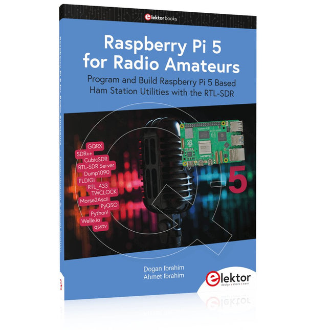
Elektor Publishing Raspberry Pi 5 for Radio Amateurs
Program and Build Raspberry Pi 5 Based Ham Station Utilities with the RTL-SDR The RTL-SDR devices (V3 and V4) have gained popularity among radio amateurs because of their very low cost and rich features. A basic system may consist of a USB based RTL-SDR device (dongle) with a suitable antenna, a Raspberry Pi 5 computer, a USB based external audio input-output adapter, and software installed on the Raspberry Pi 5 computer. With such a modest setup, it is possible to receive signals from around 24 MHz to over 1.7 GHz. This book is aimed at amateur radio enthusiasts and electronic engineering students, as well as at anyone interested in learning to use the Raspberry Pi 5 to build electronic projects. The book is suitable for both beginners through experienced readers. Some knowledge of the Python programming language is required to understand and eventually modify the projects given in the book. A block diagram, a circuit diagram, and a complete Python program listing is given for each project, alongside a comprehensive description. The following popular RTL-SDR programs are discussed in detail, aided by step-by-step installation guides for practical use on a Raspberry Pi 5: SimpleFM GQRX SDR++ CubicSDR RTL-SDR Server Dump1090 FLDIGI Quick RTL_433 aldo xcwcp GPredict TWCLOCK CQRLOG klog Morse2Ascii PyQSO Welle.io Ham Clock CHIRP xastir qsstv flrig XyGrib FreeDV Qtel (EchoLink) XDX (DX-Cluster) WSJT-X The application of the Python programming language on the latest Raspberry Pi 5 platform precludes the use of the programs in the book from working on older versions of Raspberry Pi computers.
€ 39,95
Members: € 35,96
-
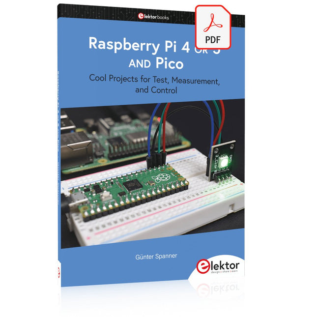
Elektor Digital Raspberry Pi 4 OR 5 AND Pico (E-book)
Cool Projects for Test, Measurement, and Control The Raspberry Pi has dominated the maker scene for many years. Freely accessible I/O pins have made it one of the most popular processor boards of all time. However, the classic Raspberry Pi has no analog inputs. Direct measurement of analog values is therefore not possible. Consequently, photodiodes, NTCs, Hall sensors, etc. cannot be read directly. In addition, the pins are connected directly to the exposed contacts, i.e. without a driver or protection circuit. This can quickly destroy the central controller and thus the entire Raspberry Pi. These problems can be elegantly solved with the Pico. As a front-end, it can easily handle a wide range of measurement tasks. In addition, the Pico is much cheaper than a classic Raspberry Pi 4 or 5. If a faulty circuit leads to the destruction of the Pico, this is relatively easy to handle. This makes the combination of a classic Raspberry Pi 4 or 5 and the Pico an ideal pair. The book introduces the broad and highly topical field of modern controller technology using the combined force of a Raspberry Pi 4 or 5 and a Raspberry Pi Pico. In addition to a detailed introduction to the operation and functionality of the controller boards themselves, the book also focuses on data acquisition and processing with digital processors. Especially the combination of both systems offers a wide range of interesting possibilities. Some practical projects from the contents: USB between Raspberry Pi 4 or 5 and Pico I²C Communication and Pico as an I²C device Voltmeter and Computer Thermometer Pico W as a Web Server and WLAN Scanner Frequency Meters and Generators OLED Displays on Raspberry Pi 4 or 5 and Pico Energy Saving Monitor Which Astronauts are in Orbit? Mini Monitor for Current Bitcoin Exchange Rate
€ 32,95
Members: € 29,66
-
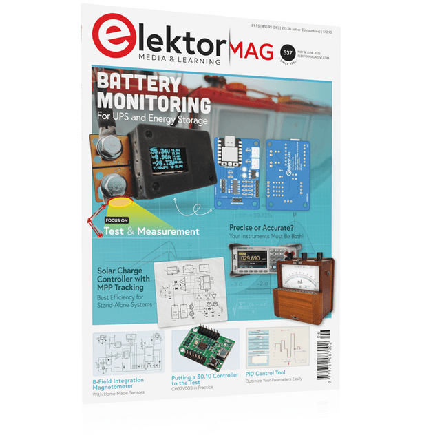
Elektor May/June 2025 (EN)
Elektor GREEN and GOLD members can download their digital edition here. Not a member yet? Click here. PbMonitor v1.0A Battery-Monitoring System for UPS and Energy Storage Applications Solar Charge Controller with MPPT (1)Basic Principles of a Solar Controller for Stand-Alone Systems B-Field Integration Magnetometer With Home-Made Sensors Precise or Accurate?Your Instruments Need to Be Both! AD7124 A Precision ADC in PracticeFeatures for Sensor Signal Conditioning PID Control ToolOptimize Your Parameters Easily embedded world 2025 Starting Out in Electronics……Continues with Tone Control Academy Pro BoxBook + Online Course + Hardware Milliohmmeter AdapterUses the Precision of Your Multimeter The Next Leap in SemiconductorsOnward Toward 1.4 nm Through-Hole Technology ConnectorsThe Best of Two Worlds: THR Frequency CounterPortable and Auto-Calibrating Via GPS Analog MetersPeculiar Parts, the Series Stand-Alone Crystal TesterHow Accurate Is Your Clock Source? Low-Cost I²C TesterConnect I²C Devices Directly to Your PC From Life’s ExperienceWho Doesn’t Honor the Small Things? 2025: An AI OdysseyThe Transformative Impact on Software Development Err-lectronicsCorrections, Updates, and Readers’ Letters Raspberry Pi Standalone MIDI Synthesizer (2)Enhancing Our Setup with Intelligence Nortonized Wien Bridge OscillatorSmall Changes Yield Significant Improvements Putting a $0.10 Controller to the TestThe CH32V003 RISC-V Microcontroller and MounRiver Studio in Practice An FPGA-Based Audio Player with Equalizer (2)Adding Volume Control, Advanced Mixing, and a Web Interface
€ 10,95
-

Elektor Publishing Multitask-Programmierung mit dem Raspberry Pi Pico
Zeitsteuerung, Scheduler, PIO und Zustandsmaschinen Multitasking ist der Schlüssel zu leistungsfähigen Embedded-Systemen, und zugleich eine der größten Herausforderungen in der Mikrocontroller-Programmierung. Dieses Buch zeigt Ihnen Schritt für Schritt, wie Sie von einem einfachen Ein-Task-Programm zu einem strukturierten, reaktionsfähigen und skalierbaren System gelangen. Dabei steht nicht nur das Wie, sondern vor allem das Warum im Mittelpunkt. Sie lernen: warum scheinbare Parallelität entsteht weshalb blockierende Programme instabil werden wie Aufgaben effizient und kontrolliert parallel ablaufen Ausgehend vom klassischen Superloop vermittelt das Buch moderne Multitasking-Strategien – von nicht-blockierender Programmierung und Tick-Systemen bis zu Task-Schedulern, Zustandsmaschinen und ereignisgesteuerten Konzepten. Der Fokus liegt auf der Praxis: Sensoren, Displays, Kommunikation und reale Anwendungen werden Schritt für Schritt integriert und mit verständlich kommentierten Beispielprogrammen erklärt. Fortgeschrittene Themen umfassen: Multicore-Programmierung mit dem Raspberry Pi Pico asynchrones Programmieren mit uasyncio RTOS-Grundlagen mit FreeRTOS die Kombination aus Multicore und RTOS Dabei werden auch die Grenzen dieser Techniken, insbesondere unter MicroPython, klar aufgezeigt. Das Buch richtet sich an ambitionierte Einsteiger und fortgeschrittene Entwickler, die Embedded-Systeme fundiert verstehen und robuste, wartbare Multitasking-Anwendungen entwickeln möchten.
€ 39,80
Best Price
-
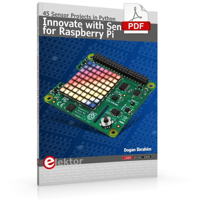
Elektor Digital Innovate with Sense HAT for Raspberry Pi (E-book)
Ready to explore the world around you? By attaching the Sense HAT to your Raspberry Pi, you can quickly and easily develop a variety of creative applications, useful experiments, and exciting games. The Sense HAT contains several helpful environmental sensors: temperature, humidity, pressure, accelerometer, magnetometer, and gyroscope. Additionally, an 8x8 LED matrix is provided with RGB LEDs, which can be used to display multi-color scrolling or fixed information, such as the sensor data. Use the small onboard joystick for games or applications that require user input. In Innovate with Sense HAT for Raspberry Pi, Dr. Dogan Ibrahim explains how to use the Sense HAT in Raspberry Pi Zero W-based projects. Using simple terms, he details how to incorporate the Sense HAT board in interesting visual and sensor-based projects. You can complete all the projects with other Raspberry Pi models without any modifications. Exploring with Sense HAT for Raspberry Pi includes projects featuring external hardware components in addition to the Sense HAT board. You will learn to connect the Sense HAT board to the Raspberry Pi using jumper wires so that some of the GPIO ports are free to be interfaced to external components, such as to buzzers, relays, LEDs, LCDs, motors, and other sensors. The book includes full program listings and detailed project descriptions. Complete circuit diagrams of the projects using external components are given where necessary. All the projects were developed using the latest version of the Python 3 programming language. You can easily download projects from the book’s web page. Let’s start exploring with Sense HAT.
€ 29,95
Members: € 26,96
-

Elektor Digital Multitask-Programmierung mit dem Raspberry Pi Pico (PDF)
Zeitsteuerung, Scheduler, PIO und Zustandsmaschinen Multitasking ist der Schlüssel zu leistungsfähigen Embedded-Systemen, und zugleich eine der größten Herausforderungen in der Mikrocontroller-Programmierung. Dieses Buch zeigt Ihnen Schritt für Schritt, wie Sie von einem einfachen Ein-Task-Programm zu einem strukturierten, reaktionsfähigen und skalierbaren System gelangen. Dabei steht nicht nur das Wie, sondern vor allem das Warum im Mittelpunkt. Sie lernen: warum scheinbare Parallelität entsteht weshalb blockierende Programme instabil werden wie Aufgaben effizient und kontrolliert parallel ablaufen Ausgehend vom klassischen Superloop vermittelt das Buch moderne Multitasking-Strategien – von nicht-blockierender Programmierung und Tick-Systemen bis zu Task-Schedulern, Zustandsmaschinen und ereignisgesteuerten Konzepten. Der Fokus liegt auf der Praxis: Sensoren, Displays, Kommunikation und reale Anwendungen werden Schritt für Schritt integriert und mit verständlich kommentierten Beispielprogrammen erklärt. Fortgeschrittene Themen umfassen: Multicore-Programmierung mit dem Raspberry Pi Pico asynchrones Programmieren mit uasyncio RTOS-Grundlagen mit FreeRTOS die Kombination aus Multicore und RTOS Dabei werden auch die Grenzen dieser Techniken, insbesondere unter MicroPython, klar aufgezeigt. Das Buch richtet sich an ambitionierte Einsteiger und fortgeschrittene Entwickler, die Embedded-Systeme fundiert verstehen und robuste, wartbare Multitasking-Anwendungen entwickeln möchten.
€ 32,80
Members: € 29,52


