
Search results for "elektor OR us OR style OR siren OR kit"
-
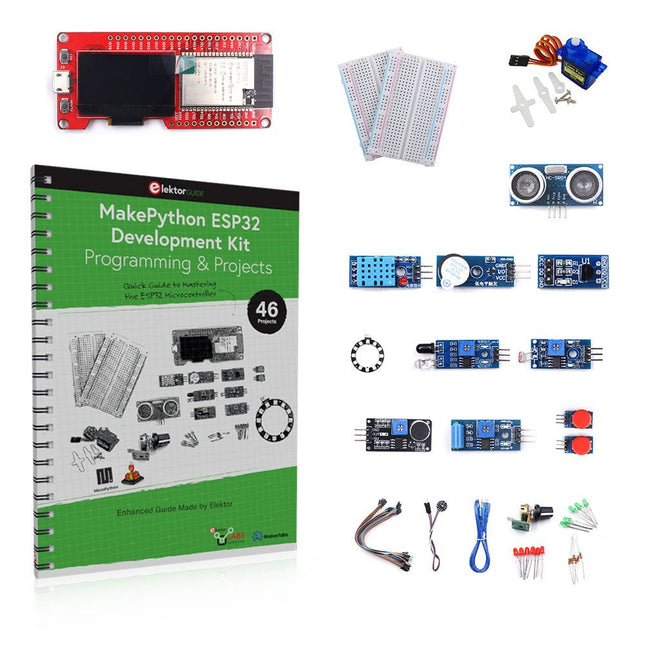
Elektor Bundles MakePython ESP32 Development Kit (EN)
Learn how to use the ESP32 Microcontroller and MicroPython programming in your future projects! The project book, written by well-known Elektor author Dogan Ibrahim, holds many software- and hardware-based projects especially developed for the MakePython ESP32 Development Kit. The kit comes with several LEDs, sensors, and actuators. The kit will help you acquire the basic knowledge to create IoT projects. The book’s fully evaluated projects feature all the supplied components. Each project includes a block diagram, a circuit diagram, a full program listing, and a complete program description. Included in the kit 1x MakePython ESP32 development board with LCD 1x Ultrasonic ranging module 1x Temperature and humidity sensor 1x Buzzer module 1x DS18B20 module 1x Infrared module 1x Potentiometer 1x WS2812 module 1x Sound sensor 1x Vibration sensor 1x Photosensitive resistance module 1x Pulse sensor 1x Servo motor 1x USB cable 2x Button 2x Breadboard 45x Jumper wire 10x Resistor 330R 10x LED (Red) 10x LED (Green) 1x Project book (206 pages) 46 Projects in the Book LED Projects Blinking LED Flashing SOS Blinking LED – using a timer Alternately flashing LEDs Button control Changing the LED flashing rate using pushbutton interrupts Chasing-LEDs Binary-counting LEDs Christmas lights (random-flashing 8 LEDs) Electronic dice Lucky day of the week Pulsewidth Modulation (PWM) Projects Generate a 1000-Hz PWM waveform with 50% duty cycle LED brightness control Measuring the frequency and duty cycle of a PWM waveform Melody maker Simple electronic organ Servo motor control Servo motor DS18B20 thermometer Analog To Digital Converter (ADC) Projects Voltmeter Plotting the analog input voltage ESP32 internal temperature sensor Ohmmeter Photosensitive resistance module Digital To Analog Converter (DAC) Projects Generating fixed voltages Generating a sawtooth-wave signal Generating a triangular-wave signal Arbitrary periodic waveform Generating a sinewave signal Generating accurate sinewave signal using timer interrupts Using The OLED Display Seconds counter Event counter DS18B20 OLED based digital thermometer ON-OFF temperature controller Measuring the temperature and humidity Ultrasonic distance measurement Height of a person (stadiometer) Heart rate (pulse) measurement Other Sensors Supplied with the Kit Theft alarm Sound-activated light Infrared obstacle avoidance with buzzer WS2812 RGB LED ring Timestamping temperature and humidity readings Network Programming Wi-Fi scanner Remote control from the Internet browser (using a smartphone or PC) – Web Server Storing temperature and humidity data in the Cloud Low-Power Operation Using a timer to wake up the processor
€ 89,95€ 69,95Best Price
-
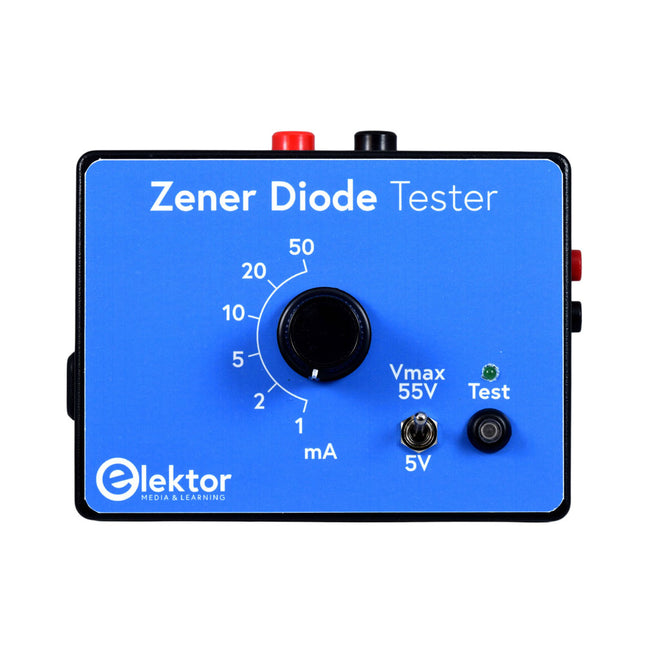
Elektor Zener Diode Tester
The Elektor Zener Diode Tester is essentially a constant-current source that can be switched in steps from 1 to 50 mA. It can be used to test Z-diodes up to a maximum of 54 V. Thanks to a 60-V step-up converter, the device can be powered by the usual 5 to 12 V. The principle of this tester is straightforward. A Z-diode or other DUT (device under test, such as an LED) is biased by an adjustable current source. The voltage across the DUT can be measured with a multimeter. The voltage of most (small) Z-diodes is specified at a current of 5 mA. Depending on the application, the voltage at other currents can also be of interest. That is why six current settings are available: 1, 2, 5, 10, 20, and 50 mA. LEDs are often specified at a current of 20 mA. What can be tested is: Whether a Z-diode is defective (short circuit or high impedance). Whether a Z-diode exhibits the correct Z-voltage. How a Z-voltage changes with different currents. What exact voltage is present at an integrated voltage reference. Whether LEDs in a series chain differ in brightness (hence the 20 mA current). What the current gain is for different base currents in (power) transistors. The kit contains all parts listed in the bill of materials including PCB and enclosure. Specifications Supply voltage 5…12 V/2 A (USB-C) Supply current (Itest = 50 mA) 1.1 A @ 5 V / 412 mA @ 12 V Selectable currents 1, 2, 5, 10, 20, and 50 mA Max. test voltage >54 V @ Itest ≥1 mA Max. output voltage 60 V @ Itest = 0 mA Voltage limit at 5 V 4.5 V @ Itest = 1 mA / 5.18 V @ Itest = 50 mA Enclosure dimensions 110 x 82 x 44 mm PCB size 105.4 x 67.3 mm Connections 4 mm banana sockets for multimeter 2 mm banana sockets for test clips USB-C socket for power supply Included Resistors R1 = 3.3 kΩ, 600 mW, 1% R2 = 0.15 Ω, 1 W, 5%, LS 12.7 mm, ø 3.5 mm R3, R8 = 180 Ω, 600 mW, 1% R4, R6, R16 = 1 kΩ, 600 mW, 1% R5, R19 = 47 kΩ, 600 mW, 1% R7 = 3.9 kΩ, 1 W, 5%, LS 12.7 mm, ø 3.5 mm R9, R10, R12 = 10 kΩ, 600 mW, 1% R11, R13 = 100 Ω, 600 mW 1% R14 = 249 Ω, 600 mW, 1% R15 = 499 Ω, 600 mW, 1% R17 = 2.49 kΩ, 250 mW, 1% R18 = 4.99 kΩ, 250 mW, 1% Capacitors C1 = 470 uF / 35 V, 20%, Ir = 1.86 A, ø 12.5 mm, LS 5 mm, ESR = 0.038 Ω (Panasonic EEUTP1V471) C2 = 1 uF / 100 V, 10%, X7R, LS 5 mm C3 = 2.2 nF / 50 V, 10%, X7R, LS 5 mm C4, C7 = 100 nF / 100 V, 10%, X7R, LS 5 mm C5 = 100 uF / 100 V, 20%, ø 14 mm max., LS 5 mm C6 = 1 nF / 100 V, 10%, X7R, LS 5 mm Inductor L1 = 100 uH, Irms = 2.4 A, Isat = 3.5 A, 0.09 Ω, radial, pitch 2.5/5/10 mm, ø 14 mm max. (Kemet SBC8-101-242) Semiconductors D1 = MUR120G, DO-41 D2, D4 = STPS3150RL, DO-201AD D3 = Z-diode, 18 V, 1.3 W (BZX85C18) D5 = Z-diode, 5.1 V, 0.5 W (1N5231B) LED1 = LED in pushbutton S1 LED2 = LED, green, 3 mm IC1 = MC34063, DIP-8 IC2 = LM4040BIZ-5.0/NOPB, TO-92 (TO-226AA-3) IC3 = TL051CP, DIP-8 T1 = BC327.25, TO-92 T2 = STP40NF10L, TO-220 T3 = IRF9510PBF, TO-220 T4 = 2N7000, TO-92 Others K1, K2, S1, S3 = 2-way screw terminal block, LS 3.5 mm, max. 1.5 mm² connected to K1 = USB-C socket, 30 V/3 A, chassis mounted, wired, 9 x 16 mm connected to K2 = Banana Connector, 2 mm, Socket, 60 VDC, Panel Mount, red (Multicomp 24.102.1) connected to K2 = Banana Connector, 2 mm, Socket, 60 VDC, Panel Mount, black (Multicomp 24.102.2) Test clip, red, 30 VAC/60 VDC (Hirschmann 931467101) Test clip, black, 30 VAC/60 VDC (Hirschmann 931467100) S1 = Pushbutton, panel mount, SPST-NO, 30 DC/100 mA, with red LED S2 = Rotary Switch, 6 position, 2 pole, 30°, 250 V/150 mA S3 = Toggle switch, panel mount, SPDT, solder lugs, 28 VDC T2, T3 = Heat sink, 15°C/W, FK 214 SA-CB Enclosure Hammond 1591XXSSBK, ABS, 110 x 82 x 44 mm Knob for S2, round shaft 6 mm, ø 21 mm, with indicator line (Multicomp CP-LB21-6-6D) 4 x Self-tapping screw #4-1/4", carbon steel, pan head Banana plug, red, 2 mm, 60 VDC (Multicomp 25.205.1) Banana plug, black, 2 mm, 60 VDC (Multicomp 25.205.2) Banana socket, black 4 mm, panel mount Banana socket, red 4 mm, panel mount for LED1, LED2 = Pin header, 1 x 2, vertical, pitch 2.54 mm for LED1, LED2 = Pin socket, 1 x 2, vertical, pitch 2.54 mm for T2, T3 = M3 screw, 10 mm, steel, pan head 2 x M3 washer, plain, steel 4 x M3 nut for IC1, IC3 = DIP-8 socket Wire, black, 0.25 mm² (24 AWG), stranded 14 x 0.15 mm, 1 m Wire, red, 0.25 mm² (24 AWG), stranded 14 x 0.15 mm, 1 m PCB 250772-1 v1.1 Links Article Elektor Labs
€ 79,95
Best Price
-

Elektor Labs Elektor Low-Noise Lab Power Supply
The Elektor Low-Noise Lab Power Supply is a fully analogue, adjustable, medium-power symmetrical bench supply that contains no switching or digital components. It provides an output voltage adjustable between 0 V and ±22 V, and an output current adjustable from 0 A to 1 A. Because it avoids any form of switching circuitry, the design delivers extremely low noise. To display both output voltages and currents, four miniature moving-coil panel meters are used. Most modern laboratory power supplies and AC adapters employ switch-mode techniques. Even the best examples inevitably exhibit high-frequency ripple and other switching artefacts on their output, which can interfere with the testing of sensitive analogue circuits and disturb low-level measurements. To overcome this, the concept here is a completely analogue power supply. Although less efficient than its switch-mode counterparts, the reduced efficiency is of little importance for test-bench use and ensures cleaner, more reliable measurement results. Because many analogue circuits require a symmetrical supply, this design delivers positive and negative output voltages of equal magnitude. A small amount of adjustment is available to compensate for any imbalance. Naturally, a variable current-limit function is also included. The kit includes the components required to build the power supply, except for the transformers. Specifications Output Voltage 0…+22 V, 0, −22 V Output Current 0…+1 A, 0…−1 A Noise −85 dBV, (at 0.95 A/20 V, B = 22 kHz) −84 dBV (at 0.95 A/20 V, B > 500 kHz) Ripple 50 µVRMS (at 950 mA/20 V, B = 22 kHz, mainly 100 Hz component) Included 3x PCBs: Regulator (PCB-1), Mains Filter (PCB-2) and Transformer (PCB-3) All the components except the AC transformers 4x moving-coil meters Additional parts for wiring (wires, banana sockets, IEC Power entry module, etc.) Not included The three AC transformers An enclosure Parts List For the Regulator PCB (240386-1) Resistors (250 mW, 1%) R1 = 12 Ω R2, R8, R37, R62 = 1 MΩ R3, R7, R10, R13, R17, R20, R22, R30, R35, R42, R45, R47, R55, R60 = 100 Ω, 600 mW R4, R5 = 4.7 kΩ R6 = 100 kΩ R9, R12, R14, R36, R38, R39, R61, R63, R66, R72, R78, R79 = 10.0 kΩ, 600 mW R11 = 9.76 kΩ, 600 mW R15, R40 = 44.2 kΩ, 600 mW R16, R41, R77 = 1 kΩ R18, R43 = 1.5 kΩ, 1 W, 5% R19, R44 = 470 Ω, 1 W, 5% R21, R46 = 330 Ω, 600 mW R23, R24, R48, R49 = 1.0 Ω, 1 W R25, R50 = 1 kΩ, 1 W, 5% R26, R28, R51, R53 = 1.000 kΩ 0.1%, 15 ppm/C R27, R29, R52, R54 = 10.00 kΩ 0.1%, 15 ppm/C R31, R56 = 1.2 kΩ, 1 W, 5% R32, R57 = 47 kΩ R33, R58 = 270 Ω R34, R59 = 27 kΩ R64, R69 = 12.0 kΩ R65 = 3.0 kΩ, 600 mW R67, R80 = 470 Ω, 600 mW R68, R70 = 6.8 kΩ, 600 mW R71 = 30.0 kΩ,, 600 mW R73, R74, R75, R76 = 10 MΩ P1, P2, P3 = 10 kΩ, 200 mW, 20%, potentiometer, 1 turns, single, lin., panel mount P4, P5 = 500 Ω, 500 mW, 10%, trimmer, 25 turns, 3296Y-1-501LF Bourns P6, P7 = 10 kΩ, 500 mW, 10%, trimmer, 25 turns, 3296Y-1-501LF Bourns Capacitors C1 = 100 nF, 50 V, 10%, ceramic X7R, LS 5 mm C2, C3, C6, C7, C30 = 10 µF, 63V, 20%, LS 2.5 mm, 3000hours@105°C C4, C5, C8, C9, C13, C14, C18, C19, C23, C24, C28, C29, C31, C32, C38, C39 = 100 nF, 250 V, 10%, PET, LS 7.5 mm C10, C20 = 47 nF, 100 V, 5%, PET, LS 5 mm C11, C21 = 10 nF, 100 V, 5%, PET, LS 5 mm C12, C22 = 220 µF, 35 V, 20%, 0.024 Ω, LS2.5/3.5 mm, Ir 3.4 A, 2000hours@125°C, polymer C15, C25 = 120 µF, 50 V, 20%, ESR 0.02 Ω, Diam. 10 mm max., LS 5 mm C16, C26 = 15 nF, 100 V, 5%, PET, LS 5 mm C17, C27 = 47 nF, 100 V, 5%, PET, LS 5 mm C33, C34 = 22 µF, 50 V, 20%, LS 2 mm, 10000 hours @ 105°C C35, C36, C44, C45 = 1 µF, 100 V, 10%, LS 5 mm, ceramic X7R C37 = 100 uF, 50 V, 20%. LS 3.5 mm C40, C41, C42, C43, C46, C47, C48, C49 = 1000 µF, 50 V, 20%, LS 5/7.5 mm, Ir 3.32 A, 10000hours@105°C, D 16 mm C50, C51, C52, C53 = 47 nF, 100 V, 10%, ceramic X7R, LS 5 mm Inductors L1, L2 = 4.7 µH, 3.2 A, 0.033 Ω, LS 5 mm, RLB0914-4R7ML Bourns L3 = Commom mode choke, 14.5 mH, 3 A, SSRH24NH-30145 Kemet Semiconductors D1, D2, D3, D4, D5, D9, D10, D11, D15 = BAT85, DO-34 D6, D7, D12, D13 = SR560, DO-201AD D8, D14, D16 = 1N4148, DO-35 D17 = Zenerdiode, 5.6 V, 0.5 W, DO-41 D18, D19 = 1N4004, DO-41 D20, D21 D22, D23 = V30100CI-M3/P, dual common cathode, TO-220 D24 = Zener diode, 30 V, 1 W, DO-41 LED1, LED2 = LED, red, T-1 (3 mm) LED3, LED4 = LED, green, T-1 (3 mm) TVS1, TVS2 = BZW50-33B, R6 T1, T2, T4 = BC337.25, TO-92 T3 = NJW0302G, TO-3P T5, T6, T8 = BC327.25, TO-92 T7 = NJW0281G, TO-3P T9 = BD139, TO-126 (SOT-32) IC1 = LM334Z, TO-92 IC2 = LM4040AIZ-5.0/NOPB, TO-92 (TO-226AA-3) IC3, IC4 = OPA2992IDR, SOIC-8 IC5, IC6 = OPA4992IDR, SOIC-14 IC7 = OPA992IDBVR, SOT-23-5 IC8 = LM339N, DIP-14 IC9 = LM317, TO-220 IC10 = LM337, TO-220 Others F1, F2 = 5×20 mm fuse, 1.6 A, fast acting HS1, HS2 = Heatsink MC33271 (for T3/T7), 2.7°C/W, PCB mount, height 63.5 mm K1, K4 = 3-way screw terminal block, LS 3.5 mm, max. 1.5 mm² K2, K3 = 3-way screw terminal block, LS 3.5 mm, max. 1 mm² M1, M3 = Moving coil meter, Range 30 V, type 91C4, 45×45 mm M2, M4 = Moving coil meter, Range 1 A, type 91C4, 45×45 mm² RE1 = Relay DPDT,5V, UA2-5NU Miscellaneous 3× 3-way screw terminal block, LS 3.5 mm, max. 1 mm² (for P1, P2, P3) 4× Pin header, 1×2, vertical, pitch 2.54 mm (for LED1, LED2, LED3, LED4) 4× Pin socket, 1×2, vertical. pitch 2.54 mm (for LED1, LED2, LED3, LED4) 2× Heatsink FK222SA220, 20°C/W, PCB mount (for IC9 & IC10) 2× Mica thermal pad for TO-220, 12×18×0.05 mm (for IC9 & IC10) 2× Insulating bushing IB 6, TO-220 (for IC9 & IC10) 2× Ceramic thermal pad, 23×20×2 mm (for T3 & T7) 2× PCB Fuse Holder, for 5×20 mm fuse, 10 A (for F1, F2) 2× Cover for PCB Fuse Holder, transparent (for F1, F2) 2× 2-way screw terminal block, LS 3.5 mm, max. 1 mm² (for M1 & M3) 2× 2-way screw terminal block, LS 3.5 mm, max. 1.5 mm² (for M2 & M4) 8× M3 solder lug, thickness 0.35 mm (for M1…M4) M4 solder lug, thickness 0.35 mm (to connect 4 mm banana connectors) Screened cable, 1 pair, 2×24 AWG/0.22 mm², 1 m (for P1, P2 & P3) IC socket, DIP, 14 contacts (for IC8) M3 washer, plain, steel M3 screw, 16 mm, steel, pan head M3 nut M3 spring washer 50 mm M3 standoff, steel, male-female 12 mm M3 standoff, steel, male-female 10 mm M3 standoff, steel, male-female M3 screw, 8 mm, steel, pan head For the Mains Fiter PCB (240386-2) Resistor R1 = 220 kΩ, 1 W, 500 V, 5% Capacitors C1, C2 = 470 nF, 305 VAC, Class X2, 11 × 27 mm max., LS 15/22.5 mm C3, C4, C5, C6 = 2.2 nF, 300 VAC, Class Y2, 13 × 4 mm, LS 10 mm, PP Inductors L1, L2 = Common-mode choke, 6.8 mH, 1.7 A, TDK B82732R2172B030 Semiconductor MOV1 = TVS varistor, 300 VAC, S14K300 (230 VAC, B72214S0301K101) and SK14K150 (150 VAC, B72214S0151K101) Others K1, K2 = 3-way screw terminal block, LS 7.62 mm F1 = Time-delay fuse, 0.5 A (230 VAC) or 1 A (115 VAC) Miscellaneous 1× Fuse holder, 5×20 mm, 10 A, 500 VAC 1× Transparent fuse cover 4× 10 mm M3 standoff, steel, male–female 4× M3 screw, 8 mm, steel, pan head 4× M3 nut For the Transformer PCB (240386-3) Resistors R1, R2 = 2.7 kΩ, 600 mW, 1% R3 = 10.0 kΩ, 600 mW, 1% Capacitor C1 = 220 µF, 50 V, 20%, Ø10 mm, LS 5 mm, 4000 h @ 105°C Transformers (not included in this kit!) TR1, TR2, TR3 = 2×7 V, 25 VA, PCB-mounted toroid, 70060K Talema Semiconductors D1–D4 = 1N4148, DO-35 D5, D6 = 1N4004, DO-41 D7 = Zener 5.6 V, 1.3 W, DO-41 LED1 = LED, red, T-1 (3 mm) IC1, IC2 = MOC8021M, CTR ≥ 1000%, DIP-6 Others F1, F2, F3 = 160 mA time-delay fuse (230 VAC) or 315 mA time-delay fuse (115 VAC) K1 = 2-way screw terminal block, LS 7.62 mm K2 = 3-way screw terminal block, LS 3.5 mm, max 1.5 mm² K3, K4 = 3-way screw terminal block, LS 3.5 mm, max 1 mm² RE1, RE2 = Relay DPDT, 5 A/250 VAC / 24 VDC Miscellaneaous 1× Pin header 1×2, pitch 2.54 mm + matching socket for LED1 3× Fuse holder 5 × 20 mm, 10 A, 500 VAC + transparent cover 3× M4 screw, 8 mm, pan head + washer for TR1-TR3 8× M3 screw, 8 mm, pan head + nut + washer 8× 10 mm M3 standoff, steel, male–female 2× IC socket, DIP-6 for IC1 & IC2 Additional Parts 1 m red insulated wire, stranded, 1.5 mm² 0.5 m blue insulated wire, stranded, 1.5 mm² 0.5 m black insulated wire, stranded, 1.5 mm², 0.5 m 2 m red insulated wire, stranded, D 0.56 mm (0.25 mm²) 2 m black insulated wire, stranded, D 0.56 mm (0.25 mm²) 0.5 m Multicore Cable, Flexible, 3 Core, 0.75 mm² (24 x 0.2 mm) Red banana socket Black banana socket Blue banana socket Green banana socket IEC Power Entry Module with switch, IEC C14 3 crimp terminals, FASTON, 4.75 x 0.81 mm 3 knobs Links Elektor Labs JumpStarter Page Article (Part 1) Article (Part 2)
€ 249,00
Best Price
-

Elektor Bundles 555-Timer-Projekte (Bundle)
Dieses Bundle befasst sich mit der Entwicklung von Projekten, die auf dem 555-Timer-IC basieren. Das Buch enthält über 45 vollständig getestete und dokumentierte Projekte. Zusammen mit dem Kit, das mehr als 130 durchkontaktierte Bauteile enthält, können Sie alle beschriebenen Projekte auf einem Breadboard nachbauen. Der Aufbau macht es auch einfach, die Projekte zu modifizieren und mit ihnen zu experimentieren. Über 45 Projekte für den legendären 555-Chip (und den 556, 568) Einige der Projekte im Buch sind: Abwechselnd blinkende LEDs Veränderung der Blinkrate von LEDs Touchsensor-Ein/Aus-Schalter Ein-/Ausschaltverzögerung Lichtabhängiger Ton Dunkel-Hell-Lichtschalter Tonburst-Generator Langzeit-Timer Lauflichter LED-Roulette-Spiel Ampelsteuerung Durchgangsprüfer Elektronisches Schloss Kontaktentprellung für Schalter Spielzeug-Elektronikorgel Mehrfachsensor-Alarmsystem Metronom Spannungsmultiplizierer Elektronischer Würfel 7-Segment-Display-Zähler Motorsteuerung 7-Segment-Display-Würfel Elektronische Sirene Verschiedene andere Projekte Inhalt des Kits Widerstände 1x 15 kΩ 1x 68 kΩ 2x 47 kΩ 1x 82 kΩ 2x 820 Ω 1x 8,2 kΩ 3x 10 kΩ 1x 1,8 kΩ 1x 6,8 kΩ 14x 2,2 kΩ 10x 680 Ω 1x 27 kΩ 1x 5,6 kΩ 1x 560 kΩ 1x 4,7 kΩ 1x 3,3 kΩ 3x 33 kΩ 1x 36 kΩ 2x 100 kΩ 5x 1 kΩ 1x 3,9 kΩ 2x 56 kΩ 2x 12 kΩ 1x 10 kΩ Potentiometer 1x 1 MΩ Potentiometer 2x 50 kΩ Potentiometer 3x 20 kΩ Potentiometer 1x 10 kΩ Potentiometer 1x 10 kΩ Potentiometer 1x 50 kΩ Potentiometer 1x 100 kΩ Potentiometer 1x 50 kΩ Potentiometer Kondensatoren 1x 0,33 μF 1x 1 μF 1x 10 nF 1x 22 nF 1x 47 nF 1x 100 nF 1x 10 μF electrolytisch 1x 33 μF electrolytisch 2x 100 μF electrolytisch LEDs 10x 5 mm rote LED 10x 3 mm rote LED 3x 3 mm gelbe LED 3x 3 mm grüne LED 1x 7-Segment-LED mit gemeinsamer Kathode Halbleiter 3x 555-Timer 1x CD4017 Counter 1x CD4026 Counter 1x CD4011 NAND-Gate 4x 1N4148 Diode 1x IRFZ46N MOSFET 1x Thermistor 1x Lichtabhängiger Widerstand (LDR) Sonstiges 1x Passiver Summer 1x Aktiver Summer 1x SG90-Servo 1x 8 Ω Mini-Lautsprecher 1x 9 V DC Bürstenmotor 1x 5 V Relais 1x 9 V Batterieclip 7x Drucktastenschalter 1x Breadboard 1x Breadboard-Überbrückungskabel
€ 69,95€ 54,95Best Price
-
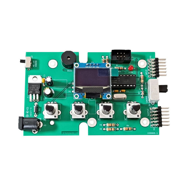
Elektor Labs Elektor Super Servo Tester Kit
The Elektor Super Servo Tester can control servos and measure servo signals. It can test up to four servo channels at the same time. The Super Servo Tester comes as a kit. All the parts required to assemble the Super Servo Tester are included in the kit. Assembling the kit requires basic soldering skills. The microcontroller is already programmed. The Super Servo Tester features two operating modes: Control/Manual and Measure/Inputs. In Control/Manual mode the Super Servo Tester generates control signals on its outputs for up to four servos or for the flight controller or ESC. The signals are controlled by the four potentiometers. In Measure/Inputs the Super Servo Tester measures the servo signals connected to its inputs. These signals may come from for instance an ESC, a flight controller, or the receiver or another device. The signals are also routed to the outputs to control the servos or the flight controller or ESC. The results are shown on the display. Specifications Operating modes Control/Manual & Measure/Inputs Channels 3 Servo signal inputs 4 Servo signal outputs 4 Alarm Buzzer & LED Display 0.96' OLED (128 x 32 pixels) Input voltage on K5 7-12 VDC Input voltage on K1 5-7.5 VDC Input current 30 mA (9 VDC on K5, nothing connected to K1 and K2) Dimensions 113 x 66 x 25 mm Weight 60 g Included Resistors (0.25 W) R1, R3 1 kΩ, 5% R2, R4, R5, R6, R7, R9, R10 10 kΩ, 5% R8 22 Ω, 5% P1, P2, P3, P4 10 kΩ, lin/B, vertical potentiometer Capacitors C1 100 µF 16 V C2 10 µF 25 V C3, C4, C7 100 nF C5, C6 22 pF Semiconductors D1 1N5817 D2 LM385Z-2.5 D3 BZX79-C5V1 IC1 7805 IC2 ATmega328P-PU, programmed LED1 LED, 3 mm, red T1 2N7000 Miscellaneous BUZ1 Piezo buzzer with oscillator K1, K2 2-row, 12-way pinheader, 90° K5 Barrel jack K4 1-row, 4-way pin socket K3 2-row, 6-way boxed pinheader S1 Slide switch DPDT S2 Slide switch SPDT X1 Crystal, 16 MHz 28-way DIP socket for IC2 Elektor PCB OLED display, 0.96', 128 x 32 pixels, 4-pin I²C interface Links Elektor Magazine Elektor Labs
€ 59,95
Members: € 53,96
-

Elektor Bundles Physical AI with Raspberry Pi (Bundle)
This bundle contains the AI Fusion Lab Kit – which includes over 450 components – and the book Physical AI with Raspberry Pi, offering a comprehensive, hands-on introduction to AI, electronics, and Python programming. Build practical projects that combine computer vision, voice interaction, sensors, motors, and large language models. The included book guides you step by step from Raspberry Pi setup and hardware control to advanced applications using OpenCV, MediaPipe, YOLO, OpenAI services, and local Ollama models. SunFounder AI Fusion Lab Kit for Raspberry Pi (450+ parts) The AI Fusion Lab Kit transforms a Raspberry Pi into a complete platform for learning artificial intelligence, electronics, and Python programming. It supports Raspberry Pi 5, 4B, 3B+, 3B, and Zero 2 W, as well as popular AI models and services including ChatGPT, Gemini, Grok, DeepSeek, Qwen, Doubao, and Ollama. With its camera, Pan-Tilt HAT, 10-axis sensor module, microphone, speaker, and electronic components, the kit enables users to build interactive AI projects that combine voice, vision, movement, and sensor data. It is suitable for beginners, students, makers, and anyone who wants to explore practical AI applications. Build Multimodal AI Projects Combine large language models with speech recognition, text-to-speech, camera vision, sensors, and breadboard circuits. Create projects that can listen, speak, see, react, and interact with their environment while learning how modern AI systems work. Explore AI Vision and Object Tracking Use YOLO, OpenCV, and MediaPipe to detect and track objects, colors, faces, and human movement. The motorized Pan-Tilt HAT allows the camera to follow targets automatically, demonstrating how computer vision and motion control work together. Voice AI with the Fusion HAT+ The Fusion HAT+ simplifies hardware control through a unified Python library and supports safe Raspberry Pi shutdown. Its integrated microphone and speaker make it easy to develop voice-controlled assistants and other conversational AI applications. Compatible with Raspberry Pi 5, 4B, 3B+, 3B, and Zero 2 W Supports multiple cloud-based and local AI models Includes camera, Pan-Tilt HAT, 10DOF module, microphone, and speaker Projects covering voice AI, computer vision, sensors, and electronics Video lessons, documentation, and sample code Book: Physical AI with Raspberry Pi Using the Raspberry Pi and the AI Fusion Lab Kit, this book takes you step by step from the fundamentals of hardware interfacing to the development of intelligent systems capable of seeing, listening, speaking, and making decisions. Whether you are a student, educator, maker, or professional engineer, you will gain valuable experience through projects designed to build both knowledge and confidence. Beginning with system setup, GPIO programming, sensors, displays, motors, and automation techniques, the book gradually introduces more advanced topics, including speech recognition, text-to-speech synthesis, conversational AI, object recognition, and machine learning. Along the way, you will learn how to create voice-controlled devices, intelligent assistants, camera tracking systems, environmental monitoring solutions, and AI-powered embedded applications. Explore modern technologies such as OpenAI services, Ollama local large language models, OpenCV, MediaPipe, and YOLO object detection while gaining practical experience with real-world applications used in robotics, industrial automation, smart devices, and autonomous systems. You’ll discover how intelligent software can interact with sensors, cameras, motors, and displays to create systems that respond naturally to the world around them. Rather than simply following code examples, you will be encouraged to experiment, customize, and expand every project. The techniques and skills developed throughout this book provide a solid foundation for future innovation, rapid prototyping, research, and product development. If you are ready to move beyond traditional electronics and explore the future of intelligent embedded systems, this book will guide you every step of the way. This bundle contains: SunFounder AI Fusion Lab Kit for Raspberry Pi (normal price: €100) Book: Physical AI with Raspberry Pi (normal price: €45) Not included Raspberry Pi
€ 129,95
Best Price
-
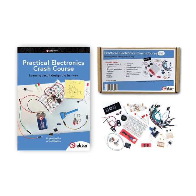
Elektor Bundles Practical Electronics Crash Course (Bundle)
Getting started in electronics is not as difficult as you may think. With this bundle (book + kit of parts), you can explore and learn the most important electrical and electronics engineering concepts in a fun way by doing various experiments. You will learn electronics practically without getting into complex technical jargon and long calculations. As a result, you will be creating your own projects soon. This kit contains the components required to build most of the detailed examples of the book on a breadboard and try them out for real. The kit can, of course, also be used without the book for building other circuits and doing your own experiments. Kit contents 1x 39 Ω, 1 W resistor 1x 47 Ω resistor 1x 180 Ω resistor 1x 330 Ω resistor 3x 1 kΩ resistor 1x 2.2 kΩ resistor 1x 3.9 kΩ resistor 1x 6.8 kΩ resistor 1x 10 kΩ resistor 1x 15 kΩ resistor 1x 22 kΩ resistor 1x 33 kΩ resistor 1x 47 kΩ resistor 1x 56 kΩ resistor 1x 82 kΩ resistor 1x 120 kΩ resistor 1x 680 kΩ resistor 2x 100 kΩ resistor 1x 10 kΩ trimmer 1x 10 kΩ linear potentiometer 1x 100 kΩ linear potentiometer 1x LDR 1x 1 nF ceramic capacitor 2x 10 nF ceramic capacitor 1x 100 nF ceramic capacitor 1x 1 µF, 25 V aluminium electrolytic capacitor 2x 10 µF, 25 V aluminium electrolytic capacitor 1x 100 µF, 25 V aluminium electrolytic capacitor 1x 470 µF, 25 V aluminium electrolytic capacitor 1x 1000 µF, 25 V aluminium electrolytic capacitor 1x RGB LED, Common-Cathode (CC) 1x 1N4148 small signal diode 1x 1N4733A 5.1 V, 1 W Zener diode 3x LED, red 2x BC337 NPN transistor 1x IRFZ44N N-channel MOSFET 2x NE555 timer 1x LM393 comparator 1x 74HCT08 quad AND gate 3x Tactile switch 2x SPDT switch 1x Relay, SPDT, 9 VDC 1x Active buzzer 1x Passive buzzer 50 cm Solid wire, 16 AWG, unjacketed 2x PP3 9 V battery clip 1x Breadboard 20x Jumper wire This bundle contains: Practical Electronics Crash Course Kit (valued at: €45) Book: Practical Electronics Crash Course (normal price: €45)
€ 89,95€ 69,95Best Price
-
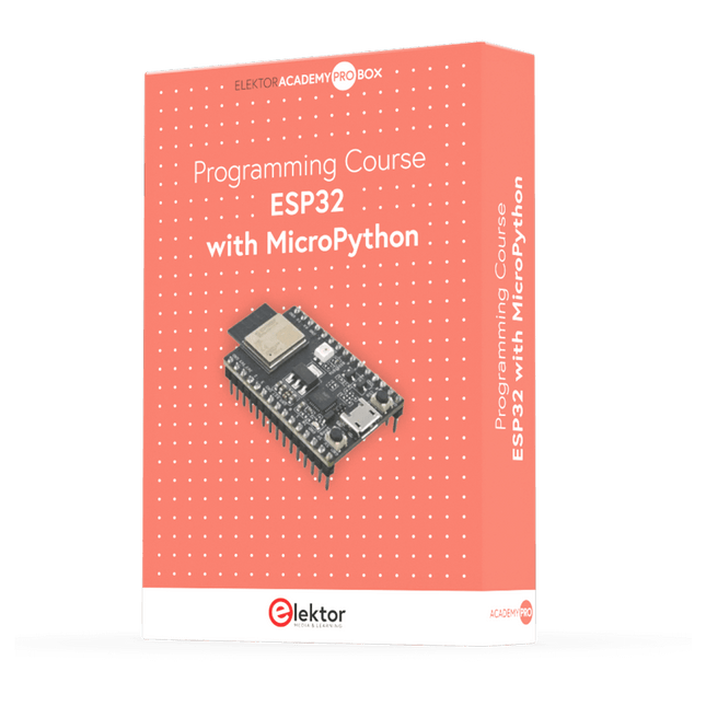
Elektor Academy Pro ESP32 with MicroPython (Programming Course)
This complete ESP32 microcontroller programming course features a textbook, a component kit, hands-on projects, and a comprehensive online course with simulations. It is ideal for step-by-step learning of embedded systems programming in MicroPython using a practical, hands-on approach. A Practical Introduction to Embedded Systems with the ESP32 This course is designed for people who are new to embedded systems and looking for a structured, example-driven way to get started. A kit of parts comprising LEDs and resistors, switches, sensors and actuators, displays, a breadboard and wires, and more is included. These are used in the course to illustrate example applications. No prior experience with Arduino or embedded development is required. Each section features hands-on examples and mini projects designed to reinforce key concepts and inspire deeper exploration. By the end of the course, you’ll be able not only to reproduce the examples but also to build on them with your own ideas and applications. What Will You Learn? Microcontroller programming in MicroPython with the ESP32 using the Thonny IDE Working with Digital I/O, read buttons and encoders, control LEDs and relays Read analog inputs, voltages, and analog sensors Generating analog output signals and PWM Use serial communication like UART, I²C and SPI to control displays and read digital sensors and SD cards Managing time Working with interrupts Real-time sensor input and control via buttons, LEDs, and displays Control actuators like relays and servo motors Who Is It For? Students and self-learners exploring embedded systems Makers and IoT enthusiasts looking to improve their hardware skills Educators and trainers seeking ready-to-teach material What's Inside the Box? Access to the full course on the Elektor Academy Pro Learning Platform ESP32 microcontroller board + USB cable Book: Programming Microcontrollers in MicroPython Downloadable project files for every module Component Box: 2× LED, red, 5 mm LED, green, 5 mm 3× Resistor, 470 Ω, 0.25 W LDR Potentiometer, 10 kΩ, linear Pushbutton Rotary encoder module Relay module DHT22 Humidity & Temperature Sensor TM1637-compatible 4-digit 7-segment display MPU-6050 IMU with headers SSD1306-compatible I²C OLED display Micro SD card adapter with header Buzzer SG90 Micro Servo ILI9341-compatible SPI 240×320 TFT display 20× Jumper wires Breadboard All Programming Courses (and differences in content) Course Arduino Raspberry Pi Pico with Arduino C/C++ ESP32 with Arduino C/C++ Raspberry Pi Pico with MicroPython ESP32 with MicroPython Online Course Access to Arduino Course Access to Pico with Arduino C/C++ Course Access to ESP32 with Arduino C/C++ Course Access to Pico with MicroPython Course Access to ESP32 with MicroPython Course Board Uno R3 Raspberry Pi Pico ESP32 Raspberry Pi Pico ESP32 Book Programming Microcontrollers in C/C++ Using Arduino Programming Microcontrollers in C/C++ Using Arduino Programming Microcontrollers in C/C++ Using Arduino Programming Microcontrollers in MicroPython Programming Microcontrollers in MicroPython Kit 40-piece Component Box 40-piece Component Box 40-piece Component Box 40-piece Component Box 40-piece Component Box
€ 69,95
Members: € 62,96
-
Elektor Labs Elektor Sand Clock for Raspberry Pi Pico
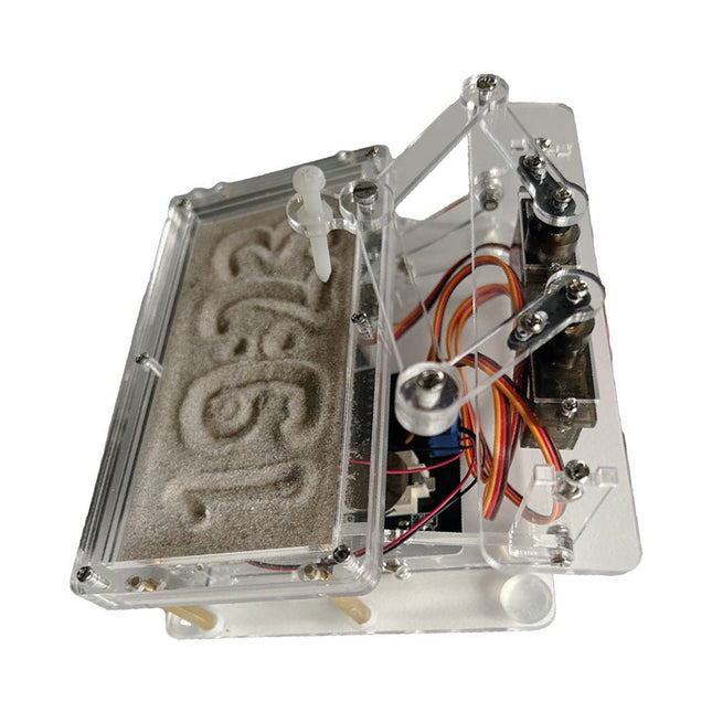
Raspberry Pi-based Eye Catcher A standard sand clock just shows how time passes. In contrast, this Raspberry Pi Pico-controlled sand clock shows the exact time by “engraving” the four digits for hour and minute into the layer of sand. After an adjustable time the sand is flattened out by two vibration motors and everything begins all over again. At the heart of the sand clock are two servo motors driving a writing pen through a pantograph mechanism. A third servo motor lifts the pen up and down. The sand container is equipped with two vibration motors to flatten the sand. The electronic part of the sand clock consists of a Raspberry Pi Pico and an RTC/driver board with a real-time clock, plus driver circuits for the servo motors. A detailed construction manual is available for downloading. Features Dimensions: 135 x 110 x 80 mm Build time: approx. 1.5 to 2 hours Included 3x Precut acrylic sheets with all mechanical parts 3x Mini servo motors 2x Vibration motors 1x Raspberry Pi Pico 1x RTC/driver board with assembled parts Nuts, bolts, spacers, and wires for the assembly Fine-grained white sand
€ 49,95
Members: € 44,96
-

Elektor Bundles Schnelleinstieg in die Elektronik (Bundle)
Der Einstieg in die Elektronik ist einfacher, als Sie denken! Mit diesem Bundle – bestehend aus Buch und Experimentierkit – entdecken Sie die Grundlagen der Elektro- und Elektroniktechnik Schritt für Schritt. Anhand spannender Experimente lernen Sie praxisnah und verständlich, ganz ohne komplizierte Fachbegriffe oder langwierige Berechnungen. So sind Sie schon bald in der Lage, Ihre eigenen Elektronikprojekte umzusetzen! Das Kit enthält alle notwendigen Komponenten, um die meisten im Buch beschriebenen Schaltungen direkt auf dem Steckbrett aufzubauen und praktisch zu erproben. Das Kit kann selbstverständlich auch ohne das Buch zum Aufbau anderer Schaltkreise und zur Durchführung eigener Experimente verwendet werden. Inhalt des Kits 1x 39 Ω, 1 W Widerstand 1x 47 Ω Widerstand 1x 180 Ω Widerstand 1x 330 Ω Widerstand 3x 1 kΩ Widerstand 1x 2,2 kΩ Widerstand 1x 3,9 kΩ Widerstand 1x 6,8 kΩ Widerstand 1x 10 kΩ Widerstand 1x 15 kΩ Widerstand 1x 22 kΩ Widerstand 1x 33 kΩ Widerstand 1x 47 kΩ Widerstand 1x 56 kΩ Widerstand 1x 82 kΩ Widerstand 1x 120 kΩ Widerstand 1x 680 kΩ Widerstand 2x 100 kΩ Widerstand 1x 10 kΩ Trimmer 1x 10 kΩ Linearpotentiometer 1x 100 kΩ Linearpotentiometer 1x LDR 1x 1 nF Keramikkondensator 2x 10 nF Keramikkondensator 1x 100 nF Keramikkondensator 1x 1 µF, 25 V Aluminium-Elektrolytkondensator 2x 10 µF, 25 V Aluminium-Elektrolytkondensator 1x 100 µF, 25 V Aluminium-Elektrolytkondensator 1x 470 µF, 25 V Aluminium-Elektrolytkondensator 1x 1000 µF, 25 V Aluminium-Elektrolytkondensator 1x RGB-LED, Common-Cathode (CC) 1x 1N4148 Kleinsignaldiode 1x 1N4733A 5,1 V, 1 W Zenerdiode 3x LED, rot 2x BC337 NPN-Transistor 1x IRFZ44N N-Kanal-MOSFET 2x NE555-Timer 1x LM393-Komparator 1x 74HCT08 Quad-AND-Gatter 3x Tastschalter 2x SPDT-Schalter 1x Relais, SPDT, 9 VDC 1x Aktiver Summer 1x Passiver Summer 50 cm Massivdraht, 16 AWG, ohne Mantel 2x PP3 9 V Batterieclip 1x Steckbrett 20x Überbrückungskabel Dieses Bundle enthält: Buch: Schnelleinstieg in die Elektronik (Einzelpreis: 45 €) Kit: Schnelleinstieg in die Elektronik (Wert: 45 €)
€ 89,95€ 69,95Best Price
-

Elektor Academy Pro MicroPython for STM32 (Programming Course)
This complete STM32 microcontroller programming course features a textbook, a component kit, hands-on projects, and a comprehensive online course. It is ideal for step-by-step learning of embedded systems programming in MicroPython using a practical, hands-on approach. A Practical Introduction to Embedded Systems with the STM32 This course is designed for people who are new to embedded systems and looking for a structured, example-driven way to get started. A kit of parts comprising LEDs and resistors, switches, sensors and actuators, displays, a breadboard and wires, and more is included. These are used in the course to illustrate example applications. No prior experience with MicroPython or embedded development is required. Each section features hands-on examples and mini projects designed to reinforce key concepts and inspire deeper exploration. By the end of the course, you’ll be able not only to reproduce the examples but also to build on them with your own ideas and applications. What Will You Learn? Microcontroller programming in MicroPython on the STM32 using the Thonny IDE Working with Digital I/O, read buttons and encoders, control LEDs and relays Read analog inputs, voltages, and analog sensors Generating analog output signals and PWM Use serial communication like UART, I²C and SPI to control displays and read digital sensors and SD cards Managing time Working with interrupts Real-time sensor input and control via buttons, LEDs, and displays Control actuators like relays and servo motors Who Is It For? Students and self-learners exploring embedded systems Makers and IoT enthusiasts looking to improve their hardware skills Educators and trainers seeking ready-to-teach material What's Inside the Box? Access to the full course on the Elektor Academy Pro Learning Platform STM32 NUCLEO-F411RE microcontroller board Book: MicroPython for STM32 Downloadable project files for every module Component Box: 2× LED, red, 5 mm LED, green, 5 mm 3× Resistor, 470 Ω, 0.25 W LDR Potentiometer, 10 kΩ, linear Pushbutton Rotary encoder module Relay module DHT22 Humidity & Temperature Sensor TM1637-compatible 4-digit 7-segment display MPU-6050 IMU with headers SSD1306-compatible I²C OLED display Micro SD card adapter with header Buzzer SG90 Micro Servo ILI9341-compatible SPI 240×320 TFT display 20× Jumper wires Breadboard
€ 89,95
Members: € 80,96
-

Elektor 09-10/2026 (DE)
Diese Ausgabe steht allen GOLD- und GREEN-Mitgliedern auf der ElektorMagazine-Website zum Download bereit! Sie sind noch kein Mitglied? Hier klicken! Der ESP-BLASTEine Mini-Raketendrohne mit ESP32, die über 100 km/h erreicht Wireless Workshop (1)Freigeschaltetes Funkmodul: 433-MHz-CC1101-Sub-GHz-Transceiver AM-Sendermit Rechteck-/Sinuswellengenerator auf Raspberry Pi Pico STM32Cube Innovations ChallengeTreten Sie mit Ihrem besten STM32C5-Design an CoffeeCallerWie ein langer Flur zu einer maßgefertigten Mesh-Netzwerk-Platine führte AudiotronicsKlirrfaktor Elektor ist 65Projekte aus früheren September/Oktober-Ausgaben Geräteortung durch Bluetooth Channel SoundingZentimetergenaue Entfernungsmessung im IoT der nächsten Generation 2026: Eine KI-OdysseeQuantencomputing ist nicht die nächste GPU Cloud-Schutz durch Edge-Sicherheit Erste Erfahrungen mit dem HackRF ProPraktische Tests mit der neuen SDR-Hardware Herausforderung ElektromobilitätEffiziente Lötlösungen für moderne Fahrzeugtechnik Modem-Update von GPRS/2G auf LTE/4Gam Beispiel einer Funk-Alarmzentrale Loop-Antenne mit RF BricksTeil 1: Kurzwellen-Antenne mit einstellbarer Richtwirkung im Selbstbau Internetradio-zu-AM-KonverterVerwendung eines ESP32-S3 als Sender Projekt 2.0 mioty – ein ÜberblickLPWAN à la Fraunhofer Werkbank-WeisheitPraktische Tipps von Experten Walter, das kompakte IoT-ModulTeil 2: Zugriff auf Wetter- und Datendienste
€ 15,90


