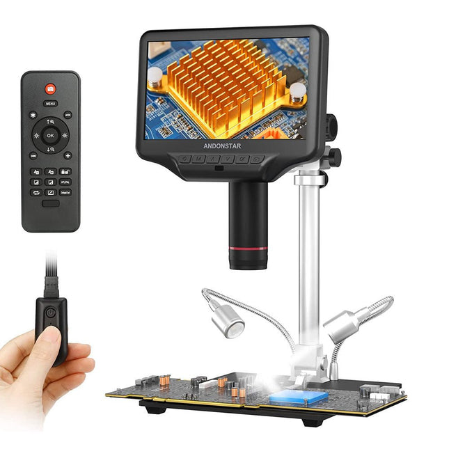
The Andonstar AD407 Pro microscope is suitable for various applications such as soldering SMDs or repair work. The microscope has a large adjustable 7" LCD display and comes with a remote. Compared to AD407, AD407 Pro offers an extra-high stand, which makes soldering of components even easier.
Specifications
Screen size
7 inch (17.8 cm)
Image sensor
4 MP
Video output
UHD 2880x2160 (24fps)FHD 1920x1080 (60fps/30fps)HD 1280x720 (120fps)
Video format
MP4
Magnification
Up to 270 times (27 inch HDMI monitor)
Photo resolution
Max. 12 MP (4032x3024)
Photo format
JPG
Focus range
Min. 5 cm
Frame Rate
Max. 120fps
Video interface
HDMI
Storage
microSD card (up to 64 GB)
Power source
5 V DC
Light source
2 LEDs with the stand
Stand size
20 x 18 x 32 cm
Included
1x Andonstar AD407 Pro Digital Microscope
1x Metal stand with 2 LEDs
1x UV filter (already assembled in the lens)
1x IR remote
1x Switch cable
1x Power adapter
1x Wrench
2x Metal clips
1x HDMI cable
1x Manual
Downloads
Manual
Model Comparison
AD407
AD407 Pro
AD409
AD409 Pro-ES
Screen size
7 inch (17.8 cm)
7 inch (17.8 cm)
10.1 inch (25.7 cm)
10.1 inch (25.7 cm)
Image sensor
4 MP
4 MP
4 MP
4 MP
Video output
2160p
2160p
2160p
2160p
Interfaces
HDMI
HDMI
USB, HDMI, WiFi
USB, HDMI, WiFi
Video format
MP4
MP4
MP4
MP4
Magnification
Up to 270x
Up to 270x
Up to 300x
Up to 300x
Photo resolution
Max. 4032x3024
Max. 4032x3024
Max. 4032x3024
Max. 4032x3024
Photo format
JPG
JPG
JPG
JPG
Focus distance
Min. 5 cm
Min. 5 cm
Min. 5 cm
Min. 5 cm
Frame rate
Max. 120f/s
Max. 120f/s
Max. 120f/s
Max. 120f/s
Storage
microSD card
microSD card
microSD card
microSD card
PC support
No
No
Windows
Windows
Mobile connection
No
No
WiFi + Measurement
WiFi + Measurement
Power source
5 V DC
5 V DC
5 V DC
5 V DC
Light source
2 LEDs with the stand
2 LEDs with the stand
2 LEDs with the stand
2 LEDs with the stand
Endoscope
No
No
No
Yes
Stand size
20 x 12 x 19 cm
20 x 18 x 32 cm
18 x 20 x 30 cm
18 x 20 x 32 cm
Weight
1.6 kg
2.1 kg
2.2 kg
2.5 kg
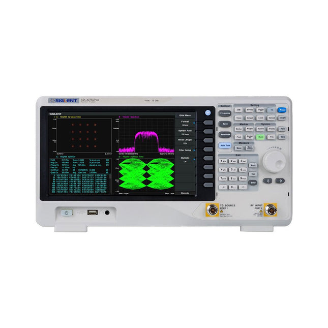
The Siglent SSA3075X Plus spectrum analyzer is a powerful and flexible tool for RF signal and network analysis. With a frequency range of 7.5 GHz, the analyzer delivers reliable automatic measurements and multiple modes of operation: spectrum analyzer the base, optional functions include RF power measurement, vector signal modulation analysis, reflection measurement, and EMI test.
Applications include broadcast monitoring/evaluation, site surveying, S-parameter measurement, analog/digital modulation analysis, EMI pre-compliance test, research and development, education, production, and maintenance.
Features
Spectrum Analyzer Frequency Range from 9 kHz to 7.5 GHz
–165 dBm/Hz Displayed Average Noise Level (Typ.)
–98 dBc/Hz. @ 10 kHz Offset Phase Noise (1 GHz, Typ.)
Level Measurement Uncertainty <0.7 dB (Typ.)
1 Hz Minimum Resolution Bandwidth (RBW)
Preamplifier (Std.)
Tracking Generator (incl. free of charge)
Analog and Digital Signal Modulation Analysis Mode (opt.)
Reflection Measurement Kit (opt.)
EMI Filter and Quasi-Peak Detector Kit (opt.)
Advanced Measurement Kit (opt.)
10.1-inch Multi-Touch Screen , Mouse and Keyboard supported
Web Browser Remote Control on PC and Mobile Terminals and File Operation
Specifications
SSA3015X Plus
SSA3021X Plus
SSA3032X Plus
SSA3075X Plus
Frequency Range
9 kHz ~ 1.5 GHz
9 kHz ~ 2.1 GHz
9 kHz ~ 3.2 GHz
9 kHz ~ 7.5 GHz
Resolution Bandwidth
1 Hz ~ 1 MHz
1 Hz ~ 1 MHz
1 Hz ~ 1 MHz
1 Hz ~ 3 MHz
Phase Noise
<–99 dBc/Hz
<–98 dBc/Hz
<–98 dBc/Hz
<–98 dBc/Hz
Total Amplitude Accuracy
<1.2 dB
<0.7 dB
<0.7 dB
<0.7 dB
Display Average Noise Level
–156 dBm/Hz
–161 dBm/Hz
–161 dBm/Hz
–165 dBm/Hz
Included
Siglent SSA3075X Plus spectrum analyzer
USB cable
Power cord
Quick start guide
Downloads
Datasheet
Manual
Documentation
Firmware
Buch: Logic Analyzer im Einsatz
Schritt-für-Schritt-Anleitungen führen Sie in die Analyse moderner Protokolle von I²C, SPI, UART, RS-232, NeoPixel, WS28xx, HD44780 und 1-Wire ein. Anhand von zahlreichen Experimentierschaltungen mit dem Raspberry Pi Pico, Arduino Uno und dem Bus Pirate üben Sie die praxisnahe Anwendung gängiger USB-Logikanalysatoren ein.
Alle in diesem Buch vorgestellten Experimentierschaltungen wurden vollständig getestet und sind funktionsfähig. Die notwendigen Programmlistings sind enthalten, es sind keine besonderen Programmier- oder Elektronikkenntnisse für diese Schaltungen notwendig. Es werden die Programmiersprachen MicroPython und C mit den Entwicklungsumgebungen Thonny und Arduino IDE eingesetzt.
Dieses Buch verwendet mehrere Modelle flexibler und weit verbreiteter USB-Logikanalysatoren und zeigt die Stärken und Schwächen jeder Preisklasse. Sie werden kennenlernen, welche Kriterien für Ihre Arbeit wichtig sind und in der Lage sein, das für Sie passende Gerät zu finden.
Egal ob Arduino, Raspberry Pi oder Raspberry Pi Pico: Die abgebildeten Beispielschaltungen ermöglichen einen schnellen Start in die Protokollanalyse und können auch als Grundlage für eigene weitere Experimente dienen.
Sie werden alle wichtigen Begriffe und Zusammenhänge kennenlernen, eigene Experimente durchführen, selbstständig Protokolle analysieren und nach der Lektüre dieses Buches – im Bereich der digitalen Signale und Protokolle – ein umfassendes Wissen aufgebaut haben.
USB Logic Analyzer (8 Kanäle, 24 MHz)
Dieser USB Logic Analyzer ist ein 8-Kanal-Logikanalysator, bei dem jeder Eingang doppelt für die analoge Datenaufzeichnung dient. Es eignet sich perfekt zum Debuggen und Analysieren von Signalen wie I²C, UART, SPI, CAN und 1-Wire. Dabei wird ein digitaler Eingang, der mit einem zu testenden Gerät (DUT) verbunden ist, mit einer hohen Abtastrate abgetastet. Die Verbindung zum PC erfolgt via USB.
Technische Daten
Kanäle
8 digitale Kanäle
Maximale Abtastrate
24 MHz
Maximale Eingangsspannung
0 V ~ 5 V
Betriebstemperatur
0°C ~ 70°C
Eingangsimpedanz
1 MΩ || 10 pF
Unterstützte Protokolle
I²C, SPI, UART, CAN, 1-Wire etc.
PC-Verbindung
USB
Abmessungen
55 x 28 x 14 mm
Downloads
Software
Dieses Bundle enthält:
Buch: Logic Analyzer im Einsatz (Einzelpreis: 40 €)
USB Logic Analyzer (8 Kanäle, 24 MHz) (Einzelpreis: 20 €)
USB-Kabel
Jumper Wire Ribbon Kabel
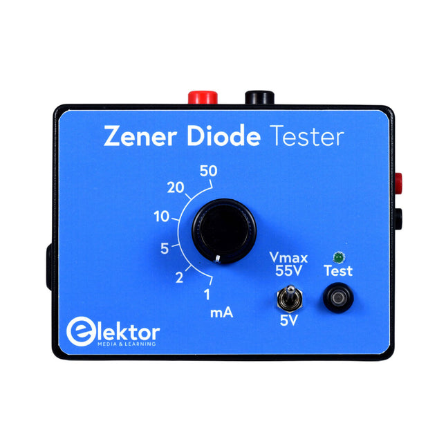
The Elektor Zener Diode Tester is essentially a constant-current source that can be switched in steps from 1 to 50 mA. It can be used to test Z-diodes up to a maximum of 54 V. Thanks to a 60-V step-up converter, the device can be powered by the usual 5 to 12 V.
The principle of this tester is straightforward. A Z-diode or other DUT (device under test, such as an LED) is biased by an adjustable current source. The voltage across the DUT can be measured with a multimeter. The voltage of most (small) Z-diodes is specified at a current of 5 mA. Depending on the application, the voltage at other currents can also be of interest. That is why six current settings are available: 1, 2, 5, 10, 20, and 50 mA. LEDs are often specified at a current of 20 mA.
What can be tested is:
Whether a Z-diode is defective (short circuit or high impedance).
Whether a Z-diode exhibits the correct Z-voltage.
How a Z-voltage changes with different currents.
What exact voltage is present at an integrated voltage reference.
Whether LEDs in a series chain differ in brightness (hence the 20 mA current).
What the current gain is for different base currents in (power) transistors.
The kit contains all parts listed in the bill of materials including PCB and enclosure.
Specifications
Supply voltage
5…12 V/2 A (USB-C)
Supply current (Itest = 50 mA)
1.1 A @ 5 V / 412 mA @ 12 V
Selectable currents
1, 2, 5, 10, 20, and 50 mA
Max. test voltage
>54 V @ Itest ≥1 mA
Max. output voltage
60 V @ Itest = 0 mA
Voltage limit at 5 V
4.5 V @ Itest = 1 mA / 5.18 V @ Itest = 50 mA
Enclosure dimensions
110 x 82 x 44 mm
PCB size
105.4 x 67.3 mm
Connections
4 mm banana sockets for multimeter
2 mm banana sockets for test clips
USB-C socket for power supply
Included
Resistors
R1 = 3.3 kΩ, 600 mW, 1%
R2 = 0.15 Ω, 1 W, 5%, LS 12.7 mm, ø 3.5 mm
R3, R8 = 180 Ω, 600 mW, 1%
R4, R6, R16 = 1 kΩ, 600 mW, 1%
R5, R19 = 47 kΩ, 600 mW, 1%
R7 = 3.9 kΩ, 1 W, 5%, LS 12.7 mm, ø 3.5 mm
R9, R10, R12 = 10 kΩ, 600 mW, 1%
R11, R13 = 100 Ω, 600 mW 1%
R14 = 249 Ω, 600 mW, 1%
R15 = 499 Ω, 600 mW, 1%
R17 = 2.49 kΩ, 250 mW, 1%
R18 = 4.99 kΩ, 250 mW, 1%
Capacitors
C1 = 470 uF / 35 V, 20%, Ir = 1.86 A, ø 12.5 mm, LS 5 mm, ESR = 0.038 Ω (Panasonic EEUTP1V471)
C2 = 1 uF / 100 V, 10%, X7R, LS 5 mm
C3 = 2.2 nF / 50 V, 10%, X7R, LS 5 mm
C4, C7 = 100 nF / 100 V, 10%, X7R, LS 5 mm
C5 = 100 uF / 100 V, 20%, ø 14 mm max., LS 5 mm
C6 = 1 nF / 100 V, 10%, X7R, LS 5 mm
Inductor
L1 = 100 uH, Irms = 2.4 A, Isat = 3.5 A, 0.09 Ω, radial, pitch 2.5/5/10 mm, ø 14 mm max. (Kemet SBC8-101-242)
Semiconductors
D1 = MUR120G, DO-41
D2, D4 = STPS3150RL, DO-201AD
D3 = Z-diode, 18 V, 1.3 W (BZX85C18)
D5 = Z-diode, 5.1 V, 0.5 W (1N5231B)
LED1 = LED in pushbutton S1
LED2 = LED, green, 3 mm
IC1 = MC34063, DIP-8
IC2 = LM4040BIZ-5.0/NOPB, TO-92 (TO-226AA-3)
IC3 = TL051CP, DIP-8
T1 = BC327.25, TO-92
T2 = STP40NF10L, TO-220
T3 = IRF9510PBF, TO-220
T4 = 2N7000, TO-92
Others
K1, K2, S1, S3 = 2-way screw terminal block, LS 3.5 mm, max. 1.5 mm²
connected to K1 = USB-C socket, 30 V/3 A, chassis mounted, wired, 9 x 16 mm
connected to K2 = Banana Connector, 2 mm, Socket, 60 VDC, Panel Mount, red (Multicomp 24.102.1)
connected to K2 = Banana Connector, 2 mm, Socket, 60 VDC, Panel Mount, black (Multicomp 24.102.2)
Test clip, red, 30 VAC/60 VDC (Hirschmann 931467101)
Test clip, black, 30 VAC/60 VDC (Hirschmann 931467100)
S1 = Pushbutton, panel mount, SPST-NO, 30 DC/100 mA, with red LED
S2 = Rotary Switch, 6 position, 2 pole, 30°, 250 V/150 mA
S3 = Toggle switch, panel mount, SPDT, solder lugs, 28 VDC
T2, T3 = Heat sink, 15°C/W, FK 214 SA-CB
Enclosure Hammond 1591XXSSBK, ABS, 110 x 82 x 44 mm
Knob for S2, round shaft 6 mm, ø 21 mm, with indicator line (Multicomp CP-LB21-6-6D)
4 x Self-tapping screw #4-1/4", carbon steel, pan head
Banana plug, red, 2 mm, 60 VDC (Multicomp 25.205.1)
Banana plug, black, 2 mm, 60 VDC (Multicomp 25.205.2)
Banana socket, black 4 mm, panel mount
Banana socket, red 4 mm, panel mount
for LED1, LED2 = Pin header, 1 x 2, vertical, pitch 2.54 mm
for LED1, LED2 = Pin socket, 1 x 2, vertical, pitch 2.54 mm
for T2, T3 = M3 screw, 10 mm, steel, pan head
2 x M3 washer, plain, steel
4 x M3 nut
for IC1, IC3 = DIP-8 socket
Wire, black, 0.25 mm² (24 AWG), stranded 14 x 0.15 mm, 1 m
Wire, red, 0.25 mm² (24 AWG), stranded 14 x 0.15 mm, 1 m
PCB 250772-1 v1.1
Links
Article
Elektor Labs
DEAL: Order the HackRF Pro now and get the new e-book "SDR with HackRF One & HackRF Pro" worth €20 for FREE!
HackRF Pro is latest Software Defined Radio (SDR) from Great Scott Gadgets and the powerful successor to the legendary HackRF One. With a frequency range from 100 kHz to 6 GHz, it covers an enormous spectrum for transmitting and receiving radio signals.
Designed as an open-source hardware platform, the HackRF Pro is the ideal tool for analyzing and developing modern wireless technologies. It can be used flexibly as a USB peripheral or programmed for standalone operation.
Specifications
Frequency: 100 kHz to 6 GHz
Adjustable from 0 Hz to 7.1 GHz
Half-duplex transceiver
Up to 20 million samples per second
8-bit quadrature samples (8-bit I and 8-bit Q)
Compatible with GNU Radio, SDR#, and more
Software-configurable RX and TX gain and baseband filter
Software-controlled RF port power (50 mA at 3.3 V)
SMA RF connector
SMA clock input and output for synchronization and triggering
Convenient buttons for programming
Internal pin headers for expansion
High-Speed USB 2.0 with USB-C connector
USB-powered
Open source hardware
Compared to its predecessor, HackRF Pro offers a variety of new features, including:
Wider operating frequency range
Improved RF performance with flatter frequency response
USB-C connector
Built-in TCXO crystal oscillator for superior timing stability
Logic upgrade from a CPLD to a power-efficient FPGA
Elimination of the DC spike
Extended-precision mode with 16-bit samples for low sample rates (typical ENOB: 9-11)
Half-precision mode with 4-bit samples at up to 40 Msps
More RAM and flash memory for custom firmware
Installed shielding around the radio section
Trigger input and output accessible through clock connectors
Cutout in the PCB provides space for future add-ons
Improved power management
Enhanced RF port protection
Facility to hardware-disable transmit mode
Full Compatibility: Thanks to its proven architecture, existing software for the HackRF One can also be used directly with the HackRF Pro. The HackRF Pro offers seamless backward compatibility while significantly increasing performance.
Note: An antenna is not included. We recommend the ANT500 for the best experience.
Included
HackRF Pro SDR with plastic enclosure
NEW e-book: SDR with HackRF One & HackRF Pro (normal price: €20)
Downloads
Documentation
GitHub
The OWON SDS1102 is an affordable benchtop digital oscilloscope that combines solid performance with essential measurement features. This 2-channel oscilloscope offers a 100 MHz bandwidth, a 1 GS/s sampling rate, a 7-inch LCD display, and a 10 kpts memory depth, making it a practical choice for everyday electronics testing, troubleshooting, and education.
The SDS1102 features a simplified trigger system with level and edge triggering, making it easy to capture and analyze common signals. It is designed for applications that do not require deep memory or advanced trigger functions, offering a straightforward and cost-effective solution for basic signal analysis.
Features
Bandwidth: 100 MHz
2 channels
Sample rate: 1 GS/s
Ultra-thin body
7-inch high-res LCD
SCPI and LabVIEW supported
Specifications
Bandwidth
100 MHz
Horizontal Scale (s/div)
5 ns/div – 1000 s/div
Channel
2
Vertical Sensitivity
5 mV/div – 5 V/div (at input)
DC Gain Accuracy
3%
Vertical Resolution (A/D)
8 bits (2 channels simultaneously)
Input
Input Impedance
1 MΩ, 10 pF
Input Coupling
AC, DC, GND
Max Input Voltage
±400 V, CATI, CATII
Passive probes
х1; х10
Probe Attenuation Factor
х1; х10; х100; х1000
Trigger System
Trigger Mode
Auto, Normal, Single
Trigger Type
Edge, Video
Edge Trigger Source
CH1, CH2
Video Trigger
Sampling Type
Real-time
Sample Rate
1 GS/s
Equivalent Sample Rate
No
Wavelength
10K pts
Interpolation
sin(x)/x
Measurement and Mathematical Treatment System
Automatic Measurement
Vpp, Vavg, RMS, Frequency, Period, Vmax, Vmin, Vtop, Vbase, Width, Overshoot, Pre-shootRise time, Fall time, +Width, -Width, +Duty, -Duty, Delay A→B, Delay A→B, area, cycle area
Math Functions
Addition, Subtraction, Multiplication, Division, FFT
General Characteristics
Display type
7" color LCD
Display Resolution
800 x 480
Power
100-240 V, 45-440 Hz, <15 W
Dimensions
301 x 70 x 152 mm
Weight
1.1 kg
Included
1x OWON SDS1102 Oscilloscope
2x Oscilloscope probes
1x Probe adjust
1x Mains power cord
1x USB cable
1x CD-Rom
1x Quick guide
Downloads
Quick Guide
Manual
PC Software
SCPI Commands
This bundle contains the AI Fusion Lab Kit – which includes over 450 components – and the book Physical AI with Raspberry Pi, offering a comprehensive, hands-on introduction to AI, electronics, and Python programming.
Build practical projects that combine computer vision, voice interaction, sensors, motors, and large language models. The included book guides you step by step from Raspberry Pi setup and hardware control to advanced applications using OpenCV, MediaPipe, YOLO, OpenAI services, and local Ollama models.
SunFounder AI Fusion Lab Kit for Raspberry Pi (450+ parts)
The AI Fusion Lab Kit transforms a Raspberry Pi into a complete platform for learning artificial intelligence, electronics, and Python programming. It supports Raspberry Pi 5, 4B, 3B+, 3B, and Zero 2 W, as well as popular AI models and services including ChatGPT, Gemini, Grok, DeepSeek, Qwen, Doubao, and Ollama.
With its camera, Pan-Tilt HAT, 10-axis sensor module, microphone, speaker, and electronic components, the kit enables users to build interactive AI projects that combine voice, vision, movement, and sensor data. It is suitable for beginners, students, makers, and anyone who wants to explore practical AI applications.
Build Multimodal AI Projects
Combine large language models with speech recognition, text-to-speech, camera vision, sensors, and breadboard circuits. Create projects that can listen, speak, see, react, and interact with their environment while learning how modern AI systems work.
Explore AI Vision and Object Tracking
Use YOLO, OpenCV, and MediaPipe to detect and track objects, colors, faces, and human movement. The motorized Pan-Tilt HAT allows the camera to follow targets automatically, demonstrating how computer vision and motion control work together.
Voice AI with the Fusion HAT+
The Fusion HAT+ simplifies hardware control through a unified Python library and supports safe Raspberry Pi shutdown. Its integrated microphone and speaker make it easy to develop voice-controlled assistants and other conversational AI applications.
Compatible with Raspberry Pi 5, 4B, 3B+, 3B, and Zero 2 W
Supports multiple cloud-based and local AI models
Includes camera, Pan-Tilt HAT, 10DOF module, microphone, and speaker
Projects covering voice AI, computer vision, sensors, and electronics
Video lessons, documentation, and sample code
Book: Physical AI with Raspberry Pi
Using the Raspberry Pi and the AI Fusion Lab Kit, this book takes you step by step from the fundamentals of hardware interfacing to the development of intelligent systems capable of seeing, listening, speaking, and making decisions. Whether you are a student, educator, maker, or professional engineer, you will gain valuable experience through projects designed to build both knowledge and confidence.
Beginning with system setup, GPIO programming, sensors, displays, motors, and automation techniques, the book gradually introduces more advanced topics, including speech recognition, text-to-speech synthesis, conversational AI, object recognition, and machine learning. Along the way, you will learn how to create voice-controlled devices, intelligent assistants, camera tracking systems, environmental monitoring solutions, and AI-powered embedded applications.
Explore modern technologies such as OpenAI services, Ollama local large language models, OpenCV, MediaPipe, and YOLO object detection while gaining practical experience with real-world applications used in robotics, industrial automation, smart devices, and autonomous systems. You’ll discover how intelligent software can interact with sensors, cameras, motors, and displays to create systems that respond naturally to the world around them.
Rather than simply following code examples, you will be encouraged to experiment, customize, and expand every project. The techniques and skills developed throughout this book provide a solid foundation for future innovation, rapid prototyping, research, and product development. If you are ready to move beyond traditional electronics and explore the future of intelligent embedded systems, this book will guide you every step of the way.
This bundle contains:
SunFounder AI Fusion Lab Kit for Raspberry Pi (normal price: €100)
Book: Physical AI with Raspberry Pi (normal price: €45)
Not included
Raspberry Pi
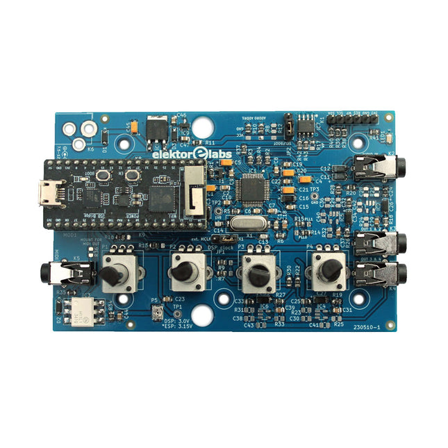
The Elektor Audio DSP FX Processor combines an ESP32 microcontroller and an ADAU1701 Audio DSP from Analog Devices. Besides a user-programmable DSP core, the ADAU1701 has high-quality analog-to-digital and digital-to-analog converters built-in and features an I²S port. This makes it suitable as a high-quality audio interface for the ESP32.
Programs for the ESP32 can be created with Arduino, Platform IO, CMake or by using the Espressif IDF in another way. Programs for the ADAU7101 audio DSPs are created with the free visual programming tool SigmaStudio by dragging and dropping pre-defined algorithm blocks on a canvas.
Applications
Bluetooth/Wi-Fi audio sink (e.g. loudspeaker) & source
Guitar effect pedal (stomp box)
Music synthesizer
Sound/function generator
Programmable cross-over filter for loudspeakers
Advanced audio effects processor (reverb, chorus, pitch shifting, etc.)
Internet-connected audio device
DSP experimentation platform
Wireless MIDI
MIDI to CV converter
and many more...
Specifications
ADAU1701 28-/56-bit, 50-MIPS digital audio processor supporting sampling rates of up to 192 kHz
ESP32 32-bit dual-core microcontroller with Wi-Fi 802.11b/g/n and Bluetooth 4.2 BR/EDR and BLE
2x 24-bit audio inputs (2 V RMS, 20 kΩ)
4x 24-bit audio outputs (0.9 V RMS, 600 Ω)
4x Control potentiometer
MIDI in- and output
I²C expansion port
Multi-mode operation
Power supply: 5 V DC USB or 7.5-12 V DC (barrel jack, center pin is GND)
Current consumption (average): 200 mA
Included
1x ESP32 Audio DSP FX Processor board (assembled)
1x ESP32-PICO-KIT
2x Jumpers
2x 18-pin headers (female)
4x 10 KB potentiometers
Downloads
Documentation
GitHub
This bundle includes the Red Pitaya STEMlab 125-14 PRO Gen 2 Starter Kit and the new book "Experimenting with Red Pitaya STEMlab Gen 2".
The Red Pitaya STEMlab 125-14 PRO Gen 2 Starter Kit is a powerful and flexible platform for signal processing, data acquisition, and electronic measurement applications. Designed for engineers, developers, researchers, and educators, this kit provides everything required to start building advanced measurement and control systems.
At the core of the kit is the STEMlab 125-14 PRO Gen 2 board, an upgraded and ultra-lightweight development platform. Powered by the Xilinx Zynq-7010 SoC with 512 MB of RAM, it combines FPGA programmability with ARM processing power to enable high-performance instrumentation and custom signal-processing solutions.
The board offers 14-bit ADC and DAC resolution, a 125 MS/s sampling rate, an input range of ±20 V, and up to 60 MHz bandwidth. Its improved low-noise analog front-end, USB-C connectivity, and compact design make it suitable for demanding applications such as RF development, radar systems, photonics research, software-defined radio (SDR), and industrial automation.
The Starter Kit includes all essential accessories for immediate use: a microSD card with preinstalled operating system, power supply, Ethernet cable for remote access, two 100 MHz oscilloscope probes, and SMA-to-BNC adapters for flexible signal connections.
The Red Pitaya STEMlab 125-14 PRO Gen 2 Starter Kit is an excellent platform for rapid prototyping, FPGA development, measurement instrumentation, and advanced electronics experimentation.
Features
14-bit ADC and DAC resolution
125 MS/s sampling rate
±20 V input range
Up to 60 MHz bandwidth
Xilinx Zynq-7010 SoC (FPGA + ARM processor)
512 MB RAM
Low-noise analog front- and back-ends
Applications
RF development and testing
Radar and wireless systems
Software-defined radio (SDR)
Photonics and optical research
Industrial automation and control systems
Signal analysis and instrumentation
Rapid prototyping of electronic measurement systems
Specifications
Processor
Dual-core ARM Cortex-A9
FPGA
AMD Xilinx Zynq-7010 SoC
RAM
512 MB (4 Gb)
Storage
microSD card (up to 32 GB)
Operating System
Linux-based Red Pitaya OS
ADC Resolution
14-bit
DAC Resolution
14-bit
Bandwidth
60 MHz (DC)
Sampling Rate
125 MS/s
Analog Input Channels
2
Analog Output Channels
2
Input Voltage Range
±1 V (LV) / ±20 V (HV)
Input Impedance
1 MΩ / 10 pF
Output Voltage Range
±1 V
Ethernet
1x Gigabit Ethernet (RJ45)
USB
2x USB-C 2.0 (for power and console)
Digital I/O
16x GPIO (3.3 V)
Communication Interfaces
I²C, SPI, UART, CAN
Power Supply
5 V/3 A via USB-C
Dimensions
106.8 x 60.0 x 17.9 mm
Included
1x Red Pitaya STEMlab 125-14 PRO Gen 2 board
2x 100 MHz oscilloscope probes
2x SMA-to-BNC adapters
1x microSD card with preinstalled OS
1x USB-C Power supply
1x Ethernet cable
Downloads
Documentation
Schematics
Book: Experimenting with Red Pitaya STEMlab Gen 2
With this new book, Red Pitaya goes beyond a versatile board. It becomes a powerful laboratory instrument for precision measurement, analysis, and control.
From the fundamentals of electronic project development, monitoring, control, and design to testing, this book walks you step-by-step through everything you need to know to harness the full potential of Red Pitaya hardware and software.
The book presents real-time, FPGA-based projects that are developed on a PC using the Vivado environment, then transferred to the Red Pitaya for execution and testing.
You will learn about enhanced performance, expanded I/O capabilities, improved FPGA features, and advanced connectivity options that open up new frontiers for precision measurement, monitoring, and control in your embedded applications.
Inside the book you will discover:
A deep dive into Red Pitaya architecture and hardware design
Electronic experiments using Red Pitaya for measurement and monitoring
Hands-on projects using the Python programming language
Practical guidance for FPGA programming using Red Pitaya
Red Pitaya FPGA projects using the Verilog HDL under Vivado IDE
Practical design of electronic projects including measurement and testing
Step-by-step examples that bridge theory and real-world implementation
Whether you are designing your own electronic circuits, developing signal analysis tools, or creating real-time control or monitoring systems, this book provides you the knowledge and confidence you need to fully learn and customize the Red Pitaya platform.
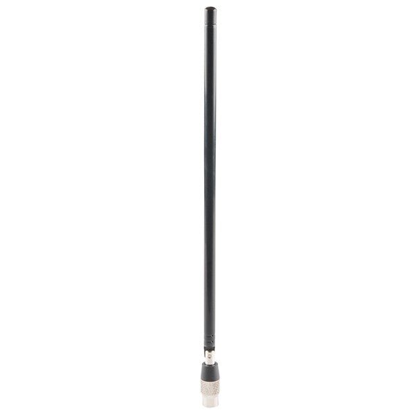
ANT500 from Great Scott Gadgets is a telescopic antenna designed for operation from 75 MHz to 1 GHz. Its total length is configurable from 20 cm to 88 cm. ANT500 is constructed of stainless steel and features an SMA male connector, rotating shaft, and adjustable elbow.
ANT500 is a 50 ohm general purpose antenna. It is the perfect first antenna for use with HackRF One/Pro.